SlideShare a Scribd company logo
1 of 60
Download to read offline
Copyright 2010 Carrier Corporation Form 30RAP-3PD
The AquaSnap chiller is an effective all-
in-one package that is easy to install
and easy to own. AquaSnap chillers
operate quietly and efficiently. Value-
added features include:
• Rotary scroll compression
• HFC Puron® refrigerant (R-410A)
• Low-sound AeroAcoustic™ fan
system
• Easy to use ComfortLink™ controls
• Optional integrated hydronic pump
package with VFD (variable frequency
drive) compatible motors
• Microchannel condenser coil
technology
• Accessory fluid storage tank
• Optional digital scroll compressors
Features/Benefits
Carrier’s superior chiller
design provides savings at
initial purchase, at installa-
tion, and for years afterward.
Costs less right from the start
Carrier’s AquaSnap chillers feature a
compact, all-in-one package design
that installs quickly and easily on the
ground or the rooftop. The optional
pump and hydronic components are
already built in; this costs less than buy-
ing and installing the components indi-
vidually. The chiller’s fully integrated
and pre-assembled hydronic system in-
stalls in minutes. No other chiller in
this class installs so easily and inexpen-
sively. The preassembled and integrat-
ed hydronic module utilizes top-quality
components and pumps to ensure
years of reliable operation. Use of the
optional fluid storage tank reduces in-
stallation costs and ensures sufficient
fluid volume is available for close-
coupled and process cooling applica-
tions. The AquaSnap unit’s high effi-
ciency keeps costs down.
AQUASNAP®
30RAP010-060
Air-Cooled Chillers
with PURON® Refrigerant (R-410A)
10 to 60 Nominal Tons
(35 to 210 Nominal kW)
Product
Data
a30-4827
a30-4826
2
AquaSnap® chillers make
noise in the marketplace, not
the workplace.
The AquaSnap chiller’s low-sound
AeroAcoustic™ fan produces up to half
the sound level of propeller fans. Much
of the noise reduction is in frequencies
where noise is most annoying, which
makes AquaSnap chillers ideal for
sound-sensitive environments. When
lower ambient temperatures allow
part-load operation or during sched-
uled nighttime operation, the units op-
erate with fewer fans and become even
quieter. AquaSnap chillers are quiet
during the day and even quieter at
night.
The savings will continue to
mount
Besides costing less to buy and install,
AquaSnap chillers are also more af-
fordable to operate. Carrier’s Aqua
Series chillers are our most efficient
air-cooled models. The AquaSnap
chiller provides full-load EER (Energy
Efficiency Ratio) up to 10.5 and IPLV
(integrated part-load value) up to 15.3.
AquaSnap chillers use ultra-quiet, high-
efficiency rotary scroll compressors,
operated in single (sizes 010 and 015)
and tandem (sizes 018 to 060) per in-
dependent circuit for greater efficiency
at partial loads.
Electronic expansion valve (EXV)
allows for precise control through all
operating ranges, resulting in higher
efficiency and improved reliability.
Proven reliability that’s built in
Thousands of AquaSnap chillers are
already in service around the world.
This field-proven design is backed by a
12-month warranty that includes the
hydronic system. The compressors are
maintenance-free and protected by an
auto-adaptive control that minimizes
compressor wear. Unit sizes 035 and
up have two independent refrigerant
circuits. Year-round operation is
standard, from –20 F (–29 C) (with
optional cooler heater, low ambient
control, and wind baffles) to 120 F
(50 C).
Rotary scroll compressors provide
smooth, quiet and reliable operation.
All-in-one package
AquaSnap chillers provide the most
comprehensive chilled water circuit
available for any air-cooled chiller.
Included is a brazed plate direct
expansion cooler that may be remote-
mounted. The cooler is also completely
drainable with factory-installed vents
and drains.
Electronic thermal-dispersion
flow switch is included with the cool-
er. The switch is factory installed and
tested and contains no moving parts
for high reliability.
Optional integrated hydronics
package is more than just a pump, it
is an entire chilled water system,
including:
• Single/dual pumps up to 7.5 hp
and 120 ft head
• Regular strainer
• Cleanout strainer
• Flow regulator
• Freeze protection to –20 F (–29 C)
(with freeze protection option)
• Heaters
• Required piping
• Pressure/temperature taps
• Isolation valves for dual pump
systems
• VFD compatibility
The factory-installed and tested hy-
dronics package provides faster, sim-
pler and less expensive installation.
Digital scroll compressors are
available as a factory-installed option.
These allow for incremental unloading
with capacity modulation to better
match building load when compared to
standard scroll compressors.
Environmentally sound
Carrier’s Puron® refrigerant (R-410A)
enables you to make a responsible de-
cision in the protection of the earth’s
ozone layer. Puron refrigerant is an
HFC refrigerant that does not contain
chlorine that is damaging to the ozone
layer. Puron refrigerant is unaffected
by the Montreal Protocol. Puron refrig-
erant is a safe, non-toxic*, efficient and
environmentally sound refrigerant for
the future.
Durable construction
The 30RAP chillers have a structurally
sound base that can be point-loaded,
therefore, no perimeter base rail is re-
quired. All 30RAP units have weather-
ized cabinets constructed of heavy-duty
galvanized steel with exterior panels
painted with corrosion-resistant baked
enamel. Inside and outside surfaces are
protected to ensure long life and good
appearance. The durable, galvanized
steel, painted components exceed the
requirements of the 500-hour salt
spray test per ASTM (American Soci-
ety for Testing and Materials) B117.
ComfortLinkTM controls speak
your language
The ComfortLink controls communi-
cate in plain English, making it as easy
as possible to monitor and control
each AquaSnap chiller while accurately
maintaining fluid temperatures. The
large scrolling marquee display acts as
a window into the unit’s operation,
providing easy-to-read information
about chiller performance and over
15 diagnostic functions. Carrier 30
Series chillers’ ComfortLink controls
provide features such as chilled water
temperature reset, demand limiting,
compressor wear minimization and
protection, temperature and pressure
displays and diagnostic functions.
These controls result in higher chiller
reliability, simplified training and more
productive service calls with corre-
spondingly lower operational and
maintenance costs.
Carrier’s exclusive accessory hand-
held Navigator™ display provides con-
venience and powerful information in
the palm of your hand. The Navigator
display helps technicians to quickly
diagnose problems and even prevent
them from occurring.
All AquaSnap units are ready to
be used with the Carrier Comfort
Network® (CCN) system.
AquaSnap units minimize the
impact on your footprint, as
well as your bottom line
The integrated hydronics and the
chilled fluid storage tank’s placement
under the chiller minimize the foot-
print, allowing easy installation almost
anywhere.
Novation® heat exchanger
technology
The Novation heat exchanger design
with microchannel (MCHX) condenser
coil is a robust, cost effective alterna-
tive to traditional coil design. These
coils are offered coated or uncoated to
match coil protection to site condi-
tions. The Carrier Electronic Catalog
(E-Cat) can be used to determine
whether or not corrosion protection is
recommended for particular applica-
tions in coastal/marine environments.
Features/Benefits (cont)
* Under ASHRAE Standard 34-1992, R-410A is
classified as an A1 refrigerant.
3
Following the input of the requested
data, the E-Cat program output will ad-
vise the appropriate coil to be used.
Other factors described in "Selection
Guide: Environmental Corrosion Pro-
tection, Novation Heat Exchanger with
Microchannel Coil Technology" catalog
number 04-581042-01 must also be
considered to determine if corrosion
protection is required.
Microchannel coils are more robust
than other coil types, making them
easier to clean without causing damage
to the coil.
Due to the compact all aluminum
design, microchannel coils will reduce
average unit operating weight by 25%
compared to the previous 30RA units.
The streamlined MCHX coil design
also reduces refrigerant charge by an
average of 60% compared to the pre-
vious 30RA units.
Run Status
Service Test
Temperature
Pressures
Setpoints
Inputs
Outputs
Configuration
Time Clock
Operating Modes
Alarms
Alarm Status
ENTER
MODE
ESCAPE
PROPELLER FANAEROACOUSTIC FAN
1/3 OCTAVE BAND CENTER FREQUENCY (Hz)
SOUNDPOWER[dB(A)]
AEROACOUSTIC™ FAN vs. PROPELLER FAN
PENETRATES BUILDING
STRUCTURE
25 40 63 130 168 250 400 630 1080 1600 2400 4000 6300 8000
90
85
80
75
70
65
60
55
50
Run Status
Service
Test
Tem
peratures
Pressures
Setpoints
Inputs
Outputs
Configuration
Time Clock
Operating
ModesAlarms
ENTER
ESC
MODE
Alarm Status
ComfortLink
SCROLLING MARQUEE DISPLAY
NAVIGATOR™ DISPLAY MODULE
OPTIONAL HYDRONIC PACKAGE
LOW-SOUND AEROACOUSTIC FAN
WITH NIGHTTIME LOW SOUND
AEROACOUSTIC FAN VS PROPELLER FAN
TUBES
FINS
MICROCHANNELS
MANIFOLD
NOVATION® HEAT EXCHANGER TECHNOLOGY
WITH MICROCHANNEL CONDENSER COILS
a30-4860
4
Table of contents
Page
Features/Benefits . . . . . . . . . . . . . . . . . . . . . . . . . . . . . . . . . . . . . . . . . . .1-3
Model Number Nomenclature . . . . . . . . . . . . . . . . . . . . . . . . . . . . . . . . . . . 4
AHRI Capacity Ratings . . . . . . . . . . . . . . . . . . . . . . . . . . . . . . . . . . . . . . . . 5
Physical Data . . . . . . . . . . . . . . . . . . . . . . . . . . . . . . . . . . . . . . . . . . . . . .6-8
Options and Accessories . . . . . . . . . . . . . . . . . . . . . . . . . . . . . . . . . . . . .9,10
Base Unit Dimensions . . . . . . . . . . . . . . . . . . . . . . . . . . . . . . . . . . . . .11-13
Accessory Dimensions . . . . . . . . . . . . . . . . . . . . . . . . . . . . . . . . . . . . .14-16
Selection Procedure . . . . . . . . . . . . . . . . . . . . . . . . . . . . . . . . . . . . . . . . . 17
Performance Data . . . . . . . . . . . . . . . . . . . . . . . . . . . . . . . . . . . . . . . .17-34
Typical Piping and Wiring . . . . . . . . . . . . . . . . . . . . . . . . . . . . . . . . . . .35-37
Electrical Data . . . . . . . . . . . . . . . . . . . . . . . . . . . . . . . . . . . . . . . . . . .38-45
Controls . . . . . . . . . . . . . . . . . . . . . . . . . . . . . . . . . . . . . . . . . . . . . . .46-48
Typical Control Wiring Schematic . . . . . . . . . . . . . . . . . . . . . . . . . . . . . . . 49
Application Data . . . . . . . . . . . . . . . . . . . . . . . . . . . . . . . . . . . . . . . . .50-55
Guide Specifications . . . . . . . . . . . . . . . . . . . . . . . . . . . . . . . . . . . . . . .56-60
Model number nomenclature
P 0 0 030RA 0 66 D –010
30RA – Air-Cooled AquaSnap Chiller
Refrigerant Type
P – Puron
Revision Level
– – Current Revision Level
Unit Sizes
010 025 045
015 030 050
018 035 055
020 040 060
Voltage
1 – 575-3-60
2 – 380-3-60
5 – 208/230-3-60
6 – 460-3-60
Condenser Coil/Low Sound Options
5 – MCHX, Value Sound Fan
6 – MCHX, E-coat, Value Sound Fan
D – MCHX, AeroAcoustic™ Fan
F – MCHX, E-coat, AeroAcoustic Fan
J – MCHX, AeroAcoustic Fan, Ultra-Low Sound
K – MCHX, E-coat, AeroAcoustic Fan, Ultra-Low Sound
Hydronic System
0 – No Pump
1 – Single Pump, 1 Hp
2 – Single Pump, 1.5 Hp
3 – Single Pump, 2 Hp
4 – Single Pump, 3 Hp
5 – Single Pump, 5 Hp
6 – Single Pump, 5 Hp High Head
7 – Single Pump, 7.5 Hp
8 – Dual Pump, 1 Hp
9 – Dual Pump, 1.5 Hp
B – Dual Pump, 2 Hp
C – Dual Pump, 3 Hp
D – Dual Pump, 5 Hp
F – Dual Pump, 5 Hp High Head
G – Dual Pump, 7.5 Hp
Ambient/Capacity Control/Interrupt Options
0 – Std Comp, Std Interrupt
1 – Hot Gas Bypass, Std Interrupt
2 – Digital Comp, Std Interrupt
3 – Std Comp, High SCCR
4 – Hot Gas Bypass, High SCCR
5 – Digital Comp, High SCCR
6 – Low Ambient, Std Comp, Std Interrupt
7 – Low Ambient, Hot Gas Bypass, Std Interrupt
8 – Low Ambient, Digital Comp, Std Interrupt
9 – Low Ambient, Std Comp, High SCCR
B – Low Ambient, Hot Gas Bypass, High SCCR
C – Low Ambient, Digital Comp, High SCCR
Electrical Options
0 – No Disconnect, No Cooler Heater
1 – No Disconnect, Cooler Heater
D – Non-Fused Disconnect, No Cooler Heater
F – Non-Fused Disconnect, Cooler Heater
Controls/Communications Options
0 – Std
5 – EMM
B – EMM, GFI
Packaging/Security Options
0 – Std Packaging
4 – Security Grilles/Hail Guards Only
8 – Skid Only
D – Skid, Security Grilles/Hail Guards
J – Skid, Top Crate, Bag
N – Skid, Top Crate, Bag, Security Grilles/Hail Guards®
AQUASNAP® CHILLER MODEL NUMBER DESIGNATION
LEGEND
EMM — Energy Management Module
GFI — Ground Fault Interrupting
MCHX — Microchannel Heat Exchanger
SCCR — Short Circuit Current Rating
Quality Assurance
Certified to ISO 9001: 2000
a30-5120
5
LEGEND * Air Conditioning, Heating, and Refrigeration Institute.
NOTE: Based on AHRI-550/590 standard rating conditions. Ratings are for
standard chillers only. Ratings do not include options.
UNIT
30RAP
CAPACITY COMPRESSOR
POWER INPUT
(kW)
FAN
POWER
(kW)
TOTAL
POWER
(kW)
FULL LOAD IPLV COOLER FLOW
RATE
COOLER
WATER
PRESSURE
DROP
Tons kW EER COP EER COP GPM L/s Ft wg kPa
010 10.5 36.8 10.7 1.2 12.0 10.5 3.1 14.5 4.2 25.1 1.6 13.7 40.9
015 14.0 49.2 15.6 1.3 16.8 10.0 2.9 13.1 3.8 33.6 2.1 15.7 46.8
018 16.1 56.6 15.6 3.0 18.6 10.4 3.0 14.3 4.2 38.6 2.4 15.6 46.5
020 18.8 66.1 19.1 2.9 21.9 10.3 3.0 14.0 4.1 45.2 2.9 14.2 42.4
025 23.4 82.3 24.5 2.8 27.4 10.3 3.0 15.0 4.4 56.3 3.6 17.8 53.1
030 27.6 97.1 30.9 2.7 33.6 9.9 2.9 14.7 4.3 66.3 4.2 20.9 62.3
035 34.4 121.0 35.9 3.8 39.7 10.4 3.0 15.2 4.5 82.5 5.2 13.2 39.4
040 38.9 136.8 42.3 3.8 46.1 10.1 3.0 15.2 4.5 93.4 5.9 13.8 41.2
045 43.1 151.6 48.6 3.4 52.0 10.0 2.9 15.3 4.5 103.4 6.5 15.3 45.6
050 47.3 166.3 53.1 3.8 57.0 10.0 2.9 14.5 4.2 113.5 7.2 19.1 57.0
055 51.8 182.2 56.4 5.3 61.7 10.1 3.0 14.5 4.2 124.2 7.8 17.6 52.5
060 56.0 196.9 60.8 5.3 66.2 10.2 3.0 14.3 4.2 134.4 8.5 20.5 61.2
COP— Coefficient of Performance
EER — Energy Efficiency Ratio
IPLV — Integrated Part Load Value
AHRI* capacity ratings
6
ENGLISH
LEGEND
*All units have Victaulic connections, sized for IPS Carbon Steel piping.
†Flow switch and strainer are standard on all units, with or without hydronic package.
UNIT 30RAP 010 015 018 020 025 030 035 040 045 050 055 060
OPERATING WEIGHT (lb)
MCHX Condenser Coil, No Pump 704 718 1125 1133 1242 1283 2163 2185 2238 2263 2369 2375
MCHX Condenser Coil, Single Pump 866 880 1288 1296 1405 1446 2507 2529 2582 2606 2713 2719
MCHX Condenser Coil, Dual Pump 1029 1043 1450 1458 1567 1608 2850 2872 2925 2950 3056 3062
REFRIGERANT TYPE R-410A, EXV Controlled System
Total Refrigerant Charge (lb) 8.6 9.6 14.6 15.2 16.7 17.6 29.2 29.9 33.5 33.7 34.3 34.5
Refrigerant Charge (lb) Ckt A/Ckt B 8.6/— 9.6/— 14.6/— 15.2/— 16.7/— 17.6/— 14.3/14.9 14.9/15.0 16.5/17.0 16.7/17.0 16.9/17.4 17.1/17.4
COMPRESSORS Scroll, Hermetic
Quantity 1 1 2 2 2 2 4 4 4 4 4 4
Speed (Rpm) 3500
(Qty, Tons) Ckt A (1) 11 (1) 15 (2) 9 (2) 10 (2) 13 (2) 15 (2) 10 (2) 10 (2) 11 (2) 13 (2) 13 (2) 15
(Qty, Tons) Ckt B — — — — — — (2) 9 (2) 11 (2) 13 (2) 13 (2) 15 (2) 15
Oil Charge (Pt) Ckt A/Ckt B 6.9/— 6.9/— 13.8/— 13.8/— 13.8/— 13.8/— 13.8/13.8 13.8/13.8 13.8/13.8 13.8/13.8 13.8/13.8 13.8/13.8
No. Capacity Steps
Standard 1 1 2 2 2 2 4 4 4 4 4 4
With Hot Gas Bypass — — 3 3 3 3 5 5 5 5 5 5
Digital Compressor Option 13 13 — 22 22 22 44 44 44 44 44 44
Minimum Capacity Step (%)
Standard 100 100 50 50 50 50 23 23 24 25 23 25
With Hot Gas Bypass — — 20 24 29 32 9 11 12 14 13 16
Digital Compressor Option 20 20 — 15 15 15 8 8 8 8 8 8
Capacity (%)
Circuit A 100 100 100 100 100 100 54 47 47 50 46 50
Circuit B — — — — — — 46 53 53 50 54 50
COOLER Brazed, Direct-Expansion Plate Heat Exchanger
Weight (lb) (empty) 22.4 27.5 31.8 40.3 46.3 80.6 99.4 117.9 125.3 137.5 160.4 160.4
Net Fluid Volume (gal) 0.6 0.8 0.9 1.2 1.4 2.0 2.6 3.3 3.5 4.1 5.0 5.0
Maximum Refrigerant Pressure (psig) 505 505 505 505 505 565 565 565 565 565 565 565
Maximum Water-Side Pressure
Without Pump(s) (psig)
300 300 300 300 300 300 300 300 300 300 300 300
Maximum Water-Side Pressure
With Pump(s) (psig)
150 150 150 150 150 150 150 150 150 150 150 150
CHILLER WATER CONNECTIONS (in.)
Inlet and Outlet, Victualic
(IPS Carbon Steel)*
2 2 2 2 2 2 21/2 21/2 21/2 21/2 21/2 21/2
Drain (NPT) 1/2
1/2
1/2
1/2
1/2
1/2
1/2
1/2
1/2
1/2
1/2
1/2
CONDENSER FANS
Standard Low-Sound AeroAcoustic™
Type
Plastic Type, Axial, Vertical Discharge
Fan Speed (Rpm) 850 850 850 850 850 850 850 850 850 850 850 850
No. Blades...Diameter (in.) 9...30 9...30 9...30 9...30 9...30 9...30 9...30 9...30 9...30 9...30 9...30 9...30
No. Fans 1 1 2 2 2 2 3 3 3 3 4 4
Total Airflow (Cfm) 9400 9400 17,500 17,500 19,400 19,400 29,600 29,500 29,300 30,500 38,800 38,800
Optional Value Sound Type Propeller Type, Axial, Vertical Discharge
Fan Speed (Rpm) 1140 1140 1140 1140 1140 1140 1140 1140 1140 1140 1140 1140
No. Blades...Diameter (in.) 4...30 4...30 4...30 4...30 4...30 4...30 4...30 4...30 4...30 4...30 4...30 4...30
No. Fans 1 1 2 2 2 2 3 3 3 3 4 4
Total Airflow (Cfm) 12,600 12,600 23,400 23,400 26,000 26,000 39,800 39,600 39,300 41,000 52,100 52,100
CONDENSER COILS Novation® MCHX Aluminum Tube, Aluminum Fin
Quantity (Ckt A/Ckt B) 1/— 1/— 1/— 1/— 1/— 1/— 1/1 1/1 1/1 1/1 1/1 1/1
Total Face Area (sq ft) 17 17 26 26 33 33 53 53 66 66 66 66
Maximum Refrigerant Pressure (psig) 656 656 656 656 656 656 656 656 656 656 656 656
HYDRONIC MODULE (Optional)† Pump(s), Strainer with Blowdown Valve, Expansion Tank, Pressure Taps, Drain and Vent Plugs, Flow Switch, and Balance Valve
Pump Single or Dual, Centrifugal Monocell Pump(s), 3500 Rpm. Dual pumps with check valves and isolation valves.
Expansion Tank Volume (gal)
Total/Acceptance 4.4/3.2 10.3/10.3
CHASSIS DIMENSIONS (ft - in.)
Length 5-7 5-7 7-5 7-5 7-5 7-5 7-5 7-5 7-5 7-5 7-5 7-5
Width 3-5 3-5 3-5 3-5 3-5 3-5 7-9 7-9 7-9 7-9 7-9 7-9
Height 5-6 5-6 5-6 5-6 6-6 6-6 5-6 5-6 6-6 6-6 6-6 6-6
EXV — Electronic Expansion Valve
MCHX — Microchannel Heat Exchanger
Physical data
7
SI
LEGEND
*All units have Victaulic connections, sized for IPS Carbon Steel piping.
†Flow switch and strainer are standard on all units, with or without hydronic package.
UNIT 30RAP 010 015 018 020 025 030 035 040 045 050 055 060
OPERATING WEIGHT (kg)
MCHX Condenser Coil, No Pump 319 326 510 514 564 582 981 991 1015 1026 1075 1077
MCHX Condenser Coil, Single Pump 393 399 584 588 637 656 1137 1147 1171 1182 1231 1233
MCHX Condenser Coil, Dual Pump 467 473 658 661 711 729 1293 1303 1327 1338 1386 1389
REFRIGERANT TYPE R-410A, EXV Controlled System
Total Refrigerant Charge (kg) 3.9 4.4 6.6 7.1 7.6 8.0 13.4 13.6 15.6 15.7 16.0 16.1
Refrigerant Charge (kg) Ckt A/Ckt B 3.9/— 4.4/— 6.6/— 7.1/— 7.6/— 8.0/— 6.8/6.7 6.8/6.8 7.8/7.8 7.8/7.8 7.9/8.1 8.1/8.1
COMPRESSORS Scroll, Hermetic
Quantity 1 1 2 2 2 2 4 4 4 4 4 4
Speed (R/s) 58.3
(Qty, kW) Ckt A (1) 38 (1) 53 (2) 32 (2) 35 (2) 46 (2) 53 (2) 35 (2) 35 (2) 38 (2) 46 (2) 46 (2) 53
(Qty, kW) Ckt B — — — — — — (2) 32 (2) 38 (2) 46 (2) 46 (2) 53 (2) 53
Oil Charge (L) Ckt A/Ckt B 3.3/— 3.3/— 6.5/— 6.5/— 6.5/— 6.5/— 6.5/6.5 6.5/6.5 6.5/6.5 6.5/6.5 6.5/6.5 6.5/6.5
No. Capacity Steps
Standard 1 1 2 2 2 2 4 4 4 4 4 4
With Hot Gas Bypass — — 3 3 3 3 5 5 5 5 5 5
Digital Compressor Option 13 13 — 22 22 22 44 44 44 44 44 44
Minimum Capacity Step (%)
Standard 100 100 50 50 50 50 23 23 24 25 23 25
With Hot Gas Bypass — — 20 24 29 32 9 11 12 14 13 16
Digital Compressor Option 20 20 — 15 15 15 8 8 8 8 8 8
Capacity (%)
Circuit A 100 100 100 100 100 100 54 47 47 50 46 50
Circuit B — — — — — — 46 53 53 50 54 50
COOLER Brazed, Direct-Expansion Plate Heat Exchanger
Weight (kg) (empty) 10.1 12.5 14.4 18.3 21.0 36.6 45.1 53.5 56.8 62.4 72.8 72.8
Net Fluid Volume (L) 2.3 3.0 3.4 4.5 5.3 7.6 9.8 12.5 13.2 15.5 18.9 18.9
Maximum Refrigerant Pressure (kPa) 3482 3482 3482 3482 3482 3896 3896 3896 3896 3896 3896 3896
Maximum Water-Side Pressure
Without Pump(s) (kPa)
2068 2068 2068 2068 2068 2068 2068 2068 2068 2068 2068 2068
Maximum Water-Side Pressure
With Pump(s) (kPa)
1034 1034 1034 1034 1034 1034 1034 1034 1034 1034 1034 1034
CHILLER WATER CONNECTIONS (in.)
Inlet and Outlet, Victualic
(IPS Carbon Steel)*
2 2 2 2 2 2 21/2 21/2 21/2 21/2 21/2 21/2
Drain (NPT) 1/2
1/2
1/2
1/2
1/2
1/2
1/2
1/2
1/2
1/2
1/2
1/2
CONDENSER FANS
Standard Low-Sound AeroAcoustic™
Type
Plastic Type, Axial, Vertical Discharge
Fan Speed (R/s) 14.2 14.2 14.2 14.2 14.2 14.2 14.2 14.2 14.2 14.2 14.2 14.2
No. Blades...Diameter (mm) 9...762 9...762 9...762 9...762 9...762 9...762 9...762 9...762 9...762 9...762 9...762 9...762
No. Fans 1 1 2 2 2 2 3 3 3 3 4 4
Total Airflow (L/s) 4400 4400 8300 8300 9200 9200 14,000 14,000 13,800 14,400 18,300 18,300
Optional Value Sound Type Propeller Type, Axial, Vertical Discharge
Fan Speed (R/s) 19.0 19.0 19.0 19.0 19.0 19.0 19.0 19.0 19.0 19.0 19.0 19.0
No. Blades...Diameter (mm) 4...762 4...762 4...762 4...762 4...762 4...762 4...762 4...762 4...762 4...762 4...762 4...762
No. Fans 1 1 2 2 2 2 3 3 3 3 4 4
Total Airflow (L/s) 5900 5900 11,000 11,000 12,300 12,300 18,800 18,700 18,500 19,400 24,600 24,600
CONDENSER COILS Novation® MCHX Aluminum Tube, Aluminum Fin
Quantity (Ckt A/Ckt B) 1/— 1/— 1/— 1/— 1/— 1/— 1/1 1/1 1/1 1/1 1/1 1/1
Total Face Area (sq m) 1.6 1.6 2.4 2.4 3.1 3.1 4.9 4.9 6.1 6.1 6.1 6.1
Maximum Refrigerant Pressure (kPa) 4523 4523 4523 4523 4523 4523 4523 4523 4523 4523 4523 4523
HYDRONIC MODULE (Optional)† Pump(s), Strainer with Blowdown Valve, Expansion Tank, Pressure Taps, Drain and Vent Plugs, Flow Switch, and Balance Valve
Pump Single or Dual, Centrifugal Monocell Pump(s), 3500 Rpm. Dual pumps with check valves and isolation valves.
Expansion Tank Volume (L)
Total/Acceptance 17.4/12.3 39.0/39.0
CHASSIS DIMENSIONS (mm)
Length 1689 1689 2242 2242 2242 2242 2248 2248 2248 2248 2248 2248
Width 1029 1029 1025 1025 1025 1025 2350 2350 2350 2350 2350 2350
Height 1689 1689 1689 1689 1994 1994 1689 1689 1994 1994 1994 1994
EXV — Electronic Expansion Valve
MCHX — Microchannel Heat Exchanger
8
UNIT WEIGHTS
STANDARD UNITS
SINGLE PUMP UNITS
DUAL PUMP UNITS
30RAP
SIZE
POUNDS
30RAP
SIZE
KILOGRAMS
A B C D Total
Weight
A B C D Total
Weight
010 188 209 161 146 704 010 85.5 94.6 73.1 66.1 319.3
015 193 213 163 149 718 015 87.7 96.4 74.1 67.4 325.5
018 363 264 209 288 1125 018 164.9 119.9 94.9 130.6 510.3
020 365 266 211 290 1133 020 165.8 120.8 95.8 131.5 513.9
025 393 290 237 321 1242 025 178.3 131.8 107.7 145.7 563.5
030 405 301 246 331 1283 030 183.7 136.3 111.6 150.4 582.0
035 652 730 413 369 2163 035 295.7 331.0 187.2 167.2 981.1
040 704 697 390 394 2185 040 319.4 316.3 176.9 178.5 991.1
045 675 758 425 379 2238 045 306.3 344.0 193.0 171.9 1015.1
050 732 724 401 405 2263 050 332.2 3328.4 181.8 183.9 1026.3
055 744 762 437 427 2369 055 337.4 345.5 198.2 193.5 1074.6
060 746 762 438 429 2375 060 338.4 345.8 198.6 194.5 1077.3
30RAP
SIZE
POUNDS
30RAP
SIZE
KILOGRAMS
A B C D Total
Weight
A B C D Total
Weight
010 215 264 213 174 866 010 97.6 119.8 96.7 78.9 393.0
015 220 268 215 177 880 015 99.8 121.6 97.7 80.2 399.3
018 404 306 249 329 1288 018 183.4 138.7 112.8 149.2 584.0
020 406 308 251 331 1296 020 184.3 139.6 113.7 150.1 587.6
025 434 332 277 362 1405 025 196.9 150.5 125.6 164.2 637.2
030 446 342 286 372 1446 030 202.2 155.1 129.5 168.9 655.7
035 740 814 499 453 2507 035 335.6 369.4 226.3 205.6 1137.0
040 791 783 475 480 2529 040 358.8 355.3 215.4 217.5 1147.0
045 763 843 512 463 2582 045 346.3 382.3 232.1 210.2 1171.0
050 819 810 486 491 2606 050 371.6 367.4 220.4 222.9 1182.2
055 831 847 522 512 2713 055 376.9 384.3 236.9 232.3 1230.5
060 833 848 523 514 2719 060 378.0 384.6 237.3 233.3 1233.2
30RAP
SIZE
POUNDS
30RAP
SIZE
KILOGRAMS
A B C D
Total
Weight
A B C D
Total
Weight
010 242 319 266 202 1029 010 109.9 144.8 120.5 91.5 466.7
015 247 323 268 205 1043 015 112.1 146.6 121.4 92.8 473.0
018 445 347 288 370 1450 018 202.0 157.4 130.7 167.7 657.7
020 447 349 290 372 1458 020 202.9 158.3 131.6 168.6 661.3
025 475 373 316 403 1567 025 215.5 169.2 143.5 182.7 710.9
030 487 383 325 413 1608 030 220.8 173.8 147.4 187.3 729.4
035 828 899 585 538 2850 035 375.5 407.9 265.3 244.2 1292.9
040 878 869 560 565 2872 040 398.2 394.2 254.0 256.5 1302.9
045 851 928 598 548 2925 045 386.2 420.8 271.1 248.8 1326.9
050 906 896 571 577 2950 050 411.0 406.4 258.9 261.8 1338.1
055 918 933 607 598 3056 055 416.4 423.2 275.6 271.2 1386.3
060 920 933 608 600 3062 060 417.5 423.4 276.0 272.1 1389.1
B
A
C
D
CONTROL
BOX
SIDE
B
A
C
D
CONTROL
BOX
SIDE
30RAP010-030 UNITS 30RAP035-060 UNITS
a30-4861
NOTE: When the accessory storage tank is
employed, the value for total weight
increases (to be added to the weights
shown above) by 1673 pounds (759 kg) on
30RAP010-015, by 2193 pounds (995 kg)
on 30RAP018-030, and by 4361 pounds
(1978 kg) on 30RAP035-060. Even with the
storage tank, all 30RAP chillers require only
4-point support.
Physical data (cont)
9
* Sponsored by ASHRAE (American Society of Heating, Refrigeration, and Air Conditioning Engineers).
Factory-installed options
Novation® heat exchanger technology microchan-
nel coil (aluminum fin/aluminum tube) e-coat con-
denser is available for optimum durability. Novation heat
exchangers with microchannel coil technology are offered
coated or uncoated to match coil protection to site condi-
tions. The Carrier Electronic Catalog (E-Cat) can be used to
determine whether or not corrosion protection is recom-
mended for particular applications in coastal/marine envi-
ronments. Following the input of the requested data, the E-
Cat program output will advise the appropriate coil to be
used. Other factors described in "Selection Guide: Environ-
mental Corrosion Protection, Novation Heat Exchanger
with Microchannel Coil Technology" catalog number 04-
581042-01 must also be considered to determine if corro-
sion protection is required.
Value sound fans provide a metal, propeller-type fan sys-
tem which is cost-effective when compared to the low-
sound aero-acoustic fan system. This factory-installed fan
option is compatible with the Motormaster® V option.
Ultra-low sound provides a combination of low sound
AeroAcoustic™ fans with sound blankets.
Digital compressor control allows incremental unload-
ing for a closer match to building load. This option is not
available on the 018 size unit.
High short circuit current rating provides a short cir-
cuit current rating protection for the unit up to 65,000 A
on 460-v, 380-v, and 208/230-v units or 25,000 A on
575-v units.
Motormaster® V low-ambient control provides con-
trol of fan motor operation to maintain head pressure at
low outdoor ambient temperatures down to –20 F (–29 C)
This option also requires field-installed wind baffles. This
option is also available as an accessory. This option is a
standard feature on all 30RAP010 and 015 chillers.
Non-fused disconnect includes factory-installed non-
fused disconnect capability for power and control located
at the unit.
Energy management module provides energy manage-
ment capabilities to minimize chiller energy consumption.
Several features are provided with this module including
leaving fluid temperature reset, cooling set point reset or
demand limit control from a 4 to 20 mA signal, 2-point
demand limit control (from 0 to 100%) activated by a
remote contact closure, and discrete input for “Ice Done”
indication for ice storage system interface. The EMM is
also available as an accessory.
Freeze protection with cooler heaters provides protec-
tion from cooler freeze-up to –20 F (–29 C).
GFI convenience outlet is a factory-installed conve-
nience outlet that includes 4-amp GFI (ground fault inter-
rupter) receptacle with independent fuse protection.
Convenience outlet is 115-v female receptacle. This option
is also available as an accessory.
Hydronic pump package option adds circulating
pumps, complete with controls, contactor, VFD compati-
ble motors, and insulated expansion tank. Available in sin-
gle or dual (lead/lag controlled) cooler pump versions, with
ITEM FACTORY-INSTALLED OPTION FIELD-INSTALLED ACCESSORY
Condenser Coil and Sound Options
MCHX E-Coat X
Low Sound Compressor Blankets X
Value Sound Fans X
Ultra-Low Sound X
Controls/Communication Options
BACnet* Translator Control X
Chillervisor System Manager III Multi-Unit Control X
Energy Management Module (EMM) X X
LON (Local Operating Network) Translator Control X
Navigator™ Display X
Remote Enhanced Display X
Touch Pilot™ Display X
Cooler Options
Freeze Protection — Cooler Heaters X
Remote Cooler Kit X
Electrical Options
Unit-Mounted Main Disconnect, Non-Fused X
GFI Convenience Outlet (115 v) X X
High SCCR (Short Circuit Current Rating) X
Hydronics Option
Hydronic Pump Package X
Fluid Storage Tank X
Refrigeration Circuit Options
Low Ambient Temperature Head Pressure Control X X
Hot Gas Bypass (not available on sizes 010 and 015) X X
Digital Compressor (not available on size 018) X
Security/Packaging Options
Security Grilles/Hail Guards X X
Vibration Isolation X
Wind Baffles X
Options and accessories
10
total dynamic head external to the chiller from approxi-
mately 15 to 120 ft (4.6 to 36.6 m).
Hot gas bypass option allows additional capacity reduc-
tion for unit operation down below the minimum standard
step of capacity. This option is not available on units with
the digital compressor option or on the 30RAP010 and
015 units. This option is also available as an accessory on
all 30RAP units without digital compressors.
Security grilles/hail guards consist of louvered, sheet
metal panels which securely fasten to the chiller and pro-
vide condenser coil protection against hail and physical
damage. This option is also available as an accessory.
Field-installed accessories
BACnet translator control provides an interface be-
tween the unit and a BACnet Local Area Network (LAN,
i.e., MS/TP EIA-485).
Chillervisor System Manager III multi-unit control
accessory allows sequencing of between two and eight
chillers in parallel. Pump control is also provided.
Energy management module provides energy manage-
ment capabilities to minimize chiller energy consumption.
Several features are provided with this module including
leaving fluid temperature reset, cooling set point reset or
demand limit control from a 4 to 20 mA signal, 2-point
demand limit control (from 0 to 100%) activated by a
remote contact closure, and discrete input for “Ice Done”
indication for ice storage system interface. The EMM is
also available as an option.
LON (local operating network) translator control
provides an interface between the unit and a local operat-
ing network (i.e., LonWorks* FT-10A ANSI/EIA-709.1).
Navigator™ display module provides a portable, hand
held display module for convenient access to unit status,
operation, configuration and troubleshooting diagnostics
capability. The 4-line, 80-character LCD (liquid crystal
display) display provides clear language information in
English, French, Spanish or Portuguese. The weatherproof
enclosure and industrial grade extension cord make the
Navigator module ideally suited for outdoor applications.
Magnets located on the back of the module allow
attachment of any sheet metal component for hands free
operation.
Remote enhanced display accessory kit contains a
remotely mounted 40-character per line, 16-line display
panel for unit diagnostics.
Touch Pilot™ display is a cost-effective, touch-screen,
remote-mount device that can be used in lieu of the remote
enhanced display.
Motormaster® V low-ambient control provides con-
trol of outdoor-fan motor operation to maintain head pres-
sure at low outdoor ambient temperatures down to –20 F
(–29 C). This accessory also requires field-installed wind
baffles. This accessory is also available as a factory-installed
option. This accessory is standard on 30RAP010 and 015
units.
Chilled water storage tank provides a minimum of
4 gallons per ton loop storage capacity. Includes insulated
steel shell tank, Victaulic pipe connections, electric tank
heaters, electric cables, vent, drain, and enclosure to allow
tank to be installed under the chiller to protect to –20 F
(–29 C). The power supply for the storage tank is obtained
from the chiller, so no separate power source is required
for this accessory.
Vibration isolation consists of field-installed 1/4-in.
(0.64 cm) neoprene isolator pads (24-in. x 3-in.) (61.0 cm
x 7.6 cm) that reduce vibration transmission from the com-
pressor through the floor and into the conditioned space.
Low sound compressor blankets reduce unit sound
levels by providing an acoustic blanket on each compres-
sor.
Hot gas bypass accessory allows additional capacity re-
duction for unit operation below the minimum standard
step of capacity. This accessory is not available on units
which have the digital compressor option. This field-in-
stalled accessory is also available as a factory-installed op-
tion, but the factory option is not available with digital com-
pressors or unit sizes of 010 or 015.
Remote cooler kit provides the additional hardware re-
quired to remotely mount the cooler from the unit. There
are limits to total separation of the unit to the cooler as well
as vertical separation limits, and these are delineated in the
accessory installation instructions. Never bury refrigerant
piping on these or any other applications.
GFI convenience outlet is a field-installed convenience
outlet that includes a 4-amp GFI (ground fault interrupter)
receptacle with independent fuse protection. The conve-
nience outlet is a 115-v female receptacle. The GFI conve-
nience outlet is also available as a factory-installed option.
Security grilles/hail guards consist of louvered, sheet
metal panels which securely fasten to the chiller and pro-
vide condenser coil protection against hail and physical
damage. Security grilles/hail guards are also available as a
factory-installed option.
Wind baffles facilitate operation down to –20 F (–29 C)
when used in conjunction with low ambient temperature
head pressure control.
Options and accessories (cont)
*Registered trademark of Echelon Corporation.
11
a30-
40.50[1028.7]
FIELDPOWERENTRY
SEENOTE#2
7/822.4[]
24.85
631.2[]
4.61
117.1[]
SEENOTE#3
TYP.
1.0025.4[]
SEENOTE#3
TYP.
1.0025.4[]
9.68245.9[]
15.43391.9[]
9.52
241.8[]
48[1219]MIN.
36[914]MIN.
42[1067]
MIN.
36[914]MIN.
66.50[1689.1]
RADIUS20[508]
CONTROLBOX
HINGEDACCESS
1.5038.1[]1.5038.1[]
Y
X
H
SEENOTE#5
UNIT
CENTEROFGRAVITYUNITHEIGHTVICTAULICCONNECTIONS
XYH(STANDARD)H(VALUESOUND)WATERIN/OUT
STANDARD
30RA01018.40[467]37.80[960]66.5[1689]61.0[1549]2"
30RA01518.35[466]37.69[957]66.5[1689]61.0[1549]2"
RIGHTSIDE
VIEW
CONTROLBOX
HINGEDACCESS
NOTES:
1.DONOTCAPOROTHERWISEOBSTRUCTTHE
LIQUIDLINETEMPERATURERELIEF.
2.7/8[22.4]PILOTHOLEPROVIDEDFORLOCATINGFIELDPOWERWIRING.
ACTUALHOLEREQUIREDDEPENDSONFIELDWIRESIZING.
3.0.437[11.10]HOLEUSEDFORMOUNTINGUNIT.
4.UNITMUSTHAVECLEARANCESASFOLLOWS:
TOP-DONOTRESTRICT.
COILSIDE-42[1067]FROMSOLIDSURFACE.
PANELSIDE-48[1219]PERNEC.
5.SEETABLECOLUMNH;DIMENSIONFORSTANDARDFANORVALUE
SOUNDFANOPTION.
6.CARRIERDOESNOTRECOMMENDINSTALLATIONINAPIT.
7.UNITCANBEHANDLEDUSINGTHEFORKTRUCKLIFTPOCKETS.
8.WATERCONNECTIONSRECESSED2-3/8INCHESINSIDEUNIT.
DIMENSIONSIN[]AREINMILLIMETERS
COMPRESSOR
ACCESS
COIL
AREA
AIRFLOW
AIRFLOW
FRONTVIEW
PANELSIDE
SEENOTE#4
COILSIDE
SEENOTE#4
SERVICE
ACCESS
SERVICE
CLEARANCE
BORDER
(NOTTOSCALE)
TOPVIEW
CG
VALUESOUNDFANOPTION
(PICTORIALLY)
FIELDCONTROL
WIRINGCONNECTIONS
WATER-IN
WATER-OUT
FORK
TRUCK
POCKETS
9.DIMENSIONSAREININCHES.
Base unit dimensions — 30RAP010,015
12
NOTES:
1.DONOTCAPOROTHERWISEOBSTRUCTTHE
LIQUIDLINETEMPERATURERELIEF.
2.7/8[22.4]PILOTHOLEPROVIDEDFORLOCATINGFIELDPOWERWIRING.
ACTUALHOLEREQUIREDDEPENDSONFIELDWIRESIZING.
3.0.437[11.10]HOLEUSEDFORMOUNTINGUNIT.
4.UNITMUSTHAVECLEARANCESASFOLLOWS:
TOP-DONOTRESTRICT.
COILSIDE-42[1067]FROMSOLIDSURFACE.
PANELSIDE-48[1219]PERNEC.
5.SEETABLECOLUMNH;DIMENSIONFORSTANDARDFANORVALUE
SOUNDFANOPTION.
6.CARRIERDOESNOTRECOMMENDINSTALLATIONINAPIT.
7.UNITCANBEHANDLEDUSINGTHEFORKTRUCKLIFTPOCKETS.
8.WATERCONNECTIONSRECESSED2-3/8INCHESINSIDEUNIT.
9.DIMENSIONSAREININCHES.DIMENSIONSIN[]AREINMILLIMETERS
a30-5121
Base unit dimensions — 30RAP018-030
13
a30-4564
RADIUS20[508]
CONTROLBOX
HINGEDACCESS
88.50[2247.9]
1.50
38.1[]
1.50
38.1[]
SEENOTE#3
TYP.
1.0025.4[]SEENOTE#3
TYP.
1.0025.4[]
4.63
117.6[]
27.98
710.7[]
7/8[22.4]
FIELDPOWERENTRY
SEENOTE#2
44.00
1117.6[]
11.20
284.5[]
31.74
806.2[]
Y
X
H
SEENOTE#5
42[1067]MIN.
48[1219]MIN.
42[1067]MIN.
48[1219]MIN.
92.50[2349.5]
UNIT
CENTEROFGRAVITYUNITHEIGHTVICTAULICCONNECTIONS
XYH(STANDARD)H(VALUESOUND)WATERIN/OUT
30RA03536.45[926]46.08[1170]66.5[1689]61.0[1549]2-1/2"
30RA04036.24[921]44.03[1118]66.5[1689]61.0[1549]2-1/2"
30RA04536.24[921]46.15[1172]78.5[1994]73.0[1854]2-1/2"
30RA05036.00[914]44.00[1118]78.5[1994]73.0[1854]2-1/2"
30RA05536.48[927]44.60[1133]78.5[1994]73.0[1854]2-1/2"
30RA06036.50[927]44.56[1132]78.5[1994]73.0[1854]2-1/2"
REARVIEW
CONTROLBOX
HINGEDACCESS
CIRCUITA
COMPRESSOR
ACCESS
COIL
AREA
AIRFLOW
AIRFLOW
FRONTVIEW
CIRCUITB
COMPRESSOR
ACCESS
TOPVIEW
RIGHTVIEW
COIL
AREA
SERVICE
CLEARANCE
BORDER
(NOTTOSCALE)
CG
NOTES:
1.DONOTCAPOROTHERWISEOBSTRUCTTHE
LIQUIDLINETEMPERATURERELIEF.
2.7/8[22.4]PILOTHOLEPROVIDEDFORLOCATINGFIELDPOWERWIRING.
ACTUALHOLEREQUIREDDEPENDSONFIELDWIRESIZING.
3.0.437[11.10]HOLEUSEDFORMOUNTINGUNIT.
4.UNITMUSTHAVECLEARANCESASFOLLOWS:
TOP-DONOTRESTRICT.
COILSIDE-42[1067]FROMSOLIDSURFACE.
PANELSIDE-48[1219]PERNEC.
5.SEETABLECOLUMNH;DIMENSIONFORSTANDARDFANORVALUE
SOUNDFANOPTION.
6.CARRIERDOESNOTRECOMMENDINSTALLATIONINAPIT.
7.UNITCANBEHANDLEDUSINGTHEFORKTRUCKLIFTPOCKETS
(MINIMUMOF60"FORKLENGTH).
8.WATERCONNECTIONSRECESSED4-1/2INCHESINSIDEUNIT.
DIMENSIONSIN[]AREINMILLIMETERS
VALUESOUNDFANOPTION
(PICTORIALLYONLY)
AIRFLOW
FIELD
CONTROL
WIRING
CONNECTIONS
FORK
TRUCK
POCKETS
NOTE:3OR4FANS
PANELSIDE
SEENOTE#4
COILSIDE
SEENOTE#4
PANELSIDE
SEENOTE#4
COILSIDE
SEENOTE#4
WATER-IN
WATER-OUT
9.DIMENSIONSAREININCHES.
Base unit dimensions — 30RAP035-060
14
ACCESSORYSTORAGETANKFORUNITSIZES010-015
1'5-13/32"
442[]
1'1/32"
306[]
1'1/32"
306[]
1'5-13/32"
442[]
2.5"[63.5]VICTAULICWATER
INLET/OUTLET
2.5"[63.5]VICTAULICWATER
INLET/OUTLET
3'10-63/64"
1193[]
MOUNTINGHOLES,
FOURCORNERS(TYP)
3"
76.2[]
1-1/2"
38.1[]
.395/.405(TYP)
MOUNTINGHOLES,
MIDDLEEACHSIDE
5'8-1/8"
1730[]
2'47/64"
628[]
CENTEROFGRAVITY
1'11-31/64"
597[]
CENTEROFGRAVITY
2'8-3/4"
832[]
.88"[22.35]KNOCKOUT
FORPOWERTOCONTROLBOX
CONTROL
BOXEND
TANKACCESS
CONTROL
BOXEND
TANKACCESS
TANK
ACCESS
C.B
ACCESS
TANK
ACCESS
TANK
ACCESS
TANK
ACCESS
TANK
ACCESS
TANK
ACCESS
TANK
ACCESS
a30-4879
Accessory dimensions
15
ACCESSORYSTORAGETANKFORUNITSIZES018-030
2.5"[63.5]VICTAULICWATER
INLET/OUTLET
2.5"[63.5]VICTAULICWATER
INLET/OUTLET
1'5-13/32"
442[]
1'5-13/32"
442[]
1'1/32"
306[]
1'1/64"
305[]
2'47/64"
628[]
7'5-7/8"
2283[]
3'10-63/64"
1193[]
MOUNTINGHOLES,
FOURCORNERS(TYP)
3"
76.2[]
1-1/2"
38.1[]
.395/.405(TYP)
MOUNTINGHOLES,
MIDDLEEACHSIDE
CENTEROFGRAVITY
1'11-17/32"
598[]
CENTEROFGRAVITY
3'8"
1118[]
CONTROL
BOXEND
.88"(22.35)KNOCKOUTFOR
POWERTOTHECONTROLBOX
TANK
ACCESS
C.B
ACCESS
TANK
ACCESS
TANK
ACCESS
TANK
ACCESS
TANK
ACCESS
TANK
ACCESS
TANK
ACCESS
TANKACCESS
CONTROL
BOXEND
TANKACCESSTANKACCESS
a30-4880
16
ACCESSORYSTORAGETANKFORUNITSIZES035-060
8'2-3/4"
2508[]
3'7-63/64"
1117[]
3'7-63/64"
1117[]
.395/.405(TYP)
MOUNTINGHOLES,
MIDDLEEACHSIDE
MOUNTINGHOLES,
FOURCORNERS(TYP)
3"
76.2[]
1-1/2"
38.1[]
1'1/32"
306[]
1'1/64"
305[]
2'47/64"
628[]
7'5-7/8"
2283[]
1'5-13/32"
442[]
1'5-13/32"
442[]
CENTEROFGRAVITY
4'1-23/64"
1254[]
CENTEROFGRAVITY
3'8"
1118[]
.88"(22.35)KNOCKOUTFOR
POWERTOTHECONTROLBOX
MOUNTINGHOLES
MOUNTINGHOLES
CONTROL
BOXEND
CONTROL
BOXEND
.88"(22.35)KNOCKOUTFOR
POWERTOTHECONTROLBOX
C.B
ACCESS
C.B
ACCESS
TANK
ACCESS
TANK
ACCESS
TANK
ACCESS
TANK
ACCESS
TANK
ACCESS
TANK
ACCESS
TANK
ACCESS
TANK
ACCESS
TANK
ACCESS
2.5"[63.5]VICTAULICWATER
INLET/OUTLET
TANK
ACCESS
TANK
ACCESS
CONTROL
BOXEND
TANK
ACCESS
TANK
ACCESS
TANK
ACCESS
a30-4881
Accessory dimensions (cont)
17
Carrier’s electronic catalog chiller selection program pro-
vides quick, easy selection of Carrier chillers. The program
considers specific temperature, fluid, flow requirements,
system pressure drop (for proper pump selection, when
required), as well as other factors, such as fouling and alti-
tude correction.
To select a 30RAP chiller, including optional pump
package when required, use the NACO Packaged Chiller
Builder Program.
Performance data
50
1 65432
40
45
30
35
DROP(Ğ)
20
25
TERPRESSURE
10
15
WAT
0
5
0 10 20 30 40 50 60 70 80 90 100 110 120 130 140 150
GPM
HEAT EXCHANGER PRESSURE DROP — 30RAP010-030 (ENGLISH)
LEGEND
1 — 30RAP010 4 — 30RAP020
2 — 30RAP015 5 — 30RAP025
3 — 30RAP018 6 — 30RAP030a30-5122
Selection procedure
18
50
7 8 9 10 11 & 12
40
30
ROP(Ğ)
20
RPRESSUREDR
10
WATER
0
10
0
0 10 20 30 40 50 60 70 80 90 100 110 120 130 140 150 160 170 180 190 200 210 220 230 240 250 260
GPM
LEGEND
7 — 30RAP035 10 — 30RAP050
8 — 30RAP040 11 — 30RAP055
9 — 30RAP045 12 — 30RAP060
HEAT EXCHANGER PRESSURE DROP — 30RAP035-060 (ENGLISH)
a30-5123
150 1 65432
125
100
DROP(Kpa)
75
ERPRESSURED
25
50
WATE
0
25
0 1 2 3 4 5 6 7 8 9 10
LITERS/SECOND
LEGEND
1 — 30RAP010 4 — 30RAP020
2 — 30RAP015 5 — 30RAP025
3 — 30RAP018 6 — 30RAP030
HEAT EXCHANGER PRESSURE DROP — 30RAP010-030 (SI)
a30-5124
Performance data (cont)
19
150
7 8 9 10 11 & 12
125
100
DROP(Kpa)
75
TERPRESSURED
25
50
WAT
0
25
0 1 2 3 4 5 6 7 8 9 10 11 12 13 14 15 16 17
LITERS/SECOND LEGEND
7 — 30RAP035 10 — 30RAP050
8 — 30RAP040 11 — 30RAP055
9 — 30RAP045 12 — 30RAP060
HEAT EXCHANGER PRESSURE DROP — 30RAP035-060 (SI)
a30-5125
50
1 2 3 4 5 6
40
45
30
35
DROP(Ğ)
20
25
TERPRESSURED
10
15
WAT
0
5
10
0
0 10 20 30 40 50 60 70 80 90 100 110 120 130 140 150
GPM
UNIT PRESSURE DROP — NO HYDRONIC PACKAGE — 30RAP010-030 (ENGLISH)
LEGEND
1 — 30RAP010 4 — 30RAP020
2 — 30RAP015 5 — 30RAP025
3 — 30RAP018 6 — 30RAP030
a30-5126
20
50
7 8 9 10 11 & 12
40
45
30
35
DROP(Ğ)
20
25
TERPRESSURED
10
15
WAT
0
5
10
0
0 10 20 30 40 50 60 70 80 90 100 110 120 130 140 150 160 170 180 190 200 210 220 230 240 250 260
GPM
UNIT PRESSURE DROP — NO HYDRONIC PACKAGE — 30RAP035-060 (ENGLISH)
LEGEND
7 — 30RAP035 10 — 30RAP050
8 — 30RAP040 11 — 30RAP055
9 — 30RAP045 12 — 30RAP060
a30-5127
150
1 2 3 4 5 6
125
100
DROP(Kpa)
75
ERPRESSURED
50
WATE
0
25
0
0 1 2 3 4 5 6 7 8 9 10
LITERS/SECOND
UNIT PRESSURE DROP — NO HYDRONIC PACKAGE — 30RAP010-030 (SI)
LEGEND
1 — 30RAP010 4 — 30RAP020
2 — 30RAP015 5 — 30RAP025
3 — 30RAP018 6 — 30RAP030
a30-5128
Performance data (cont)
21
150 7 8 9 10 11 & 12
125
100
DROP(Kpa)
75
ERPRESSURED
50
WATE
0
25
0
0 1 2 3 4 5 6 7 8 9 10 11 12 13 14 15 16 17
LITERS/SECOND
UNIT PRESSURE DROP — NO HYDRONIC PACKAGE — 30RAP035-060 (SI)
LEGEND
7 — 30RAP035 10 — 30RAP050
8 — 30RAP040 11 — 30RAP055
9 — 30RAP045 12 — 30RAP060
a30-5129
100
654321
80
90
60
70
ROP(Ğ)
40
50
RPRESSUREDR
30
40
WATER
10
20
0
0 10 20 30 40 50 60 70 80 90 100 110 120 130 140 150 160 170
GPM
UNIT PRESSURE DROP — SINGLE PUMP HYDRONIC PACKAGE — 30RAP010-030 (ENGLISH)
LEGEND
1 — 30RAP010 4 — 30RAP020
2 — 30RAP015 5 — 30RAP025
3 — 30RAP018 6 — 30RAP030
a30-5130
22
200
160
180
7
9
10
8
120
140
OP(Ğ)
11 & 12
100
120
RPRESSUREDR
60
80
WATER
20
40
0
0 10 20 30 40 50 60 70 80 90 100 110 120 130 140 150 160 170 180 190 200 210 220 230 240 250 260
GPM
UNIT PRESSURE DROP — SINGLE PUMP HYDRONIC PACKAGE — 30RAP035-060 (ENGLISH)
LEGEND
7 — 30RAP035 10 — 30RAP050
8 — 30RAP040 11 — 30RAP055
9 — 30RAP045 12 — 30RAP060
a30-511
300
654321
250
200
OP(Kpa)
150
PRESSUREDRO
100
WATER
50
0
0 1 2 3 4 5 6 7 8 9 10 11
LITERS/SECOND
UNIT PRESSURE DROP — SINGLE PUMP HYDRONIC PACKAGE — 30RAP010-030 (SI)
LEGEND
1 — 30RAP010 4 — 30RAP020
2 — 30RAP015 5 — 30RAP025
3 — 30RAP018 6 — 30RAP030
a30-512
Performance data (cont)
23
600 7
500
9
10
8
400
OP(Kpa)
11 & 12
300
PRESSUREDRO
200
WATERP
100
0
0 1 2 3 4 5 6 7 8 9 10 11 12 13 14 15 16 17
LITERS/SECOND
UNIT PRESSURE DROP — SINGLE PUMP HYDRONIC PACKAGE — 30RAP035-060 (SI)
LEGEND
7 — 30RAP035 10 — 30RAP050
8 — 30RAP040 11 — 30RAP055
9 — 30RAP045 12 — 30RAP060
a30-513
100
654321
80
90
60
70
ROP(Ğ)
40
50
60
RPRESSUREDR
30
40
WATER
10
20
0
0 10 20 30 40 50 60 70 80 90 100 110 120 130 140 150 160 170
GPM
UNIT PRESSURE DROP — DUAL PUMP HYDRONIC PACKAGE — 30RAP010-030 (ENGLISH)
LEGEND
1 — 30RAP010 4 — 30RAP020
2 — 30RAP015 5 — 30RAP025
3 — 30RAP018 6 — 30RAP030
a30-514
24
225
175
200
7
9
10
8
150
ROP(Ğ)
11 & 12
100
125
RPRESSUREDR
75
WATER
25
50
0
0 10 20 30 40 50 60 70 80 90 100 110 120 130 140 150 160 170 180 190 200 210 220 230 240 250 260
GPM
UNIT PRESSURE DROP — DUAL PUMP HYDRONIC PACKAGE — 30RAP035-060 (ENGLISH)
LEGEND
7 — 30RAP035 10 — 30RAP050
8 — 30RAP040 11 — 30RAP055
9 — 30RAP045 12 — 30RAP060
a30-515
300
654321
250
200
OP(Kpa)
150
PRESSUREDRO
100
WATERP
50
0
0 1 2 3 4 5 6 7 8 9 10 11
LITERS/SECOND
UNIT PRESSURE DROP — DUAL PUMP HYDRONIC PACKAGE — 30RAP010-030 (SI)
LEGEND
1 — 30RAP010 4 — 30RAP020
2 — 30RAP015 5 — 30RAP025
3 — 30RAP018 6 — 30RAP030
a30-516
Performance data (cont)
25
650
7
500
550
600
11 & 12
9
10
8
400
450
500
OP(Kpa)
11 & 12
300
350
PRESSUREDRO
200
250
WATERP
50
100
150
0
0 1 2 3 4 5 6 7 8 9 10 11 12 13 14 15 16 17
LITERS/SECOND
UNIT PRESSURE DROP — DUAL PUMP HYDRONIC PACKAGE — 30RAP035-060 (SI)
LEGEND
7 — 30RAP035 10 — 30RAP050
8 — 30RAP040 11 — 30RAP055
9 — 30RAP045 12 — 30RAP060
a30-517
26
70
1535 3/4AAB
3.94"
50
60
70
)
1535 3/4AAB
3.94"
40
50
60
70
CHEAD(FT)
1535 3/4AAB
3.94"
30
40
50
60
70
ALDYNAMICHEAD(FT)
1535 3/4AAB
3.94"
10
20
30
40
50
60
70
TOTALDYNAMICHEAD(FT)
1535 3/4AAB
3.94"
0
10
20
30
40
50
60
70
0 10 20 30 40 50
TOTALDYNAMICHEAD(FT)
1535 3/4AAB
3.94"
0
10
20
30
40
50
60
70
0 10 20 30 40 50
TOTALDYNAMICHEAD(FT)
GPM
1535 3/4AAB
3.94"
1.05
1.160
0 85
0.9
0.95
1
1.05
1.1
50
60
P
Y%
Effy.
0.7
0.75
0.8
0.85
0.9
0.95
1
1.05
1.1
40
50
60
BHP
EFFY%
BHP
Effy.
0.6
0.65
0.7
0.75
0.8
0.85
0.9
0.95
1
1.05
1.1
30
40
50
60
0 10 20 30 40 50
BHP
EFFY%
GPM
BHP
Effy.
0.6
0.65
0.7
0.75
0.8
0.85
0.9
0.95
1
1.05
1.1
30
40
50
60
0 10 20 30 40 50
BHP
EFFY%
GPM
BHP
Effy.
0.6
0.65
0.7
0.75
0.8
0.85
0.9
0.95
1
1.05
1.1
30
40
50
60
0 10 20 30 40 50
BHP
EFFY%
BHP
Effy.
20
10
20
Hr(FT)
10
20
NPSHr(FT)
0
10
20
0 10 20 30 40 50
NPSHr(FT)
GPM
0
10
20
0 10 20 30 40 50
NPSHr(FT)
GPM
0
10
20
0 10 20 30 40 50
NPSHr(FT)
GPM
PUMP CURVE FOR HYDRONIC PACKAGE — SINGLE PUMP 1 Hp AND DUAL PUMP 1 Hp
LEGEND
EFFY — Efficiency
NPSHr — Net Pump Suction Head Required a30-518
Performance data (cont)
27
80
1535 3/4AAB
4.25"
60
70
80
T)
1535 3/4AAB
4.25"
50
60
70
80
CHEAD(FT)
1535 3/4AAB
4.25"
30
40
50
60
70
80
LDYNAMICHEAD(FT)
1535 3/4AAB
4.25"
10
20
30
40
50
60
70
80
TOTALDYNAMICHEAD(FT)
1535 3/4AAB
4.25"
0
10
20
30
40
50
60
70
80
0 10 20 30 40 50 60
TOTALDYNAMICHEAD(FT)
1535 3/4AAB
4.25"
0
10
20
30
40
50
60
70
80
0 10 20 30 40 50 60
TOTALDYNAMICHEAD(FT)
GPM
1535 3/4AAB
4.25"
1.4
1.6
50
60
0 8
1
1.2
1.4
1.6
30
40
50
60
P
Y%
BHP
Effy.
0.4
0.6
0.8
1
1.2
1.4
1.6
10
20
30
40
50
60
BHP
EFFY%
BHP
Effy.
0
0.2
0.4
0.6
0.8
1
1.2
1.4
1.6
0
10
20
30
40
50
60
0 10 20 30 40 50 60
BHP
EFFY%
GPM
BHP
Effy.
0
0.2
0.4
0.6
0.8
1
1.2
1.4
1.6
0
10
20
30
40
50
60
0 10 20 30 40 50 60
BHP
EFFY%
GPM
BHP
Effy.
0
0.2
0.4
0.6
0.8
1
1.2
1.4
1.6
0
10
20
30
40
50
60
0 10 20 30 40 50 60
BHP
EFFY%
GPM
BHP
Effy.
20
10
20
Hr(FT)
0
10
20
NPSHr(FT)
0
10
20
0 10 20 30 40 50 60
NPSHr(FT)
GPM
0
10
20
0 10 20 30 40 50 60
NPSHr(FT)
GPM
0
10
20
0 10 20 30 40 50 60
NPSHr(FT)
GPM
PUMP CURVE FOR HYDRONIC PACKAGE — SINGLE PUMP 1.5 Hp AND DUAL PUMP 1.5 Hp
LEGEND
EFFY — Efficiency
NPSHr — Net Pump Suction Head Required
a30-519
28
120
1535 3/4AAB
4.75"
100
120
T)
1535 3/4AAB
4.75"
80
100
120
CHEAD(FT)
1535 3/4AAB
4.75"
40
60
80
100
120
LDYNAMICHEAD(FT)
1535 3/4AAB
4.75"
20
40
60
80
100
120
TOTALDYNAMICHEAD(FT)
1535 3/4AAB
4.75"
0
20
40
60
80
100
120
0 10 20 30 40 50 60 70
TOTALDYNAMICHEAD(FT)
1535 3/4AAB
4.75"
0
20
40
60
80
100
120
0 10 20 30 40 50 60 70
TOTALDYNAMICHEAD(FT)
GPM
1535 3/4AAB
4.75"
2.5
50
60
1.5
2
2.5
30
40
50
60
P
Y%
Effy.
0.5
1
1.5
2
2.5
10
20
30
40
50
60
BHP
EFFY%
BHP
Effy.
0
0.5
1
1.5
2
2.5
0
10
20
30
40
50
60
0 10 20 30 40 50 60 70
BHP
EFFY%
GPM
BHP
Effy.
0
0.5
1
1.5
2
2.5
0
10
20
30
40
50
60
0 10 20 30 40 50 60 70
BHP
EFFY%
GPM
BHP
Effy.
0
0.5
1
1.5
2
2.5
0
10
20
30
40
50
60
0 10 20 30 40 50 60 70
BHP
EFFY%
GPM
BHP
Effy.
20
10
20
Hr(FT)
10
20
NPSHr(FT)
0
10
20
0 10 20 30 40 50 60 70
NPSHr(FT)
GPM
0
10
20
0 10 20 30 40 50 60 70
NPSHr(FT)
GPM
0
10
20
0 10 20 30 40 50 60 70
NPSHr(FT)
GPM
PUMP CURVE FOR HYDRONIC PACKAGE — SINGLE PUMP 2 Hp AND DUAL PUMP 2 Hp
LEGEND
EFFY — Efficiency
NPSHr — Net Pump Suction Head Required
a30-540
Performance data (cont)
29
80
90
1535 1 1/4AAB
4.375"
70
80
90
)
1535 1 1/4AAB
4.375"
50
60
70
80
90
CHEAD(FT)
1535 1 1/4AAB
4.375"
30
40
50
60
70
80
90
ALDYNAMICHEAD(FT)
1535 1 1/4AAB
4.375"
20
30
40
50
60
70
80
90
TOTALDYNAMICHEAD(FT)
1535 1 1/4AAB
4.375"
0
10
20
30
40
50
60
70
80
90
0 20 40 60 80 100 120 140 160
TOTALDYNAMICHEAD(FT)
1535 1 1/4AAB
4.375"
0
10
20
30
40
50
60
70
80
90
0 20 40 60 80 100 120 140 160
TOTALDYNAMICHEAD(FT)
GPM
1535 1 1/4AAB
4.375"
3.570
2.5
3
3.5
50
60
70
P
Y%
Effy.
1.5
2
2.5
3
3.5
40
50
60
70
BHP
EFFY%
BHP
Effy.
1
1.5
2
2.5
3
3.5
30
40
50
60
70
0 20 40 60 80 100 120 140 160
BHP
EFFY%
GPM
BHP
Effy.
1
1.5
2
2.5
3
3.5
30
40
50
60
70
0 20 40 60 80 100 120 140 160
BHP
EFFY%
GPM
BHP
Effy.
1
1.5
2
2.5
3
3.5
30
40
50
60
70
0 20 40 60 80 100 120 140 160
BHP
EFFY%
GPM
BHP
Effy.
30
20
30
Hr(FT)
10
20
30
NPSHr(FT)
0
10
20
30
0 20 40 60 80 100 120 140 160
NPSHr(FT)
GPM
0
10
20
30
0 20 40 60 80 100 120 140 160
NPSHr(FT)
GPM
0
10
20
30
0 20 40 60 80 100 120 140 160
NPSHr(FT)
GPM
PUMP CURVE FOR HYDRONIC PACKAGE — SINGLE PUMP 3 Hp AND DUAL PUMP 3 Hp
LEGEND
EFFY — Efficiency
NPSHr — Net Pump Suction Head Required
a30-541
30
120
1535 1-1/2AAB
4.63" TRIM
110
120)
1535 1-1/2AAB
4.63" TRIM
90
100
110
120ICHEAD(FT)
1535 1-1/2AAB
4.63" TRIM
80
90
100
110
120ALDYNAMICHEAD(FT)
1535 1-1/2AAB
4.63" TRIM
70
80
90
100
110
120TOTALDYNAMICHEAD(FT)
1535 1-1/2AAB
4.63" TRIM
60
70
80
90
100
110
120
0 20 40 60 80 100 120 140 160
TOTALDYNAMICHEAD(FT)
GPM
1535 1-1/2AAB
4.63" TRIM
60
70
80
90
100
110
120
0 20 40 60 80 100 120 140 160
TOTALDYNAMICHEAD(FT)
GPM
1535 1-1/2AAB
4.63" TRIM
4 5
570
3.5
4
4.5
5
60
70
HP
FY%
BHP
Effy.
2 5
3
3.5
4
4.5
5
50
60
70
BHP
EFFY%
BHP
Effy.
2
2.5
3
3.5
4
4.5
5
40
50
60
70
0 20 40 60 80 100 120 140 160
BHP
EFFY%
GPM
BHP
Effy.
2
2.5
3
3.5
4
4.5
5
40
50
60
70
0 20 40 60 80 100 120 140 160
BHP
EFFY%
GPM
BHP
Effy.
2
2.5
3
3.5
4
4.5
5
40
50
60
70
0 20 40 60 80 100 120 140 160
BHP
EFFY%
GPM
BHP
Effy.
30
20
30
Hr(FT)
10
20
30
NPSHr(FT)
0
10
20
30
0 50 100 150 200 250
NPSHr(FT)
GPM
0
10
20
30
0 50 100 150 200 250
NPSHr(FT)
GPM
0
10
20
30
0 50 100 150 200 250
NPSHr(FT)
GPM
PUMP CURVE FOR HYDRONIC PACKAGE — SINGLE PUMP 5 Hp LOW HEAD
AND DUAL PUMP 5 Hp LOW HEAD
LEGEND
EFFY — Efficiency
NPSHr — Net Pump Suction Head Required
Performance data (cont)
31
150
1531 1-1/4AC
5.75" TRIM
130
140
150
)
1531 1-1/4AC
5.75" TRIM
110
120
130
140
150
CHEAD(FT)
1531 1-1/4AC
5.75" TRIM
90
100
110
120
130
140
150
ALDYNAMICHEAD(FT)
1531 1-1/4AC
5.75" TRIM
70
80
90
100
110
120
130
140
150
TOTALDYNAMICHEAD(FT)
1531 1-1/4AC
5.75" TRIM
60
70
80
90
100
110
120
130
140
150
0 20 40 60 80 100 120 140
TOTALDYNAMICHEAD(FT)
GPM
1531 1-1/4AC
5.75" TRIM
60
70
80
90
100
110
120
130
140
150
0 20 40 60 80 100 120 140
TOTALDYNAMICHEAD(FT)
GPM
1531 1-1/4AC
5.75" TRIM
6 5
7
7.560
Effy
5
5.5
6
6.5
7
7.5
40
50
60
P
Y%
Effy.
3 5
4
4.5
5
5.5
6
6.5
7
7.5
30
40
50
60
BHP
EFFY%
BHP
Effy.
2.5
3
3.5
4
4.5
5
5.5
6
6.5
7
7.5
20
30
40
50
60
0 20 40 60 80 100 120 140
BHP
EFFY%
GPM
BHP
Effy.
2.5
3
3.5
4
4.5
5
5.5
6
6.5
7
7.5
20
30
40
50
60
0 20 40 60 80 100 120 140
BHP
EFFY%
GPM
BHP
Effy.
2.5
3
3.5
4
4.5
5
5.5
6
6.5
7
7.5
20
30
40
50
60
0 20 40 60 80 100 120 140
BHP
EFFY%
GPM
BHP
Effy.
18
20
12
14
16
18
20
SHr(FT)
6
8
10
12
14
16
18
20
NPSHr(FT)
6
8
10
12
14
16
18
20
0 20 40 60 80 100 120 140
NPSHr(FT)
GPM
6
8
10
12
14
16
18
20
0 20 40 60 80 100 120 140
NPSHr(FT)
GPM
6
8
10
12
14
16
18
20
0 20 40 60 80 100 120 140
NPSHr(FT)
GPM
PUMP CURVE FOR HYDRONIC PACKAGE — SINGLE PUMP 5 Hp HIGH HEAD
AND DUAL PUMP 5 Hp HIGH HEAD — SIZES 010-030
LEGEND
EFFY — Efficiency
NPSHr — Net Pump Suction Head Required
a30-542
a30-5423
a30-5424
32
110
120
1531 1-1/2AC
5.25" TRIM
80
90
100
110
120
(FT)
1531 1-1/2AC
5.25" TRIM
60
70
80
90
100
110
120
MICHEAD(FT)
1531 1-1/2AC
5.25" TRIM
40
50
60
70
80
90
100
110
120
TALDYNAMICHEAD(FT)
1531 1-1/2AC
5.25" TRIM
20
30
40
50
60
70
80
90
100
110
120
TOTALDYNAMICHEAD(FT)
1531 1-1/2AC
5.25" TRIM
0
10
20
30
40
50
60
70
80
90
100
110
120
0 50 100 150 200 250
TOTALDYNAMICHEAD(FT)
1531 1-1/2AC
5.25" TRIM
0
10
20
30
40
50
60
70
80
90
100
110
120
0 50 100 150 200 250
TOTALDYNAMICHEAD(FT)
GPM
1531 1-1/2AC
5.25" TRIM
680
4 5
5
5.5
6
60
70
80
HP
Y%
Effy.
3.5
4
4.5
5
5.5
6
50
60
70
80
BHP
EFFY%
BHP
Effy.
3
3.5
4
4.5
5
5.5
6
40
50
60
70
80
0 50 100 150 200 250
BHP
EFFY%
GPM
BHP
Effy.
3
3.5
4
4.5
5
5.5
6
40
50
60
70
80
0 50 100 150 200 250
BHP
EFFY%
GPM
BHP
Effy.
3
3.5
4
4.5
5
5.5
6
40
50
60
70
80
0 50 100 150 200 250
BHP
EFFY%
GPM
BHP
Effy.
40
20
30
40
Hr(FT)
0
10
20
30
40
NPSHr(FT)
0
10
20
30
40
0 50 100 150 200 250
NPSHr(FT)
GPM
0
10
20
30
40
0 50 100 150 200 250
NPSHr(FT)
GPM
0
10
20
30
40
0 50 100 150 200 250
NPSHr(FT)
GPM
PUMP CURVE FOR HYDRONIC PACKAGE — SINGLE PUMP 5 Hp HIGH HEAD
AND DUAL PUMP 5 Hp HIGH HEAD — SIZES 035-060
LEGEND
EFFY — Efficiency
NPSHr — Net Pump Suction Head Required
Performance data (cont)
33
160
1531 1-1/2AC
6" TRIM
150
160
1531 1-1/2AC
6" TRIM
130
140
150
160
CHEAD(FT)
1531 1-1/2AC
6" TRIM
120
130
140
150
160
ALDYNAMICHEAD(FT)
1531 1-1/2AC
6" TRIM
110
120
130
140
150
160
TOTALDYNAMICHEAD(FT)
1531 1-1/2AC
6" TRIM
100
110
120
130
140
150
160
0 50 100 150 200 250
TOTALDYNAMICHEAD(FT)
1531 1-1/2AC
6" TRIM
100
110
120
130
140
150
160
0 50 100 150 200 250
TOTALDYNAMICHEAD(FT)
GPM
1531 1-1/2AC
6" TRIM
9
1080
7
8
9
10
60
70
80
HP
Y%
Effy.
5
6
7
8
9
10
50
60
70
80
BHP
EFFY%
BHP
Effy.
4
5
6
7
8
9
10
40
50
60
70
80
0 50 100 150 200 250
BHP
EFFY%
GPM
BHP
Effy.
4
5
6
7
8
9
10
40
50
60
70
80
0 50 100 150 200 250
BHP
EFFY%
GPM
BHP
Effy.
4
5
6
7
8
9
10
40
50
60
70
80
0 50 100 150 200 250
BHP
EFFY%
GPM
BHP
Effy.
20
10
20
Hr(FT)
10
20
NPSHr(FT)
0
10
20
0 50 100 150 200 250
NPSHr(FT)
GPM
0
10
20
0 50 100 150 200 250
NPSHr(FT)
GPM
0
10
20
0 50 100 150 200 250
NPSHr(FT)
GPM
PUMP CURVE FOR HYDRONIC PACKAGE — SINGLE PUMP 7.5 Hp AND DUAL PUMP 7.5 Hp
LEGEND
EFFY — Efficiency
NPSHr — Net Pump Suction Head Required
34
STORAGE TANK PRESSURE DROP CURVES
1
ACCESSORY TANK FLOW RATE (gpm)
PRESSUREDROP(ftwg)
30RAP035-060
30RAP010-030
100.0
10.0
1.0
0.1
10 100 1000
a30-4882
0.1
1.0
10.0
1.0 10.0
ACCESSORY TANK FLOW RATE (L/s)
PRESSUREDROP(kPa)
30RAP035-060
30RAP010-030
100.0
a30-4883
Performance data (cont)
35
AIR FLOW FIELD
POWER
SUPPLY
CONTROL
WIRING
FLOW
GATE
VALVE
VIBRATION
ELIMINATOR
VALVE
PRESSURE
GAGE
SHUT OFF
VALVES
HEAT TAPE INSULATION IS RECOMMENDED ON ALL EXPOSED PIPING
IF AMBIENT TEMPERATURE <32 F (0 C) AND NO ANTIFREEZE SOLUTION IS IN SYSTEM
TO
EXPANSION
TANK
PUMP
AIR FLOW FIELD
POWER
SUPPLY
CONTROL
WIRING
FLOW
GATE
VALVE
VIBRATION
ELIMINATOR
NOTE 5
HEAT TAPE INSULATION IS RECOMMENDED ON ALL EXPOSED PIPING
IF AMBIENT TEMPERATURE <32 F (0 C) AND NO ANTIFREEZE SOLUTION IS IN SYSTEM
30RAP UNITS WITHOUT HYDRONIC PACKAGE (SIZE 030 SHOWN)
30RAP UNITS WITH HYDRONIC PACKAGE (SIZE 030 SHOWN)
NOTES:
1. Chiller must be installed level to within 1/8 in. per foot (10.4 mm per meter) to maintain proper compressor oil return and hydraulics.
2. Wiring and piping shown are general points-of-connection guides only and are not intended for a specific installation. Wiring and piping shown are
for a quick overview of system and are not in accordance with recognized standards.
3. All wiring must comply with applicable local and national codes.
4. All piping must follow standard piping techniques. Refer to Carrier System Design Manual or appropriate ASHRAE (American Society of Heating,
Refrigerating, and Air Conditioning Engineers) handbook for details.
LEGEND
Airflow Through Condenser
Power Wiring
Chilled Water Piping
LEGEND
Airflow Through Condenser
Power Wiring
Chilled Water Piping
NOTES:
1. Chiller must be installed level to within 1/8 in. per foot (10.4 mm per meter) to maintain proper compressor oil return and hydraulics.
2. Wiring and piping shown are general points-of-connection guides only and are not intended for a specific installation. Wiring and piping shown are for a
quick overview of system and are not in accordance with recognized standards.
3. All wiring must comply with applicable local and national codes.
4. All piping must follow standard piping techniques. Refer to Carrier System Design Manual or appropriate ASHRAE (American Society of Heating,
Refrigerating, and Air Conditioning Engineers) handbook for details.
5. Air separator required as close to chiller as possible (except primary/secondary systems).
a30-4867
a30-4868
Typical piping and wiring
36
FLOW
GATE
VALVE
VIBRATION
ELIMINATOR
TO
EXPANSION
TANK
PUMP
HEAT TAPE INSULATION IS RECOMMENDED ON ALL EXPOSED PIPING
IF AMBIENT TEMPERATURE <32 F (0 C) AND NO ANTIFREEZE SOLUTION IS IN SYSTEM
FLOW
GATE
VALVE
VIBRATION
ELIMINATOR
VALVE
PRESSURE
GAGE
SHUT OFF
VALVES
FIELD
POWER
SUPPLY
GATE
VALVE
VIBRATION
ELIMINATOR
NOTE 5
HEAT TAPE INSULATION IS RECOMMENDED ON ALL EXPOSED PIPING
IF AMBIENT TEMPERATURE <32 F (0 C) AND NO ANTIFREEZE SOLUTION IS IN SYSTEM
FLOW
VIBRATION
ELIMINATOR
FIELD
POWER
SUPPLY
30RAP UNITS WITHOUT HYDRONIC PACKAGE (SIZE 060 SHOWN)
30RAP UNITS WITH HYDRONIC PACKAGE (SIZE 060 SHOWN)
NOTES:
1. Chiller must be installed level to within 1/8 in. per foot (10.4 mm per meter) to maintain proper compressor oil return and hydraulics.
2. Wiring and piping shown are general points-of-connection guides only and are not intended for a specific installation. Wiring and piping shown are
for a quick overview of system and are not in accordance with recognized standards.
3. All wiring must comply with applicable local and national codes.
4. All piping must follow standard piping techniques. Refer to Carrier System Design Manual or appropriate ASHRAE (American Society of Heating,
Refrigerating, and Air Conditioning Engineers) handbook for details.
LEGEND
Airflow Through Condenser
Power Wiring
Chilled Water Piping
LEGEND
Airflow Through Condenser
Power Wiring
Chilled Water Piping
NOTES:
1. Chiller must be installed level to within 1/8 in. per foot (10.4 mm per meter) to maintain proper compressor oil return and hydraulics.
2. Wiring and piping shown are general points-of-connection guides only and are not intended for a specific installation. Wiring and piping shown are for a
quick overview of system and are not in accordance with recognized standards.
3. All wiring must comply with applicable local and national codes.
4. All piping must follow standard piping techniques. Refer to Carrier System Design Manual or appropriate ASHRAE (American Society of Heating,
Refrigerating, and Air Conditioning Engineers) handbook for details.
5. Air separator required as close to chiller as possible (except primary/secondary systems).
a30-4869
a30-4870
Typical piping and wiring (cont)
37
89
10
12 11
14
12 11
13
2
1
3
4
5 6
7
6
TYPICAL PIPING DIAGRAM ON 30RAP UNITS WITH HYDRONIC PACKAGE
LEGEND
1 — Strainer/Blow-Down Valve
2 — Expansion Tank
3 — Pump
4 — Electric Heater
5 — Air Vent Connection Port
6 — Pressure/Temperature Access Port
7 — Heat Exchanger
8 — Flow Switch
9 — Balance Valve/Drain Plug
10 — Pressure Relief
11 — Isolation Valves
12 — Flex Connections
13 — Pressure Reducing/Fill Valve
14 — Air Separator and Vent
--- Factory Supplied
a30-4871
38
30RAP ELECTRICAL DATA
NO HYDRONIC PACKAGE
LEGEND
NOTES:
1. Units are suitable for use on electrical systems where voltage supplied to the unit terminals
is not below or above the listed minimum and maximum limits. Maximum allowable phase
imbalance is: voltage, 2%; amps 10%.
2. All units/modules have single point primary power connection. (Each unit/module requires
its own power supply.) Main power must be supplied from a field-supplied disconnect.
3. Cooler heater is wired into the control circuit so it is always operable as long as the power
supply disconnect is on, even if any safety device is open.
4. Power draw control circuits include cooler heaters (where used).
UNIT
30RAP
UNIT VOLTAGE POWER
SUPPLY
QTY
REQD.
NO HYDRONIC PACKAGE
STANDARD LOW-SOUND AEROACOUSTIC™ FAN
NO HYDRONIC PACKAGE
OPTIONAL VALUE SOUND FANS
V-Hz
(3 Ph)
Supplied
MCA MOCP ICF
Rec
Fuse
Size
MCA MOCP ICF
Rec
Fuse
SizeMin Max
010
208/230-60 187 253 1 66.1 110 251.0 80 66.7 110 251.6 80
380-60 342 418 1 33.5 50 148.9 40 33.5 50 148.9 40
460-60 414 506 1 26.2 40 127.9 35 26.6 45 128.3 35
575-60 518 633 1 20.8 35 102.4 25 21.0 35 102.6 25
015
208/230-60 187 253 1 75.8 125 346.0 90 76.4 125 346.6 100
380-60 342 418 1 46.4 80 199.9 60 46.4 80 199.9 60
460-60 414 506 1 36.5 60 181.9 45 36.9 60 182.3 45
575-60 518 633 1 32.0 50 134.4 40 32.2 50 134.6 40
018
208/230-60 187 253 1 87.2 110 270.4 100 88.4 110 271.6 100
380-60 342 418 1 51.1 70 167.0 60 51.1 70 167.0 60
460-60 414 506 1 43.4 60 136.5 50 44.2 60 137.3 50
575-60 518 633 1 34.9 45 98.2 40 35.3 45 98.6 40
020
208/230-60 187 253 1 92.6 125 286.8 110 93.8 125 288.0 110
380-60 342 418 1 61.2 80 176.5 70 61.2 80 176.5 70
460-60 414 506 1 46.1 60 148.7 60 46.9 60 149.5 60
575-60 518 633 1 37.0 50 99.1 45 37.4 50 99.5 45
025
208/230-60 187 253 1 127.4 175 363.3 150 128.6 175 364.5 150
380-60 342 418 1 68.3 90 173.7 80 68.3 90 173.7 80
460-60 414 506 1 57.8 80 178.9 70 58.6 80 179.7 70
575-60 518 633 1 49.8 60 133.7 60 50.0 60 134.1 60
030
208/230-60 187 253 1 137.6 175 407.8 175 138.8 175 409.0 175
380-60 342 418 1 84.3 110 237.8 100 84.3 110 237.8 100
460-60 414 506 1 66.3 90 211.7 80 67.1 90 212.5 80
575-60 518 633 1 58.1 80 160.5 70 58.5 80 160.9 70
035
208/230-60 187 253 1 165.4 200 341.6 175 167.2 200 341.6 200
380-60 342 418 1 84.3 110 237.8 100 84.3 110 237.8 100
460-60 414 506 1 82.4 100 176.3 90 83.6 100 176.3 90
575-60 518 633 1 66.1 80 121.0 70 66.7 80 121.0 80
040
208/230-60 187 253 1 194.8 225 377.0 225 196.6 225 377.0 225
380-60 342 418 1 112.5 125 216.1 125 112.5 125 216.1 125
460-60 414 506 1 86.2 100 180.1 100 87.4 100 180.1 100
575-60 518 633 1 68.8 80 143.7 80 69.4 80 143.7 80
045
208/230-60 187 253 1 229.6 250 450.7 250 231.4 250 450.7 250
380-60 342 418 1 119.6 125 216.5 125 119.6 125 216.5 125
460-60 414 506 1 97.9 110 214.8 110 99.1 110 214.8 110
575-60 518 633 1 81.4 100 163.5 90 82.0 100 163.5 90
050
208/230-60 187 253 1 236.0 250 453.9 250 237.8 250 453.9 250
380-60 342 418 1 126.0 150 219.7 150 126.0 150 219.7 150
460-60 414 506 1 106.9 125 219.3 125 108.1 125 219.3 125
575-60 518 633 1 91.8 110 168.7 100 92.4 110 168.7 100
055
208/230-60 187 253 1 252.2 300 502.9 300 254.6 300 502.9 300
380-60 342 418 1 145.9 175 290.9 175 145.9 175 290.9 175
460-60 414 506 1 118.3 125 255.9 125 119.9 125 255.9 125
575-60 518 633 1 102.7 125 199.3 110 103.5 125 199.3 110
060
208/230-60 187 253 1 261.2 300 507.4 300 263.6 300 507.4 300
380-60 342 418 1 160.1 175 298.0 175 160.1 175 298.0 175
460-60 414 506 1 125.9 150 259.7 150 127.5 150 259.7 150
575-60 518 633 1 110.3 125 203.1 125 111.1 125 203.1 125
ICF — Instantaneous Current Flow
MCA — Minimum Circuit Amps
MOCP — Maximum Overcurrent Protection
Electrical data
39
30RAP ELECTRICAL DATA (cont)
HYDRONIC PACKAGE WITH STANDARD LOW-SOUND AEROACOUSTIC™ FAN
LEGEND
NOTES:
1. Units are suitable for use on electrical systems where voltage supplied to the unit terminals
is not below or above the listed minimum and maximum limits. Maximum allowable phase
imbalance is: voltage, 2%; amps 10%.
2. All units/modules have single point primary power connection. (Each unit/module requires
its own power supply.) Main power must be supplied from a field-supplied disconnect.
3. Cooler heater is wired into the control circuit so it is always operable as long as the power
supply disconnect is on, even if any safety device is open.
4. Power draw control circuits include cooler heaters (where used).
38RAP UNIT
SIZE
VOLTAGE
V-Hz (3 Ph)
PUMP SIZE 1 hp
PUMP OPTIONS "1" OR "8"
PUMP SIZE 1.5 hp
PUMP OPTIONS "2" OR "9"
PUMP SIZE 2 hp
PUMP OPTIONS "3" OR "B"
MCA MOCP ICF REC FUSE MCA MOCP ICF REC FUSE MCA MOCP ICF REC FUSE
010
208/230-60 69.4 110 254.3 90 70.6 110 255.4 90 71.7 110 256.6 90
380-60 35.5 50 253.0 45 36.2 50 151.6 45 60.5 60 152.2 45
460-60 27.8 45 252.6 35 28.4 45 130.1 35 28.9 45 130.6 35
575-60 22.1 35 252.3 30 22.6 35 104.2 30 22.9 35 104.5 30
015
208/230-60 79.0 125 349.3 100 80.2 125 350.4 100 81.4 125 351.6 100
380-60 48.4 80 348.0 60 49.1 80 202.6 60 83.7 80 203.2 60
460-60 38.2 60 347.6 45 38.7 60 184.1 50 39.2 60 184.6 50
575-60 33.3 50 347.3 40 33.8 50 136.2 40 34.2 50 136.5 45
018
208/230-60 90.4 110 273.7 100 91.6 110 274.8 100 92.8 125 276.0 110
380-60 53.0 70 272.4 60 53.8 70 169.7 60 73.6 70 170.3 60
460-60 45.0 60 272.0 50 45.6 60 138.7 50 46.1 60 139.2 60
575-60 36.2 45 271.7 40 36.7 50 100.0 45 37.0 50 100.3 45
020
208/230-60 95.8 125 290.1 110 97.0 125 291.2 110 98.2 125 292.4 110
380-60 63.1 80 288.8 70 63.9 80 179.2 70 88.2 80 179.8 80
460-60 47.7 60 288.4 60 48.3 60 150.9 60 48.8 60 151.4 60
575-60 38.3 50 288.1 45 38.8 50 100.9 45 39.2 50 101.3 45
025
208/230-60 130.7 175 366.6 150 131.9 175 367.7 150 133.0 175 368.9 150
380-60 70.3 90 365.3 80 71.0 90 176.4 80 98.5 90 177.0 80
460-60 59.4 80 364.9 70 60.0 80 181.1 70 60.5 80 181.6 70
575-60 50.9 70 364.6 60 51.4 70 135.5 60 51.7 70 135.8 60
030
208/230-60 140.8 175 411.1 175 142.0 175 412.2 175 143.2 175 413.4 175
380-60 86.3 110 409.8 100 87.0 110 240.5 100 121.6 110 241.1 100
460-60 68.0 90 409.4 80 68.5 90 213.9 80 69.0 90 214.4 80
575-60 59.4 80 409.1 70 59.9 80 162.3 70 60.3 80 162.6 70
035
208/230-60 — — — — — — — — — — — —
380-60 — — — — — — — — — — — —
460-60 — — — — — — — — — — — —
575-60 — — — — — — — — — — — —
040
208/230-60 — — — — — — — — — — — —
380-60 — — — — — — — — — — — —
460-60 — — — — — — — — — — — —
575-60 — — — — — — — — — — — —
045
208/230-60 — — — — — — — — — — — —
380-60 — — — — — — — — — — — —
460-60 — — — — — — — — — — — —
575-60 — — — — — — — — — — — —
050
208/230-60 — — — — — — — — — — — —
380-60 — — — — — — — — — — — —
460-60 — — — — — — — — — — — —
575-60 — — — — — — — — — — — —
055
208/230-60 — — — — — — — — — — — —
380-60 — — — — — — — — — — — —
460-60 — — — — — — — — — — — —
575-60 — — — — — — — — — — — —
060
208/230-60 — — — — — — — — — — — —
380-60 — — — — — — — — — — — —
460-60 — — — — — — — — — — — —
575-60 — — — — — — — — — — — —
ICF — Instantaneous Current Flow
MCA — Minimum Circuit Amps
MOCP — Maximum Overcurrent Protection
40
30RAP ELECTRICAL DATA (cont)
HYDRONIC PACKAGE WITH STANDARD LOW-SOUND AEROACOUSTIC™ FAN
LEGEND
NOTES:
1. Units are suitable for use on electrical systems where voltage supplied to the unit terminals
is not below or above the listed minimum and maximum limits. Maximum allowable phase
imbalance is: voltage, 2%; amps 10%.
2. All units/modules have single point primary power connection. (Each unit/module requires
its own power supply.) Main power must be supplied from a field-supplied disconnect.
3. Cooler heater is wired into the control circuit so it is always operable as long as the power
supply disconnect is on, even if any safety device is open.
4. Power draw control circuits include cooler heaters (where used).
38RAP UNIT
SIZE
VOLTAGE
V-Hz (3 Ph)
PUMP SIZE 3 hp
PUMP OPTIONS "4" OR "C"
PUMP SIZE 5 hp
PUMP OPTIONS "5" OR "6" OR "D" OR "F"
PUMP SIZE 7.5 hp
PUMP OPTIONS "7" OR "G"
MCA MOCP ICF REC FUSE MCA MOCP ICF REC FUSE MCA MOCP ICF REC FUSE
010
208/230-60 74.7 110 259.6 90 79.5 125 264.4 100 — — — —
380-60 61.9 60 153.6 45 64.7 60 156.4 50 — — — —
460-60 30.1 45 131.8 35 32.4 50 134.1 40 — — — —
575-60 23.9 35 105.5 30 25.8 40 107.4 30 — — — —
015
208/230-60 84.4 125 354.6 100 89.2 125 359.4 110 — — — —
380-60 85.1 80 204.6 60 87.9 80 207.4 70 — — — —
460-60 40.4 60 185.8 50 42.7 60 188.1 50 — — — —
575-60 35.1 50 137.5 45 37.0 60 139.4 45 — — — —
018
208/230-60 95.8 125 279.0 110 100.6 125 283.8 110 — — — —
380-60 75.0 70 171.7 70 77.8 70 174.5 70 — — — —
460-60 47.3 60 140.4 60 49.6 60 142.7 60 — — — —
575-60 38.0 50 101.3 45 39.9 50 103.2 45 — — — —
020
208/230-60 101.2 125 295.4 125 106.0 125 300.2 125 — — — —
380-60 89.6 80 181.2 80 92.4 90 184.0 80 — — — —
460-60 50.0 60 152.6 60 52.3 70 154.9 60 — — — —
575-60 40.1 50 102.2 45 42.0 50 104.1 50 — — — —
025
208/230-60 136.0 175 371.9 150 140.8 175 376.7 175 — — — —
380-60 99.9 90 178.4 80 102.7 100 181.2 90 — — — —
460-60 61.7 80 182.8 70 64.0 80 185.1 70 — — — —
575-60 52.7 70 136.8 60 54.6 70 138.7 60 — — — —
030
208/230-60 146.2 200 416.4 175 151.0 200 421.2 175 — — — —
380-60 123.0 110 242.5 100 125.8 125 245.3 110 — — — —
460-60 70.2 90 215.6 80 72.5 90 217.9 80 — — — —
575-60 61.2 80 163.6 70 63.1 80 165.5 70 — — — —
035
208/230-60 174.0 200 350.2 200 178.8 200 355.0 200 185.4 200 361.6 200
380-60 131.9 125 211.9 125 134.7 125 214.7 125 138.6 125 218.5 125
460-60 86.3 100 180.2 100 88.6 100 182.5 100 91.7 100 185.7 100
575-60 69.2 80 124.1 80 71.1 80 126.0 80 73.6 80 128.5 80
040
208/230-60 203.4 250 385.6 225 208.2 250 390.4 225 214.8 250 397.0 250
380-60 140.9 125 220.8 125 143.7 125 223.6 125 147.5 125 227.5 125
460-60 90.1 100 184.0 100 92.4 110 186.3 100 95.5 110 189.5 110
575-60 71.9 80 146.8 80 73.8 80 148.7 80 76.3 90 151.2 80
045
208/230-60 238.2 250 459.3 250 243.0 250 464.1 250 249.6 300 470.7 300
380-60 151.2 150 221.2 150 154.0 150 224.0 150 157.9 150 227.8 150
460-60 101.8 110 218.7 110 104.1 125 221.0 110 107.2 125 224.2 125
575-60 84.5 100 166.6 90 86.4 100 168.5 100 88.9 100 171.0 100
050
208/230-60 244.6 250 462.5 250 249.4 300 467.3 300 256.0 300 473.9 300
380-60 157.6 150 224.4 150 160.4 150 227.2 150 164.3 150 231.0 150
460-60 110.8 125 223.2 125 113.1 125 225.5 125 116.2 125 228.7 125
575-60 94.9 110 171.8 100 96.8 110 173.7 110 99.3 110 176.2 110
055
208/230-60 260.8 300 511.5 300 265.6 300 516.3 300 272.2 300 522.9 300
380-60 184.6 175 295.6 175 187.4 175 298.4 175 191.2 175 302.2 175
460-60 122.2 125 259.8 125 124.5 150 262.1 150 127.7 150 265.3 150
575-60 105.8 125 202.4 125 107.7 125 204.3 125 110.2 125 206.8 125
060
208/230-60 269.8 300 516.0 300 274.6 300 520.8 300 281.2 300 527.4 300
380-60 198.8 175 302.7 175 201.6 200 305.5 200 205.4 200 309.3 200
460-60 129.8 150 263.6 150 132.1 150 265.9 150 135.3 150 269.1 150
575-60 113.4 125 206.2 125 115.3 125 208.1 125 117.8 125 210.6 125
ICF — Instantaneous Current Flow
MCA — Minimum Circuit Amps
MOCP — Maximum Overcurrent Protection
Electrical data (cont)
41
30RAP ELECTRICAL DATA (cont)
HYDRONIC PACKAGE WITH OPTIONAL VALUE SOUND FANS
LEGEND
NOTES:
1. Units are suitable for use on electrical systems where voltage supplied to the unit terminals
is not below or above the listed minimum and maximum limits. Maximum allowable phase
imbalance is: voltage, 2%; amps 10%.
2. All units/modules have single point primary power connection. (Each unit/module requires
its own power supply.) Main power must be supplied from a field-supplied disconnect.
3. Cooler heater is wired into the control circuit so it is always operable as long as the power
supply disconnect is on, even if any safety device is open.
4. Power draw control circuits include cooler heaters (where used).
38RAP UNIT
SIZE
VOLTAGE
V-Hz (3 Ph)
PUMP SIZE 1 hp
PUMP OPTIONS "1" OR "8"
PUMP SIZE 1.5 hp
PUMP OPTIONS "2" OR "9"
PUMP SIZE 2 hp
PUMP OPTIONS "3" OR "B"
MCA MOCP ICF REC FUSE MCA MOCP ICF REC FUSE MCA MOCP ICF REC FUSE
010
208/230-60 70.0 110 254.9 90 71.2 110 256.0 90 72.3 110 257.2 90
380-60 35.5 50 253.6 45 36.2 50 151.6 45 60.5 60 152.2 45
460-60 28.2 45 253.2 35 28.8 45 130.5 35 29.3 45 131.0 35
575-60 22.3 35 252.9 30 22.8 35 104.4 30 23.1 35 104.7 30
015
208/230-60 79.6 125 349.9 100 80.8 125 351.0 100 82.0 125 352.2 100
380-60 48.4 80 348.6 60 49.1 80 202.6 60 83.7 80 203.2 60
460-60 38.6 60 348.2 50 39.1 60 184.5 50 39.6 60 185.0 50
575-60 33.5 50 347.9 40 34.0 50 136.4 40 34.4 50 136.7 45
018
208/230-60 91.6 125 274.9 100 92.8 125 276.0 110 94.0 125 277.2 110
380-60 53.0 70 273.6 60 53.8 70 169.7 60 73.6 70 170.3 60
460-60 45.8 60 273.2 50 46.4 60 139.5 60 46.9 60 140.0 60
575-60 36.6 45 272.9 40 37.1 50 100.4 45 37.4 50 100.7 45
020
208/230-60 97.0 125 291.3 110 98.2 125 292.4 110 99.4 125 293.6 110
380-60 63.1 80 290.0 70 63.9 80 179.2 70 88.2 80 179.8 80
460-60 48.5 60 289.6 60 49.1 60 151.7 60 49.6 60 152.2 60
575-60 38.7 50 289.3 45 39.2 50 101.3 45 39.6 50 101.7 45
025
208/230-60 131.9 175 367.8 150 133.1 175 368.9 150 134.2 175 370.1 150
380-60 70.3 90 366.5 80 71.0 90 176.4 80 98.5 90 177.0 80
460-60 60.2 80 366.1 70 60.8 80 181.9 70 61.3 80 182.4 70
575-60 51.3 70 365.8 60 51.8 70 135.9 60 52.1 70 136.2 60
030
208/230-60 142.0 175 412.3 175 143.2 175 413.4 175 144.4 200 414.6 175
380-60 86.3 110 411.0 100 87.0 110 240.5 100 121.6 110 241.1 100
460-60 68.8 90 410.6 80 69.3 90 214.7 80 69.8 90 215.2 80
575-60 59.8 80 410.3 70 60.3 80 162.7 70 60.7 80 163.0 70
035
208/230-60 — — — — — — — — — — — —
380-60 — — — — — — — — — — — —
460-60 — — — — — — — — — — — —
575-60 — — — — — — — — — — — —
040
208/230-60 — — — — — — — — — — — —
380-60 — — — — — — — — — — — —
460-60 — — — — — — — — — — — —
575-60 — — — — — — — — — — — —
045
208/230-60 — — — — — — — — — — — —
380-60 — — — — — — — — — — — —
460-60 — — — — — — — — — — — —
575-60 — — — — — — — — — — — —
050
208/230-60 — — — — — — — — — — — —
380-60 — — — — — — — — — — — —
460-60 — — — — — — — — — — — —
575-60 — — — — — — — — — — — —
055
208/230-60 — — — — — — — — — — — —
380-60 — — — — — — — — — — — —
460-60 — — — — — — — — — — — —
575-60 — — — — — — — — — — — —
060
208/230-60 — — — — — — — — — — — —
380-60 — — — — — — — — — — — —
460-60 — — — — — — — — — — — —
575-60 — — — — — — — — — — — —
ICF — Instantaneous Current Flow
MCA — Minimum Circuit Amps
MOCP — Maximum Overcurrent Protection
42
30RAP ELECTRICAL DATA (cont)
HYDRONIC PACKAGE WITH OPTIONAL VALUE SOUND FANS
LEGEND
NOTES:
1. Units are suitable for use on electrical systems where voltage supplied to the unit terminals
is not below or above the listed minimum and maximum limits. Maximum allowable phase
imbalance is: voltage, 2%; amps 10%.
2. All units/modules have single point primary power connection. (Each unit/module requires
its own power supply.) Main power must be supplied from a field-supplied disconnect.
3. Cooler heater is wired into the control circuit so it is always operable as long as the power
supply disconnect is on, even if any safety device is open.
4. Power draw control circuits include cooler heaters (where used).
38RAP UNIT
SIZE
VOLTAGE
V-Hz (3 Ph)
PUMP SIZE 3 hp
PUMP OPTIONS "4" OR "C"
PUMP SIZE 5 hp
PUMP OPTIONS "5" OR "6" OR "D" OR "F"
PUMP SIZE 7.5 hp
PUMP OPTIONS "7" OR "G"
MCA MOCP ICF REC FUSE MCA MOCP ICF REC FUSE MCA MOCP ICF REC FUSE
010
208/230-60 75.3 110 260.2 90 80.1 125 265.0 100 — — — —
380-60 61.9 60 153.6 45 64.7 60 156.4 50 — — — —
460-60 30.5 45 132.2 40 32.8 50 134.5 40 — — — —
575-60 24.1 35 105.7 30 26.0 40 107.6 30 — — — —
015
208/230-60 85.0 125 355.2 100 89.8 125 360.0 110 — — — —
380-60 85.1 80 204.6 60 87.9 80 207.4 70 — — — —
460-60 40.8 60 186.2 50 43.1 70 188.5 50 — — — —
575-60 35.3 50 137.7 45 37.2 60 139.6 45 — — — —
018
208/230-60 97.0 125 280.2 110 101.8 125 285.0 125 — — — —
380-60 75.0 70 171.7 70 77.8 70 174.5 70 — — — —
460-60 48.1 60 141.2 60 50.4 60 143.5 60 — — — —
575-60 38.4 50 101.7 45 40.3 50 103.6 45 — — — —
020
208/230-60 102.4 125 296.6 125 107.2 125 301.4 125 — — — —
380-60 89.6 80 181.2 80 92.4 90 184.0 80 — — — —
460-60 50.8 60 153.4 60 53.1 70 155.7 60 — — — —
575-60 40.5 50 102.6 45 42.4 50 104.5 50 — — — —
025
208/230-60 137.2 175 373.1 175 142.0 175 377.9 175 — — — —
380-60 99.9 90 178.4 80 102.7 100 181.2 90 — — — —
460-60 62.5 80 183.6 70 64.8 80 185.9 80 — — — —
575-60 53.1 70 137.2 60 55.0 70 139.1 60 — — — —
030
208/230-60 147.4 200 417.6 175 152.2 200 422.4 175 — — — —
380-60 123.0 110 242.5 100 125.8 125 245.3 110 — — — —
460-60 71.0 90 216.4 80 73.3 100 218.7 90 — — — —
575-60 61.6 80 164.0 70 63.5 80 165.9 70 — — — —
035
208/230-60 175.8 200 350.2 200 180.6 200 355.0 200 187.2 200 361.6 200
380-60 131.9 125 211.9 125 134.7 125 214.7 125 138.6 125 218.5 125
460-60 87.5 100 180.2 100 89.8 100 182.5 100 92.9 110 185.7 100
575-60 69.8 80 124.1 80 71.7 80 126.0 80 74.2 80 128.5 80
040
208/230-60 205.2 250 385.6 225 210.0 250 390.4 225 216.6 250 397.0 250
380-60 140.9 125 220.8 125 143.7 125 223.6 125 147.5 125 227.5 125
460-60 91.3 100 184.0 100 93.6 110 186.3 100 96.7 110 189.5 110
575-60 72.5 80 146.8 80 74.4 80 148.7 80 76.9 90 151.2 90
045
208/230-60 240.0 250 459.3 250 244.8 250 464.1 250 251.4 300 470.7 300
380-60 151.2 150 221.2 150 154.0 150 224.0 150 157.9 150 227.8 150
460-60 103.0 125 218.7 110 105.3 125 221.0 125 108.4 125 224.2 125
575-60 85.1 100 166.6 100 87.0 100 168.5 100 89.5 100 171.0 100
050
208/230-60 246.4 250 462.5 250 251.2 300 467.3 300 257.8 300 473.9 300
380-60 157.6 150 224.4 150 160.4 150 227.2 150 164.3 150 231.0 150
460-60 112.0 125 223.2 125 114.3 125 225.5 125 117.4 125 228.7 125
575-60 95.5 110 171.8 110 97.4 110 173.7 110 99.9 110 176.2 110
055
208/230-60 263.2 300 511.5 300 268.0 300 516.3 300 274.6 300 522.9 300
380-60 184.6 175 295.6 175 187.4 175 298.4 175 191.2 175 302.2 175
460-60 123.8 150 259.8 150 126.1 150 262.1 150 129.3 150 265.3 150
575-60 106.6 125 202.4 125 108.5 125 204.3 125 111.0 125 206.8 125
060
208/230-60 272.2 300 516.0 300 277.0 300 520.8 300 283.6 300 527.4 300
380-60 198.8 175 302.7 175 201.6 200 305.5 200 205.4 200 309.3 200
460-60 131.4 150 263.6 150 133.7 150 265.9 150 136.9 150 269.1 150
575-60 114.2 125 206.2 125 116.1 125 208.1 125 118.6 125 210.6 125
ICF — Instantaneous Current Flow
MCA — Minimum Circuit Amps
MOCP — Maximum Overcurrent Protection
Electrical data (cont)
43
FAN ELECTRICAL DATA
(Standard Low-Sound AeroAcoustic™ Fans)
LEGEND
FLA — Full Load Amps
FAN ELECTRICAL DATA
(Optional Value Sound Fans)
UNIT
30RAP
UNIT VOLTAGE
V-Hz (3 Ph)
STANDARD CONDENSER
FANS
Quantity
FLA
(each)
010
208/230-60 1 6.0
380-60 1 3.9
460-60 1 2.9
575-60 1 2.4
015
208/230-60 1 6.0
380-60 1 3.9
460-60 1 2.9
575-60 1 2.4
018
208/230-60 2 6.0
380-60 2 3.9
460-60 2 2.9
575-60 2 2.4
020
208/230-60 2 6.0
380-60 2 3.9
460-60 2 2.9
575-60 2 2.4
025
208/230-60 2 6.0
380-60 2 3.9
460-60 2 2.9
575-60 2 2.4
030
208/230-60 2 6.0
380-60 2 3.9
460-60 2 2.9
575-60 2 2.4
035
208/230-60 3 6.0
380-60 3 3.9
460-60 3 2.9
575-60 3 2.4
040
208/230-60 3 6.0
380-60 3 3.9
460-60 3 2.9
575-60 3 2.4
045
208/230-60 3 6.0
380-60 3 3.9
460-60 3 2.9
575-60 3 2.4
050
208/230-60 3 6.0
380-60 3 3.9
460-60 3 2.9
575-60 3 2.4
055
208/230-60 4 6.0
380-60 4 3.9
460-60 4 2.9
575-60 4 2.4
060
208/230-60 4 6.0
380-60 4 3.9
460-60 4 2.9
575-60 4 2.4
UNIT
30RAP
UNIT VOLTAGE
V-Hz (3 Ph)
OPTIONAL CONDENSER
FANS
Quantity
FLA
(each)
010
208/230-60 1 6.6
380-60 1 3.9
460-60 1 3.3
575-60 1 2.6
015
208/230-60 1 6.6
380-60 1 3.9
460-60 1 3.3
575-60 1 2.6
018
208/230-60 2 6.6
380-60 2 3.9
460-60 2 3.3
575-60 2 2.6
020
208/230-60 2 6.6
380-60 2 3.9
460-60 2 3.3
575-60 2 2.6
025
208/230-60 2 6.6
380-60 2 3.9
460-60 2 3.3
575-60 2 2.6
030
208/230-60 2 6.6
380-60 2 3.9
460-60 2 3.3
575-60 2 2.6
035
208/230-60 3 6.6
380-60 3 3.9
460-60 3 3.3
575-60 3 2.6
040
208/230-60 3 6.6
380-60 3 3.9
460-60 3 3.3
575-60 3 2.6
045
208/230-60 3 6.6
380-60 3 3.9
460-60 3 3.3
575-60 3 2.6
050
208/230-60 3 6.6
380-60 3 3.9
460-60 3 3.3
575-60 3 2.6
055
208/230-60 4 6.6
380-60 4 3.9
460-60 4 3.3
575-60 4 2.6
060
208/230-60 4 6.6
380-60 4 3.9
460-60 4 3.3
575-60 4 2.6
44
PUMP ELECTRICAL DATA
LEGEND
NOTES:
1. Units are suitable for use on electrical systems where voltage supplied
to the unit terminals is not below or above the listed minimum and max-
imum limits. Maximum allowable phase imbalance is: voltage, 2%;
amps 10%.
2. All units/modules have single point primary power connection. (Each
unit/module requires its own power supply.) Main power must be sup-
plied from a field-supplied disconnect.
3. The unit control circuit power transformer (24 v, single-phase for all
voltages) is factory supplied.
4. Cooler heaters are wired into the main power circuit so they are always
operable as long as the disconnect is on, even if any safety device is
open, and the unit ON/OFF switch is in the OFF position.
MAXIMUM FIELD WIRING SIZES
LEGEND
ACCESSORY TANK ELECTRICAL DATA
LEGEND NOTE: The storage tank obtains its power from the chiller. No separate
power source is required.
PUMP OPTION PUMP SIZE PUMP RPM
UNIT VOLTAGE
V-Hz (3 Ph)
FLA
(each)
1, 8 1.0 HP
3500 208/230-60 3.3
3500 380-60 2.0
3500 460-60 1.6
3500 575-60 1.3
2, 9 1.5 HP
3500 208/230-60 4.4
3500 380-60 2.7
3500 460-60 2.2
3500 575-60 1.8
3, B 2.0 HP
3500 208/230-60 5.6
3500 380-60 3.3
3500 460-60 2.7
3500 575-60 2.1
4, C 3.0 HP
3500 208/230-60 8.6
3500 380-60 4.7
3500 460-60 3.9
3500 575-60 3.1
5, 6, D, F 5.0 HP
3500 208/230-60 13.4
3500 380-60 7.5
3500 460-60 6.2
3500 575-60 5.0
7, G 7.5 HP
3500 208/230-60 20.0
3500 380-60 11.3
3500 460-60 9.4
3500 575-60 7.5
FLA — Full Load Amps
CONNECTION TYPE MCA RANGE WIRE SIZE RANGE
TERMINAL BLOCK
MCA up to 175 Amps 14 AWG to 2/0 AWG
MCA 176 to 420 Amps 2 AWG to 600 kcmil
NON-FUSED DISCONNECT
MCA up to 100 Amps 14 AWG to 1/0 AWG
MCA 101 to 200 Amps 6 AWG to 350 kcmil
MCA 200 to 450 Amps 3/0 AWG to 500 kcmil
AWG — American Wire Gage
MCA — Minimum Circuit Amps
UNIT VOLTAGE
(V-Hz)
ACCESSORY PART NO.
30RA-900--- FLA
208/230-60
050 11.3
051 11.3
052 22.6
460-60
050 5.7
051 5.7
052 11.3
575-60
050 7.1
051 7.1
052 14.1
380-60
050 4.7
051 4.7
052 9.3
FLA — Full Load Amps
Electrical data (cont)
45
COMPRESSOR ELECTRICAL DATA
LEGEND
* All data is per individual compressor.
UNIT
30RAP
NUMBER OF
COMPRESSORS
PER CIRCUIT
UNIT VOLTAGE
V-Hz (3 Ph)
CIRCUIT*
CIRCUIT A CIRCUIT B
RLA LRA RLA LRA
010 1
208/230-60 48.1 245 — —
380-60 23.7 145 — —
460-60 18.6 125 — —
575-60 14.7 100 — —
015 1
208/230-60 55.8 340 — —
380-60 34.0 196 — —
460-60 26.9 179 — —
575-60 23.7 132 — —
018 2
208/230-60 33.4 225 — —
380-60 19.2 140 — —
460-60 16.7 114 — —
575-60 13.4 80 — —
020 2
208/230-60 35.8 239 — —
380-60 23.7 145 — —
460-60 17.9 125 — —
575-60 14.3 80 — —
025 2
208/230-60 51.3 300 — —
380-60 26.9 139 — —
460-60 23.1 150 — —
575-60 19.9 109 — —
030 2
208/230-60 55.8 340 — —
380-60 34.0 196 — —
460-60 26.9 179 — —
575-60 23.7 132 — —
035 2
208/230-60 35.8 239 33.4 225
380-60 23.7 145 19.2 140
460-60 17.9 125 16.7 114
575-60 14.3 80 13.4 80
040 2
208/230-60 35.8 239 48.1 245
380-60 23.7 145 23.7 145
460-60 17.9 125 18.6 125
575-60 14.3 80 14.7 100
045 2
208/230-60 48.1 245 51.3 300
380-60 23.7 145 23.7 145
460-60 18.6 125 23.1 150
575-60 14.7 100 19.9 109
050 2
208/230-60 51.3 300 51.3 300
380-60 26.9 139 26.9 139
460-60 23.1 150 23.1 150
575-60 19.9 109 19.9 109
055 2
208/230-60 51.3 300 55.8 340
380-60 26.9 139 34.0 196
460-60 23.1 150 26.9 179
575-60 19.9 109 23.7 132
060 2
208/230-60 55.8 340 55.8 340
380-60 34.0 196 34.0 196
460-60 26.9 179 26.9 179
575-60 23.7 132 23.7 132
LRA — Locked Rotor Amps
RLA — Rated Load Amps
46
Microprocessor — The ComfortLink™ microprocessor
controls overall unit operation. Its central executive routine
controls a number of processes simultaneously. These
include internal timers, reading inputs, analog to digital
conversions, fan control, display control, diagnostic con-
trol, output relay control, demand limit, capacity control,
head pressure control, and temperature reset. Some pro-
cesses are updated almost continuously, others every 2 to
3 seconds, and some every 30 seconds. The microproces-
sor routine is started by switching the Emergency ON-OFF
switch to ON position. Pump control of external pumps
(where so configured) or optional internal pump, will
energize the cooler pump to the internal (or CCN) time
schedule (or input occupied signal from external system).
Where dual pumps are utilized, only one pump will be
used at a time. The control will start the pump with the
least number of operating hours. When the unit receives a
call for cooling (based on a deviation from chilled water set
point), the unit stages up in capacity to maintain the cooler
fluid set point. The first compressor starts 1 to 3 minutes
after the call for cooling. The ComfortLink microproces-
sor controls the capacity of the chiller by cycling compres-
sors at a rate to satisfy actual dynamic load conditions. The
control maintains leaving-fluid temperature set point
shown on the scrolling marquee display board through
intelligent cycling of compressors. Accuracy depends on
loop volume, loop flow rate, load, outdoor-air temperature,
number of stages, and particular stage being cycled off. No
adjustment for cooling range or cooler flow rate is
required, because the control automatically compensates
for cooling range by measuring both return-fluid tempera-
ture and leaving-fluid temperature. This is referred to as
leaving-fluid temperature control with return-fluid tempera-
ture compensation.
The basic logic for determining when to add or remove a
stage is a time band integration of deviation from set point
plus rate of change of leaving-fluid temperature. When
leaving-fluid temperature is close to set point and slowly
moving closer, logic prevents addition of another stage.
If 1° F per minute (0.6° C per minute) pulldown control
has been selected (adjustable setting), no additional steps of
capacity are added as long as difference between leaving-
fluid temperature and set point is greater than 4° F (2.2° C)
and rate of change in leaving-fluid temperature is greater
than the selected pulldown control rate. If it has been less
than 90 seconds since the last capacity change, compres-
sors will continue to run unless a safety device trips. This
prevents rapid cycling and also helps return oil during short
on periods.
Sensors — Thermistors are used for temperature-sensing
inputs to microprocessor. Additional thermistor sensors
may be used as remote temperature sensors for optional
LCWT (leaving chilled fluid temperature) reset.
• Cooler leaving chilled fluid temperature
• Cooler entering fluid (return) temperature
• Outside air temperature
• Compressor suction temperature
Two refrigerant pressure transducers are used in each
circuit for sensing suction and discharge pressure. The
microprocessor uses these inputs to control capacity, the
electronic expansion valve, and fan cycling.
• Saturated condensing temperature
• Cooler saturation temperature
Control sequence
Off cycle — If ambient temperature is below 36 F (2 C),
cooler heaters (if equipped) are also energized.
Start-up — After control circuit switches on, the prestart
process takes place, then microprocessor checks itself,
starts pump (if configured) and waits for temperature to
stabilize. The controlled pulldown feature limits compres-
sor loading on start-up to reduce demand on start-up and
unnecessary compressor usage. The microprocessor limits
supply-fluid temperature decrease (start-up only) to 1° F
(0.6° C) per minute.
Capacity control — On first call for cooling, micropro-
cessor starts initial compressor and fan stage on lead
circuit.
As additional cooling is required, additional compressors
are energized.
Speed at which capacity is added or reduced is con-
trolled by temperature deviation from set point and rate of
temperature change of chilled fluid.
The Main Base Board (MBB) responds to temperature of
supply chilled water to cycle the compressor(s) and to con-
trol compressor unloading and loading to match cooling
load requirements.
Hot gas bypass valve is energized by the MBB. Valve
allows hot gas to pass directly into the cooler circuit on the
final step of unloading, maintaining constant suction pres-
sure and permitting the unit to operate at lower loads with
less compressor cycling.
On units equipped with the digital compressor option,
the control will intigrate the modulation of the digital com-
pressor into the capacity routine to match cooling load
requirements. The digital compressor will modulate in 13
steps for sizes 010 and 015, 22 steps (11 per compressor)
for sizes 020-030, and 44 steps (11 per compressor) for
sizes 035-060.
The digital scroll option provides better capacity control by
incrementally modulating capacity effectively, increasing
the number of compression stages compared to chillers
that are not equipped with this option. The digital scroll
compressor is not a variable speed device, it modulates the
capacity output by allowing the scroll sets to separate dur-
ing operation, alternating between full capacity and zero
capacity. Utilizing a fixed timeframe ratio, the percentage
of time that the scroll set is engaged is the percentage
capacity of that compressor.
There are 2 major advantages of this type of capacity con-
trol. First, there is closer capacity control operation with all
the available capacity steps compared to the on/off cycling
control of conventional scrolls. Second, there is much less
wear factor on digital scrolls compared to standard scroll
compressors because the digital scrolls are not subject to as
many of the shutdown/restart cycles as conventional
scrolls. Digital scrolls, rather than shutting off, tend to
remain on as they vary to deliver the correct capacity step.
Controls
47
STANDARD CAPACITY CONTROL STEPS
Additional information — Detailed information on con-
trols and operation is available in the Controls, Operation,
and Troubleshooting literature included with each unit.
Packaged service training programs are also available.
Contact your Carrier representative for more information.
Dual chiller control — The ComfortLink controller
allows 2 chillers (piped in parallel) to operate as a single
chilled water plant with standard control functions coordi-
nated through the master chiller controller. This standard
ComfortLink feature requires a communication link
between the 2 chillers and an additional thermistor and
well in the common supply line.
Dynamic ComfortLink controls — Dynamic Com-
fortLinkcontrols keep the chiller on line during periods of
extreme operating conditions. If the entering fluid temper-
ature is 85 F (29 C) or higher and the saturated suction
temperature is 60 F (16 C) or higher the maximum operat-
ing pressure (MOP) feature limits the suction to keep the
chiller online. The control automatically starts the chiller in
the unloaded state to eliminate the potential of compressor
overload due to high head pressure or low suction pres-
sure. The controller will equalize run time on each circuit
through the lead/lag feature. If a circuit becomes disabled,
the control will automatically set the active circuit to lead,
keeping the chiller online at a reduced capacity.
Standard ComfortLink™ controls with scrolling
marquee display module — A four-digit alphanumeric
display shows all of the ComfortLink control codes (with
60-character expandable clear language), plus set points,
time of day, temperatures, pressures, and superheat. Addi-
tional information can be displayed all at once with the
accessory Navigator™ display.
Navigator display module — An optional 4-line,
20-character per line display is also available as a field-
installed accessory.
Low-temperature override — This feature prevents
LCWT (leaving chilled fluid temperature) from overshoot-
ing the set point and possibly causing a nuisance trip-out
by the freeze protection.
High-temperature override — This feature allows
chiller to add capacity quickly during rapid load variations.
Abnormal conditions — All control safeties in chiller
operate through compressor sensor board and the micro-
processor.
Loss of feedback signal to the MBB will cause the com-
pressor(s) to shut down. For other safeties, microprocessor
makes appropriate decision to shut down a compressor
due to a safety trip or bad sensor reading and displays
appropriate failure code on the display. Chiller holds in
safety mode until reset. It then reverts to normal control
when unit is reset.
Low-pressure safety — Safety cuts out if system pres-
sure drops below minimum.
High-pressure cutout — Switch shuts down compres-
sors if compressor discharge pressure increases to
650 psig (4482 kPa).
Compressor anti-cycling — This feature limits com-
pressor cycling.
Loss of flow protection — Proof of flow switches are
standard and installed on all 30RAP chillers.
Sensor failures — Failures are detected by the
microprocessor.
Temperature reset — The energy management module
(EMM) is required for 4 to 20 mA reset of LCWT in con-
stant fluid systems. Reset by return fluid, outdoor-air tem-
perature, or space temperature does not require this
option. Reset reduces compressor power usage at part
load when design LCWT is not necessary. Humidity con-
trol should be considered since higher coil temperatures
resulting from reset will reduce latent heat capacity. Three
reset options are offered, based on the following:
Return-fluid temperature — Increases LCWT set point as
return (or entering) fluid temperature decreases (indicating
load decrease). Option may be used in any application
where return fluid provides accurate load indication. Limi-
tation of return fluid reset is that LCWT may only be reset
to value of design return fluid temperature.
Outdoor-air temperature — Increases LCWT as outdoor
ambient temperature decreases (indicating load decrease).
This reset should be applied only where outdoor ambient
temperature is an accurate indication of load.
Space temperature — Increases LCWT as space tempera-
ture decreases (indicating load decrease). This reset should
be applied only where space temperature is an accurate
indication of load. An accessory thermistor and the energy
management module accessory is required.
For details on applying a reset option, refer to unit
Controls, operation, and Troubleshooting literature.
Obtain ordering part numbers for reset option from the
Packaged Chiller Builder program or contact your local
Carrier representative.
Accessory controls — Demand can be limited by con-
trolling the chiller capacity through the demand limit con-
trol (the energy management module is required for this
function). This FIOP/accessory interfaces with micropro-
cessor to control unit so that chiller’s kW demand does not
exceed its setting. It is activated from an external switch or
a 4 to 20 mA signal.
The standard ComfortLink control is programmed to
accept various accessory temperature reset options (based
on outdoor-air temperature [std], return-fluid temperature,
or space temperature), that reset the LCWT. An accessory
UNIT
30RAP
STANDARD
CAPACITY STEPS (%)
010 0, 100
015 0, 100
018 0, 50, 100
020 0, 50, 100
025 0, 50, 100
030 0, 50, 100
035 0, 23, 46, 73, 100
040 0, 23, 46, 73, 100
045 0, 24, 48, 74, 100
050 0, 25, 50, 75, 100
055 0, 23, 46, 73, 100
060 0, 25, 50, 75, 100
Efficient AquaSnap Chiller Installs Quickly

More Related Content

What's hot

Optimization in scilab
Optimization in scilabOptimization in scilab
Optimization in scilabScilab
 
Basic factors that affect human comfort
Basic factors that affect human comfortBasic factors that affect human comfort
Basic factors that affect human comfortKenneth Bowazi
 
Basics of Sensors & Transducers
Basics of Sensors & TransducersBasics of Sensors & Transducers
Basics of Sensors & TransducersBurdwan University
 
Rockwool technical information brochure-process-manual en
Rockwool technical information brochure-process-manual enRockwool technical information brochure-process-manual en
Rockwool technical information brochure-process-manual enstephen maloba
 
Hybrid solar desiccant cooling system
Hybrid solar desiccant cooling systemHybrid solar desiccant cooling system
Hybrid solar desiccant cooling systemAbhinav Anand
 
PROJECT REPORT ON PELTIER REFRIGERATOR
PROJECT REPORT ON PELTIER REFRIGERATORPROJECT REPORT ON PELTIER REFRIGERATOR
PROJECT REPORT ON PELTIER REFRIGERATORram143526
 
Manual solar t+®rmica instalador (1)
Manual solar t+®rmica instalador (1)Manual solar t+®rmica instalador (1)
Manual solar t+®rmica instalador (1)anibalespinoza9
 
1.1 three phase power supply
1.1 three phase power supply1.1 three phase power supply
1.1 three phase power supplyW3Edify
 
Brief Description about Insulators
Brief Description about InsulatorsBrief Description about Insulators
Brief Description about InsulatorsAbhijit Das
 
1. principles of measurement
1. principles of measurement1. principles of measurement
1. principles of measurementprvsolution
 
Sag in overhead transmission line, sag calculation &amp; string chart
Sag in overhead transmission line, sag   calculation &amp; string chartSag in overhead transmission line, sag   calculation &amp; string chart
Sag in overhead transmission line, sag calculation &amp; string chartvishalgohel12195
 
Orsat gas analysis Apparatus detail manufacturer specification
Orsat gas analysis Apparatus detail  manufacturer specificationOrsat gas analysis Apparatus detail  manufacturer specification
Orsat gas analysis Apparatus detail manufacturer specificationPrashant Ghagare
 
Presentación de Productos - Emerson Climate
Presentación de Productos - Emerson ClimatePresentación de Productos - Emerson Climate
Presentación de Productos - Emerson Climatenasierras
 

What's hot (20)

Seminar Report on heat pipes
Seminar Report on heat pipesSeminar Report on heat pipes
Seminar Report on heat pipes
 
Cooling of power transformer
Cooling of power transformerCooling of power transformer
Cooling of power transformer
 
Optimization in scilab
Optimization in scilabOptimization in scilab
Optimization in scilab
 
Basic factors that affect human comfort
Basic factors that affect human comfortBasic factors that affect human comfort
Basic factors that affect human comfort
 
Wiring systems
Wiring systemsWiring systems
Wiring systems
 
Basics of Sensors & Transducers
Basics of Sensors & TransducersBasics of Sensors & Transducers
Basics of Sensors & Transducers
 
Tempsens- cable and wires
Tempsens- cable and wiresTempsens- cable and wires
Tempsens- cable and wires
 
Rockwool technical information brochure-process-manual en
Rockwool technical information brochure-process-manual enRockwool technical information brochure-process-manual en
Rockwool technical information brochure-process-manual en
 
Thermocouple
ThermocoupleThermocouple
Thermocouple
 
How induction cooktops work
How induction cooktops workHow induction cooktops work
How induction cooktops work
 
Hybrid solar desiccant cooling system
Hybrid solar desiccant cooling systemHybrid solar desiccant cooling system
Hybrid solar desiccant cooling system
 
PROJECT REPORT ON PELTIER REFRIGERATOR
PROJECT REPORT ON PELTIER REFRIGERATORPROJECT REPORT ON PELTIER REFRIGERATOR
PROJECT REPORT ON PELTIER REFRIGERATOR
 
Manual solar t+®rmica instalador (1)
Manual solar t+®rmica instalador (1)Manual solar t+®rmica instalador (1)
Manual solar t+®rmica instalador (1)
 
1.1 three phase power supply
1.1 three phase power supply1.1 three phase power supply
1.1 three phase power supply
 
Energy efficient hvac
Energy efficient hvac Energy efficient hvac
Energy efficient hvac
 
Brief Description about Insulators
Brief Description about InsulatorsBrief Description about Insulators
Brief Description about Insulators
 
1. principles of measurement
1. principles of measurement1. principles of measurement
1. principles of measurement
 
Sag in overhead transmission line, sag calculation &amp; string chart
Sag in overhead transmission line, sag   calculation &amp; string chartSag in overhead transmission line, sag   calculation &amp; string chart
Sag in overhead transmission line, sag calculation &amp; string chart
 
Orsat gas analysis Apparatus detail manufacturer specification
Orsat gas analysis Apparatus detail  manufacturer specificationOrsat gas analysis Apparatus detail  manufacturer specification
Orsat gas analysis Apparatus detail manufacturer specification
 
Presentación de Productos - Emerson Climate
Presentación de Productos - Emerson ClimatePresentación de Productos - Emerson Climate
Presentación de Productos - Emerson Climate
 

Similar to Efficient AquaSnap Chiller Installs Quickly

Carrier Water-Cooled Centrifugal Chiller 19MV
Carrier Water-Cooled Centrifugal Chiller 19MVCarrier Water-Cooled Centrifugal Chiller 19MV
Carrier Water-Cooled Centrifugal Chiller 19MVCarriermalaysia
 
dclc-r134a-968 detail.pdf
dclc-r134a-968 detail.pdfdclc-r134a-968 detail.pdf
dclc-r134a-968 detail.pdfbui thequan
 
42CT Ducted Chilled Water Fan Coil Unit for Standard Chiller and District Coo...
42CT Ducted Chilled Water Fan Coil Unit for Standard Chiller and District Coo...42CT Ducted Chilled Water Fan Coil Unit for Standard Chiller and District Coo...
42CT Ducted Chilled Water Fan Coil Unit for Standard Chiller and District Coo...Carrier Singapore
 
Compresor tornillo 125 a 500 HP
Compresor tornillo 125 a 500 HPCompresor tornillo 125 a 500 HP
Compresor tornillo 125 a 500 HPAlmacenes JJ S.A.
 
BE_YVAA_Spec_Engineering Guide
BE_YVAA_Spec_Engineering GuideBE_YVAA_Spec_Engineering Guide
BE_YVAA_Spec_Engineering GuideHarold Schnetzka
 
Turbocor oil-free centrifugal compressors - For air-conditioning systems
Turbocor oil-free centrifugal compressors -  For air-conditioning systemsTurbocor oil-free centrifugal compressors -  For air-conditioning systems
Turbocor oil-free centrifugal compressors - For air-conditioning systemsDanfoss India
 
Sb ps turbo-ver.3.0_en
Sb ps turbo-ver.3.0_enSb ps turbo-ver.3.0_en
Sb ps turbo-ver.3.0_enYury Naumov
 
Sb ps screw-ver.3.0_en
Sb ps screw-ver.3.0_enSb ps screw-ver.3.0_en
Sb ps screw-ver.3.0_enYury Naumov
 
High Density Cooling Solutions for the Next Generation Data Center with Jen
High Density Cooling Solutions for the Next Generation Data Center with JenHigh Density Cooling Solutions for the Next Generation Data Center with Jen
High Density Cooling Solutions for the Next Generation Data Center with Jen42U Data Center Solutions
 
Cirrascale forest container march 2011
Cirrascale forest container march 2011Cirrascale forest container march 2011
Cirrascale forest container march 2011Muchamad Jainuri
 
Sb in row-gen.ii-1.0_en
Sb in row-gen.ii-1.0_enSb in row-gen.ii-1.0_en
Sb in row-gen.ii-1.0_enYury Naumov
 
42GWC Hydronic Cassette Fan Coil Units.pdf
42GWC Hydronic Cassette Fan Coil Units.pdf42GWC Hydronic Cassette Fan Coil Units.pdf
42GWC Hydronic Cassette Fan Coil Units.pdfCarrier Singapore
 
Cotes Flexible Brochure
Cotes Flexible BrochureCotes Flexible Brochure
Cotes Flexible BrochureTerkel M
 
VACON 100 FLOW brochure
VACON 100 FLOW brochureVACON 100 FLOW brochure
VACON 100 FLOW brochureVacon Plc
 
Air compressor in saudi arabia
Air compressor in saudi arabiaAir compressor in saudi arabia
Air compressor in saudi arabia3tsaudi
 
Catalogo Air Cooled Scroll Chiller LG.pdf
Catalogo Air Cooled Scroll Chiller LG.pdfCatalogo Air Cooled Scroll Chiller LG.pdf
Catalogo Air Cooled Scroll Chiller LG.pdfKarenGrau3
 

Similar to Efficient AquaSnap Chiller Installs Quickly (20)

Chiller daikin datos tecnicos
Chiller daikin datos tecnicosChiller daikin datos tecnicos
Chiller daikin datos tecnicos
 
Carrier Water-Cooled Centrifugal Chiller 19MV
Carrier Water-Cooled Centrifugal Chiller 19MVCarrier Water-Cooled Centrifugal Chiller 19MV
Carrier Water-Cooled Centrifugal Chiller 19MV
 
BE_YK_EngineeringGuide_G
BE_YK_EngineeringGuide_GBE_YK_EngineeringGuide_G
BE_YK_EngineeringGuide_G
 
dclc-r134a-968 detail.pdf
dclc-r134a-968 detail.pdfdclc-r134a-968 detail.pdf
dclc-r134a-968 detail.pdf
 
42CT Ducted Chilled Water Fan Coil Unit for Standard Chiller and District Coo...
42CT Ducted Chilled Water Fan Coil Unit for Standard Chiller and District Coo...42CT Ducted Chilled Water Fan Coil Unit for Standard Chiller and District Coo...
42CT Ducted Chilled Water Fan Coil Unit for Standard Chiller and District Coo...
 
Compresor tornillo 125 a 500 HP
Compresor tornillo 125 a 500 HPCompresor tornillo 125 a 500 HP
Compresor tornillo 125 a 500 HP
 
BE_YVAA_Spec_Engineering Guide
BE_YVAA_Spec_Engineering GuideBE_YVAA_Spec_Engineering Guide
BE_YVAA_Spec_Engineering Guide
 
Turbocor oil-free centrifugal compressors - For air-conditioning systems
Turbocor oil-free centrifugal compressors -  For air-conditioning systemsTurbocor oil-free centrifugal compressors -  For air-conditioning systems
Turbocor oil-free centrifugal compressors - For air-conditioning systems
 
Sb ps turbo-ver.3.0_en
Sb ps turbo-ver.3.0_enSb ps turbo-ver.3.0_en
Sb ps turbo-ver.3.0_en
 
Sb ps screw-ver.3.0_en
Sb ps screw-ver.3.0_enSb ps screw-ver.3.0_en
Sb ps screw-ver.3.0_en
 
High Density Cooling Solutions for the Next Generation Data Center with Jen
High Density Cooling Solutions for the Next Generation Data Center with JenHigh Density Cooling Solutions for the Next Generation Data Center with Jen
High Density Cooling Solutions for the Next Generation Data Center with Jen
 
Cirrascale forest container march 2011
Cirrascale forest container march 2011Cirrascale forest container march 2011
Cirrascale forest container march 2011
 
39S Ceiling Suspended Double-Skin Air Handling Unit
39S Ceiling Suspended Double-Skin Air Handling Unit39S Ceiling Suspended Double-Skin Air Handling Unit
39S Ceiling Suspended Double-Skin Air Handling Unit
 
Sb in row-gen.ii-1.0_en
Sb in row-gen.ii-1.0_enSb in row-gen.ii-1.0_en
Sb in row-gen.ii-1.0_en
 
42GWC Hydronic Cassette Fan Coil Units.pdf
42GWC Hydronic Cassette Fan Coil Units.pdf42GWC Hydronic Cassette Fan Coil Units.pdf
42GWC Hydronic Cassette Fan Coil Units.pdf
 
Cotes Flexible Brochure
Cotes Flexible BrochureCotes Flexible Brochure
Cotes Flexible Brochure
 
Tm als f-2011
Tm als f-2011Tm als f-2011
Tm als f-2011
 
VACON 100 FLOW brochure
VACON 100 FLOW brochureVACON 100 FLOW brochure
VACON 100 FLOW brochure
 
Air compressor in saudi arabia
Air compressor in saudi arabiaAir compressor in saudi arabia
Air compressor in saudi arabia
 
Catalogo Air Cooled Scroll Chiller LG.pdf
Catalogo Air Cooled Scroll Chiller LG.pdfCatalogo Air Cooled Scroll Chiller LG.pdf
Catalogo Air Cooled Scroll Chiller LG.pdf
 

Recently uploaded

Comprehensive energy systems.pdf Comprehensive energy systems.pdf
Comprehensive energy systems.pdf Comprehensive energy systems.pdfComprehensive energy systems.pdf Comprehensive energy systems.pdf
Comprehensive energy systems.pdf Comprehensive energy systems.pdfalene1
 
Stork Webinar | APM Transformational planning, Tool Selection & Performance T...
Stork Webinar | APM Transformational planning, Tool Selection & Performance T...Stork Webinar | APM Transformational planning, Tool Selection & Performance T...
Stork Webinar | APM Transformational planning, Tool Selection & Performance T...Stork
 
Theory of Machine Notes / Lecture Material .pdf
Theory of Machine Notes / Lecture Material .pdfTheory of Machine Notes / Lecture Material .pdf
Theory of Machine Notes / Lecture Material .pdfShreyas Pandit
 
Cost estimation approach: FP to COCOMO scenario based question
Cost estimation approach: FP to COCOMO scenario based questionCost estimation approach: FP to COCOMO scenario based question
Cost estimation approach: FP to COCOMO scenario based questionSneha Padhiar
 
KCD Costa Rica 2024 - Nephio para parvulitos
KCD Costa Rica 2024 - Nephio para parvulitosKCD Costa Rica 2024 - Nephio para parvulitos
KCD Costa Rica 2024 - Nephio para parvulitosVictor Morales
 
Computer Graphics Introduction, Open GL, Line and Circle drawing algorithm
Computer Graphics Introduction, Open GL, Line and Circle drawing algorithmComputer Graphics Introduction, Open GL, Line and Circle drawing algorithm
Computer Graphics Introduction, Open GL, Line and Circle drawing algorithmDeepika Walanjkar
 
Mine Environment II Lab_MI10448MI__________.pptx
Mine Environment II Lab_MI10448MI__________.pptxMine Environment II Lab_MI10448MI__________.pptx
Mine Environment II Lab_MI10448MI__________.pptxRomil Mishra
 
Robotics Group 10 (Control Schemes) cse.pdf
Robotics Group 10  (Control Schemes) cse.pdfRobotics Group 10  (Control Schemes) cse.pdf
Robotics Group 10 (Control Schemes) cse.pdfsahilsajad201
 
Prach: A Feature-Rich Platform Empowering the Autism Community
Prach: A Feature-Rich Platform Empowering the Autism CommunityPrach: A Feature-Rich Platform Empowering the Autism Community
Prach: A Feature-Rich Platform Empowering the Autism Communityprachaibot
 
THE SENDAI FRAMEWORK FOR DISASTER RISK REDUCTION
THE SENDAI FRAMEWORK FOR DISASTER RISK REDUCTIONTHE SENDAI FRAMEWORK FOR DISASTER RISK REDUCTION
THE SENDAI FRAMEWORK FOR DISASTER RISK REDUCTIONjhunlian
 
Main Memory Management in Operating System
Main Memory Management in Operating SystemMain Memory Management in Operating System
Main Memory Management in Operating SystemRashmi Bhat
 
List of Accredited Concrete Batching Plant.pdf
List of Accredited Concrete Batching Plant.pdfList of Accredited Concrete Batching Plant.pdf
List of Accredited Concrete Batching Plant.pdfisabel213075
 
Virtual memory management in Operating System
Virtual memory management in Operating SystemVirtual memory management in Operating System
Virtual memory management in Operating SystemRashmi Bhat
 
『澳洲文凭』买麦考瑞大学毕业证书成绩单办理澳洲Macquarie文凭学位证书
『澳洲文凭』买麦考瑞大学毕业证书成绩单办理澳洲Macquarie文凭学位证书『澳洲文凭』买麦考瑞大学毕业证书成绩单办理澳洲Macquarie文凭学位证书
『澳洲文凭』买麦考瑞大学毕业证书成绩单办理澳洲Macquarie文凭学位证书rnrncn29
 
Module-1-(Building Acoustics) Noise Control (Unit-3). pdf
Module-1-(Building Acoustics) Noise Control (Unit-3). pdfModule-1-(Building Acoustics) Noise Control (Unit-3). pdf
Module-1-(Building Acoustics) Noise Control (Unit-3). pdfManish Kumar
 
Gravity concentration_MI20612MI_________
Gravity concentration_MI20612MI_________Gravity concentration_MI20612MI_________
Gravity concentration_MI20612MI_________Romil Mishra
 
Input Output Management in Operating System
Input Output Management in Operating SystemInput Output Management in Operating System
Input Output Management in Operating SystemRashmi Bhat
 
Python Programming for basic beginners.pptx
Python Programming for basic beginners.pptxPython Programming for basic beginners.pptx
Python Programming for basic beginners.pptxmohitesoham12
 
High Voltage Engineering- OVER VOLTAGES IN ELECTRICAL POWER SYSTEMS
High Voltage Engineering- OVER VOLTAGES IN ELECTRICAL POWER SYSTEMSHigh Voltage Engineering- OVER VOLTAGES IN ELECTRICAL POWER SYSTEMS
High Voltage Engineering- OVER VOLTAGES IN ELECTRICAL POWER SYSTEMSsandhya757531
 
2022 AWS DNA Hackathon 장애 대응 솔루션 jarvis.
2022 AWS DNA Hackathon 장애 대응 솔루션 jarvis.2022 AWS DNA Hackathon 장애 대응 솔루션 jarvis.
2022 AWS DNA Hackathon 장애 대응 솔루션 jarvis.elesangwon
 

Recently uploaded (20)

Comprehensive energy systems.pdf Comprehensive energy systems.pdf
Comprehensive energy systems.pdf Comprehensive energy systems.pdfComprehensive energy systems.pdf Comprehensive energy systems.pdf
Comprehensive energy systems.pdf Comprehensive energy systems.pdf
 
Stork Webinar | APM Transformational planning, Tool Selection & Performance T...
Stork Webinar | APM Transformational planning, Tool Selection & Performance T...Stork Webinar | APM Transformational planning, Tool Selection & Performance T...
Stork Webinar | APM Transformational planning, Tool Selection & Performance T...
 
Theory of Machine Notes / Lecture Material .pdf
Theory of Machine Notes / Lecture Material .pdfTheory of Machine Notes / Lecture Material .pdf
Theory of Machine Notes / Lecture Material .pdf
 
Cost estimation approach: FP to COCOMO scenario based question
Cost estimation approach: FP to COCOMO scenario based questionCost estimation approach: FP to COCOMO scenario based question
Cost estimation approach: FP to COCOMO scenario based question
 
KCD Costa Rica 2024 - Nephio para parvulitos
KCD Costa Rica 2024 - Nephio para parvulitosKCD Costa Rica 2024 - Nephio para parvulitos
KCD Costa Rica 2024 - Nephio para parvulitos
 
Computer Graphics Introduction, Open GL, Line and Circle drawing algorithm
Computer Graphics Introduction, Open GL, Line and Circle drawing algorithmComputer Graphics Introduction, Open GL, Line and Circle drawing algorithm
Computer Graphics Introduction, Open GL, Line and Circle drawing algorithm
 
Mine Environment II Lab_MI10448MI__________.pptx
Mine Environment II Lab_MI10448MI__________.pptxMine Environment II Lab_MI10448MI__________.pptx
Mine Environment II Lab_MI10448MI__________.pptx
 
Robotics Group 10 (Control Schemes) cse.pdf
Robotics Group 10  (Control Schemes) cse.pdfRobotics Group 10  (Control Schemes) cse.pdf
Robotics Group 10 (Control Schemes) cse.pdf
 
Prach: A Feature-Rich Platform Empowering the Autism Community
Prach: A Feature-Rich Platform Empowering the Autism CommunityPrach: A Feature-Rich Platform Empowering the Autism Community
Prach: A Feature-Rich Platform Empowering the Autism Community
 
THE SENDAI FRAMEWORK FOR DISASTER RISK REDUCTION
THE SENDAI FRAMEWORK FOR DISASTER RISK REDUCTIONTHE SENDAI FRAMEWORK FOR DISASTER RISK REDUCTION
THE SENDAI FRAMEWORK FOR DISASTER RISK REDUCTION
 
Main Memory Management in Operating System
Main Memory Management in Operating SystemMain Memory Management in Operating System
Main Memory Management in Operating System
 
List of Accredited Concrete Batching Plant.pdf
List of Accredited Concrete Batching Plant.pdfList of Accredited Concrete Batching Plant.pdf
List of Accredited Concrete Batching Plant.pdf
 
Virtual memory management in Operating System
Virtual memory management in Operating SystemVirtual memory management in Operating System
Virtual memory management in Operating System
 
『澳洲文凭』买麦考瑞大学毕业证书成绩单办理澳洲Macquarie文凭学位证书
『澳洲文凭』买麦考瑞大学毕业证书成绩单办理澳洲Macquarie文凭学位证书『澳洲文凭』买麦考瑞大学毕业证书成绩单办理澳洲Macquarie文凭学位证书
『澳洲文凭』买麦考瑞大学毕业证书成绩单办理澳洲Macquarie文凭学位证书
 
Module-1-(Building Acoustics) Noise Control (Unit-3). pdf
Module-1-(Building Acoustics) Noise Control (Unit-3). pdfModule-1-(Building Acoustics) Noise Control (Unit-3). pdf
Module-1-(Building Acoustics) Noise Control (Unit-3). pdf
 
Gravity concentration_MI20612MI_________
Gravity concentration_MI20612MI_________Gravity concentration_MI20612MI_________
Gravity concentration_MI20612MI_________
 
Input Output Management in Operating System
Input Output Management in Operating SystemInput Output Management in Operating System
Input Output Management in Operating System
 
Python Programming for basic beginners.pptx
Python Programming for basic beginners.pptxPython Programming for basic beginners.pptx
Python Programming for basic beginners.pptx
 
High Voltage Engineering- OVER VOLTAGES IN ELECTRICAL POWER SYSTEMS
High Voltage Engineering- OVER VOLTAGES IN ELECTRICAL POWER SYSTEMSHigh Voltage Engineering- OVER VOLTAGES IN ELECTRICAL POWER SYSTEMS
High Voltage Engineering- OVER VOLTAGES IN ELECTRICAL POWER SYSTEMS
 
2022 AWS DNA Hackathon 장애 대응 솔루션 jarvis.
2022 AWS DNA Hackathon 장애 대응 솔루션 jarvis.2022 AWS DNA Hackathon 장애 대응 솔루션 jarvis.
2022 AWS DNA Hackathon 장애 대응 솔루션 jarvis.
 

Efficient AquaSnap Chiller Installs Quickly

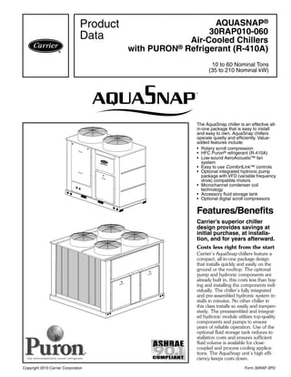
  • 1. Copyright 2010 Carrier Corporation Form 30RAP-3PD The AquaSnap chiller is an effective all- in-one package that is easy to install and easy to own. AquaSnap chillers operate quietly and efficiently. Value- added features include: • Rotary scroll compression • HFC Puron® refrigerant (R-410A) • Low-sound AeroAcoustic™ fan system • Easy to use ComfortLink™ controls • Optional integrated hydronic pump package with VFD (variable frequency drive) compatible motors • Microchannel condenser coil technology • Accessory fluid storage tank • Optional digital scroll compressors Features/Benefits Carrier’s superior chiller design provides savings at initial purchase, at installa- tion, and for years afterward. Costs less right from the start Carrier’s AquaSnap chillers feature a compact, all-in-one package design that installs quickly and easily on the ground or the rooftop. The optional pump and hydronic components are already built in; this costs less than buy- ing and installing the components indi- vidually. The chiller’s fully integrated and pre-assembled hydronic system in- stalls in minutes. No other chiller in this class installs so easily and inexpen- sively. The preassembled and integrat- ed hydronic module utilizes top-quality components and pumps to ensure years of reliable operation. Use of the optional fluid storage tank reduces in- stallation costs and ensures sufficient fluid volume is available for close- coupled and process cooling applica- tions. The AquaSnap unit’s high effi- ciency keeps costs down. AQUASNAP® 30RAP010-060 Air-Cooled Chillers with PURON® Refrigerant (R-410A) 10 to 60 Nominal Tons (35 to 210 Nominal kW) Product Data a30-4827 a30-4826
  • 2. 2 AquaSnap® chillers make noise in the marketplace, not the workplace. The AquaSnap chiller’s low-sound AeroAcoustic™ fan produces up to half the sound level of propeller fans. Much of the noise reduction is in frequencies where noise is most annoying, which makes AquaSnap chillers ideal for sound-sensitive environments. When lower ambient temperatures allow part-load operation or during sched- uled nighttime operation, the units op- erate with fewer fans and become even quieter. AquaSnap chillers are quiet during the day and even quieter at night. The savings will continue to mount Besides costing less to buy and install, AquaSnap chillers are also more af- fordable to operate. Carrier’s Aqua Series chillers are our most efficient air-cooled models. The AquaSnap chiller provides full-load EER (Energy Efficiency Ratio) up to 10.5 and IPLV (integrated part-load value) up to 15.3. AquaSnap chillers use ultra-quiet, high- efficiency rotary scroll compressors, operated in single (sizes 010 and 015) and tandem (sizes 018 to 060) per in- dependent circuit for greater efficiency at partial loads. Electronic expansion valve (EXV) allows for precise control through all operating ranges, resulting in higher efficiency and improved reliability. Proven reliability that’s built in Thousands of AquaSnap chillers are already in service around the world. This field-proven design is backed by a 12-month warranty that includes the hydronic system. The compressors are maintenance-free and protected by an auto-adaptive control that minimizes compressor wear. Unit sizes 035 and up have two independent refrigerant circuits. Year-round operation is standard, from –20 F (–29 C) (with optional cooler heater, low ambient control, and wind baffles) to 120 F (50 C). Rotary scroll compressors provide smooth, quiet and reliable operation. All-in-one package AquaSnap chillers provide the most comprehensive chilled water circuit available for any air-cooled chiller. Included is a brazed plate direct expansion cooler that may be remote- mounted. The cooler is also completely drainable with factory-installed vents and drains. Electronic thermal-dispersion flow switch is included with the cool- er. The switch is factory installed and tested and contains no moving parts for high reliability. Optional integrated hydronics package is more than just a pump, it is an entire chilled water system, including: • Single/dual pumps up to 7.5 hp and 120 ft head • Regular strainer • Cleanout strainer • Flow regulator • Freeze protection to –20 F (–29 C) (with freeze protection option) • Heaters • Required piping • Pressure/temperature taps • Isolation valves for dual pump systems • VFD compatibility The factory-installed and tested hy- dronics package provides faster, sim- pler and less expensive installation. Digital scroll compressors are available as a factory-installed option. These allow for incremental unloading with capacity modulation to better match building load when compared to standard scroll compressors. Environmentally sound Carrier’s Puron® refrigerant (R-410A) enables you to make a responsible de- cision in the protection of the earth’s ozone layer. Puron refrigerant is an HFC refrigerant that does not contain chlorine that is damaging to the ozone layer. Puron refrigerant is unaffected by the Montreal Protocol. Puron refrig- erant is a safe, non-toxic*, efficient and environmentally sound refrigerant for the future. Durable construction The 30RAP chillers have a structurally sound base that can be point-loaded, therefore, no perimeter base rail is re- quired. All 30RAP units have weather- ized cabinets constructed of heavy-duty galvanized steel with exterior panels painted with corrosion-resistant baked enamel. Inside and outside surfaces are protected to ensure long life and good appearance. The durable, galvanized steel, painted components exceed the requirements of the 500-hour salt spray test per ASTM (American Soci- ety for Testing and Materials) B117. ComfortLinkTM controls speak your language The ComfortLink controls communi- cate in plain English, making it as easy as possible to monitor and control each AquaSnap chiller while accurately maintaining fluid temperatures. The large scrolling marquee display acts as a window into the unit’s operation, providing easy-to-read information about chiller performance and over 15 diagnostic functions. Carrier 30 Series chillers’ ComfortLink controls provide features such as chilled water temperature reset, demand limiting, compressor wear minimization and protection, temperature and pressure displays and diagnostic functions. These controls result in higher chiller reliability, simplified training and more productive service calls with corre- spondingly lower operational and maintenance costs. Carrier’s exclusive accessory hand- held Navigator™ display provides con- venience and powerful information in the palm of your hand. The Navigator display helps technicians to quickly diagnose problems and even prevent them from occurring. All AquaSnap units are ready to be used with the Carrier Comfort Network® (CCN) system. AquaSnap units minimize the impact on your footprint, as well as your bottom line The integrated hydronics and the chilled fluid storage tank’s placement under the chiller minimize the foot- print, allowing easy installation almost anywhere. Novation® heat exchanger technology The Novation heat exchanger design with microchannel (MCHX) condenser coil is a robust, cost effective alterna- tive to traditional coil design. These coils are offered coated or uncoated to match coil protection to site condi- tions. The Carrier Electronic Catalog (E-Cat) can be used to determine whether or not corrosion protection is recommended for particular applica- tions in coastal/marine environments. Features/Benefits (cont) * Under ASHRAE Standard 34-1992, R-410A is classified as an A1 refrigerant.
  • 3. 3 Following the input of the requested data, the E-Cat program output will ad- vise the appropriate coil to be used. Other factors described in "Selection Guide: Environmental Corrosion Pro- tection, Novation Heat Exchanger with Microchannel Coil Technology" catalog number 04-581042-01 must also be considered to determine if corrosion protection is required. Microchannel coils are more robust than other coil types, making them easier to clean without causing damage to the coil. Due to the compact all aluminum design, microchannel coils will reduce average unit operating weight by 25% compared to the previous 30RA units. The streamlined MCHX coil design also reduces refrigerant charge by an average of 60% compared to the pre- vious 30RA units. Run Status Service Test Temperature Pressures Setpoints Inputs Outputs Configuration Time Clock Operating Modes Alarms Alarm Status ENTER MODE ESCAPE PROPELLER FANAEROACOUSTIC FAN 1/3 OCTAVE BAND CENTER FREQUENCY (Hz) SOUNDPOWER[dB(A)] AEROACOUSTIC™ FAN vs. PROPELLER FAN PENETRATES BUILDING STRUCTURE 25 40 63 130 168 250 400 630 1080 1600 2400 4000 6300 8000 90 85 80 75 70 65 60 55 50 Run Status Service Test Tem peratures Pressures Setpoints Inputs Outputs Configuration Time Clock Operating ModesAlarms ENTER ESC MODE Alarm Status ComfortLink SCROLLING MARQUEE DISPLAY NAVIGATOR™ DISPLAY MODULE OPTIONAL HYDRONIC PACKAGE LOW-SOUND AEROACOUSTIC FAN WITH NIGHTTIME LOW SOUND AEROACOUSTIC FAN VS PROPELLER FAN TUBES FINS MICROCHANNELS MANIFOLD NOVATION® HEAT EXCHANGER TECHNOLOGY WITH MICROCHANNEL CONDENSER COILS a30-4860
  • 4. 4 Table of contents Page Features/Benefits . . . . . . . . . . . . . . . . . . . . . . . . . . . . . . . . . . . . . . . . . . .1-3 Model Number Nomenclature . . . . . . . . . . . . . . . . . . . . . . . . . . . . . . . . . . . 4 AHRI Capacity Ratings . . . . . . . . . . . . . . . . . . . . . . . . . . . . . . . . . . . . . . . . 5 Physical Data . . . . . . . . . . . . . . . . . . . . . . . . . . . . . . . . . . . . . . . . . . . . . .6-8 Options and Accessories . . . . . . . . . . . . . . . . . . . . . . . . . . . . . . . . . . . . .9,10 Base Unit Dimensions . . . . . . . . . . . . . . . . . . . . . . . . . . . . . . . . . . . . .11-13 Accessory Dimensions . . . . . . . . . . . . . . . . . . . . . . . . . . . . . . . . . . . . .14-16 Selection Procedure . . . . . . . . . . . . . . . . . . . . . . . . . . . . . . . . . . . . . . . . . 17 Performance Data . . . . . . . . . . . . . . . . . . . . . . . . . . . . . . . . . . . . . . . .17-34 Typical Piping and Wiring . . . . . . . . . . . . . . . . . . . . . . . . . . . . . . . . . . .35-37 Electrical Data . . . . . . . . . . . . . . . . . . . . . . . . . . . . . . . . . . . . . . . . . . .38-45 Controls . . . . . . . . . . . . . . . . . . . . . . . . . . . . . . . . . . . . . . . . . . . . . . .46-48 Typical Control Wiring Schematic . . . . . . . . . . . . . . . . . . . . . . . . . . . . . . . 49 Application Data . . . . . . . . . . . . . . . . . . . . . . . . . . . . . . . . . . . . . . . . .50-55 Guide Specifications . . . . . . . . . . . . . . . . . . . . . . . . . . . . . . . . . . . . . . .56-60 Model number nomenclature P 0 0 030RA 0 66 D –010 30RA – Air-Cooled AquaSnap Chiller Refrigerant Type P – Puron Revision Level – – Current Revision Level Unit Sizes 010 025 045 015 030 050 018 035 055 020 040 060 Voltage 1 – 575-3-60 2 – 380-3-60 5 – 208/230-3-60 6 – 460-3-60 Condenser Coil/Low Sound Options 5 – MCHX, Value Sound Fan 6 – MCHX, E-coat, Value Sound Fan D – MCHX, AeroAcoustic™ Fan F – MCHX, E-coat, AeroAcoustic Fan J – MCHX, AeroAcoustic Fan, Ultra-Low Sound K – MCHX, E-coat, AeroAcoustic Fan, Ultra-Low Sound Hydronic System 0 – No Pump 1 – Single Pump, 1 Hp 2 – Single Pump, 1.5 Hp 3 – Single Pump, 2 Hp 4 – Single Pump, 3 Hp 5 – Single Pump, 5 Hp 6 – Single Pump, 5 Hp High Head 7 – Single Pump, 7.5 Hp 8 – Dual Pump, 1 Hp 9 – Dual Pump, 1.5 Hp B – Dual Pump, 2 Hp C – Dual Pump, 3 Hp D – Dual Pump, 5 Hp F – Dual Pump, 5 Hp High Head G – Dual Pump, 7.5 Hp Ambient/Capacity Control/Interrupt Options 0 – Std Comp, Std Interrupt 1 – Hot Gas Bypass, Std Interrupt 2 – Digital Comp, Std Interrupt 3 – Std Comp, High SCCR 4 – Hot Gas Bypass, High SCCR 5 – Digital Comp, High SCCR 6 – Low Ambient, Std Comp, Std Interrupt 7 – Low Ambient, Hot Gas Bypass, Std Interrupt 8 – Low Ambient, Digital Comp, Std Interrupt 9 – Low Ambient, Std Comp, High SCCR B – Low Ambient, Hot Gas Bypass, High SCCR C – Low Ambient, Digital Comp, High SCCR Electrical Options 0 – No Disconnect, No Cooler Heater 1 – No Disconnect, Cooler Heater D – Non-Fused Disconnect, No Cooler Heater F – Non-Fused Disconnect, Cooler Heater Controls/Communications Options 0 – Std 5 – EMM B – EMM, GFI Packaging/Security Options 0 – Std Packaging 4 – Security Grilles/Hail Guards Only 8 – Skid Only D – Skid, Security Grilles/Hail Guards J – Skid, Top Crate, Bag N – Skid, Top Crate, Bag, Security Grilles/Hail Guards® AQUASNAP® CHILLER MODEL NUMBER DESIGNATION LEGEND EMM — Energy Management Module GFI — Ground Fault Interrupting MCHX — Microchannel Heat Exchanger SCCR — Short Circuit Current Rating Quality Assurance Certified to ISO 9001: 2000 a30-5120
  • 5. 5 LEGEND * Air Conditioning, Heating, and Refrigeration Institute. NOTE: Based on AHRI-550/590 standard rating conditions. Ratings are for standard chillers only. Ratings do not include options. UNIT 30RAP CAPACITY COMPRESSOR POWER INPUT (kW) FAN POWER (kW) TOTAL POWER (kW) FULL LOAD IPLV COOLER FLOW RATE COOLER WATER PRESSURE DROP Tons kW EER COP EER COP GPM L/s Ft wg kPa 010 10.5 36.8 10.7 1.2 12.0 10.5 3.1 14.5 4.2 25.1 1.6 13.7 40.9 015 14.0 49.2 15.6 1.3 16.8 10.0 2.9 13.1 3.8 33.6 2.1 15.7 46.8 018 16.1 56.6 15.6 3.0 18.6 10.4 3.0 14.3 4.2 38.6 2.4 15.6 46.5 020 18.8 66.1 19.1 2.9 21.9 10.3 3.0 14.0 4.1 45.2 2.9 14.2 42.4 025 23.4 82.3 24.5 2.8 27.4 10.3 3.0 15.0 4.4 56.3 3.6 17.8 53.1 030 27.6 97.1 30.9 2.7 33.6 9.9 2.9 14.7 4.3 66.3 4.2 20.9 62.3 035 34.4 121.0 35.9 3.8 39.7 10.4 3.0 15.2 4.5 82.5 5.2 13.2 39.4 040 38.9 136.8 42.3 3.8 46.1 10.1 3.0 15.2 4.5 93.4 5.9 13.8 41.2 045 43.1 151.6 48.6 3.4 52.0 10.0 2.9 15.3 4.5 103.4 6.5 15.3 45.6 050 47.3 166.3 53.1 3.8 57.0 10.0 2.9 14.5 4.2 113.5 7.2 19.1 57.0 055 51.8 182.2 56.4 5.3 61.7 10.1 3.0 14.5 4.2 124.2 7.8 17.6 52.5 060 56.0 196.9 60.8 5.3 66.2 10.2 3.0 14.3 4.2 134.4 8.5 20.5 61.2 COP— Coefficient of Performance EER — Energy Efficiency Ratio IPLV — Integrated Part Load Value AHRI* capacity ratings
  • 6. 6 ENGLISH LEGEND *All units have Victaulic connections, sized for IPS Carbon Steel piping. †Flow switch and strainer are standard on all units, with or without hydronic package. UNIT 30RAP 010 015 018 020 025 030 035 040 045 050 055 060 OPERATING WEIGHT (lb) MCHX Condenser Coil, No Pump 704 718 1125 1133 1242 1283 2163 2185 2238 2263 2369 2375 MCHX Condenser Coil, Single Pump 866 880 1288 1296 1405 1446 2507 2529 2582 2606 2713 2719 MCHX Condenser Coil, Dual Pump 1029 1043 1450 1458 1567 1608 2850 2872 2925 2950 3056 3062 REFRIGERANT TYPE R-410A, EXV Controlled System Total Refrigerant Charge (lb) 8.6 9.6 14.6 15.2 16.7 17.6 29.2 29.9 33.5 33.7 34.3 34.5 Refrigerant Charge (lb) Ckt A/Ckt B 8.6/— 9.6/— 14.6/— 15.2/— 16.7/— 17.6/— 14.3/14.9 14.9/15.0 16.5/17.0 16.7/17.0 16.9/17.4 17.1/17.4 COMPRESSORS Scroll, Hermetic Quantity 1 1 2 2 2 2 4 4 4 4 4 4 Speed (Rpm) 3500 (Qty, Tons) Ckt A (1) 11 (1) 15 (2) 9 (2) 10 (2) 13 (2) 15 (2) 10 (2) 10 (2) 11 (2) 13 (2) 13 (2) 15 (Qty, Tons) Ckt B — — — — — — (2) 9 (2) 11 (2) 13 (2) 13 (2) 15 (2) 15 Oil Charge (Pt) Ckt A/Ckt B 6.9/— 6.9/— 13.8/— 13.8/— 13.8/— 13.8/— 13.8/13.8 13.8/13.8 13.8/13.8 13.8/13.8 13.8/13.8 13.8/13.8 No. Capacity Steps Standard 1 1 2 2 2 2 4 4 4 4 4 4 With Hot Gas Bypass — — 3 3 3 3 5 5 5 5 5 5 Digital Compressor Option 13 13 — 22 22 22 44 44 44 44 44 44 Minimum Capacity Step (%) Standard 100 100 50 50 50 50 23 23 24 25 23 25 With Hot Gas Bypass — — 20 24 29 32 9 11 12 14 13 16 Digital Compressor Option 20 20 — 15 15 15 8 8 8 8 8 8 Capacity (%) Circuit A 100 100 100 100 100 100 54 47 47 50 46 50 Circuit B — — — — — — 46 53 53 50 54 50 COOLER Brazed, Direct-Expansion Plate Heat Exchanger Weight (lb) (empty) 22.4 27.5 31.8 40.3 46.3 80.6 99.4 117.9 125.3 137.5 160.4 160.4 Net Fluid Volume (gal) 0.6 0.8 0.9 1.2 1.4 2.0 2.6 3.3 3.5 4.1 5.0 5.0 Maximum Refrigerant Pressure (psig) 505 505 505 505 505 565 565 565 565 565 565 565 Maximum Water-Side Pressure Without Pump(s) (psig) 300 300 300 300 300 300 300 300 300 300 300 300 Maximum Water-Side Pressure With Pump(s) (psig) 150 150 150 150 150 150 150 150 150 150 150 150 CHILLER WATER CONNECTIONS (in.) Inlet and Outlet, Victualic (IPS Carbon Steel)* 2 2 2 2 2 2 21/2 21/2 21/2 21/2 21/2 21/2 Drain (NPT) 1/2 1/2 1/2 1/2 1/2 1/2 1/2 1/2 1/2 1/2 1/2 1/2 CONDENSER FANS Standard Low-Sound AeroAcoustic™ Type Plastic Type, Axial, Vertical Discharge Fan Speed (Rpm) 850 850 850 850 850 850 850 850 850 850 850 850 No. Blades...Diameter (in.) 9...30 9...30 9...30 9...30 9...30 9...30 9...30 9...30 9...30 9...30 9...30 9...30 No. Fans 1 1 2 2 2 2 3 3 3 3 4 4 Total Airflow (Cfm) 9400 9400 17,500 17,500 19,400 19,400 29,600 29,500 29,300 30,500 38,800 38,800 Optional Value Sound Type Propeller Type, Axial, Vertical Discharge Fan Speed (Rpm) 1140 1140 1140 1140 1140 1140 1140 1140 1140 1140 1140 1140 No. Blades...Diameter (in.) 4...30 4...30 4...30 4...30 4...30 4...30 4...30 4...30 4...30 4...30 4...30 4...30 No. Fans 1 1 2 2 2 2 3 3 3 3 4 4 Total Airflow (Cfm) 12,600 12,600 23,400 23,400 26,000 26,000 39,800 39,600 39,300 41,000 52,100 52,100 CONDENSER COILS Novation® MCHX Aluminum Tube, Aluminum Fin Quantity (Ckt A/Ckt B) 1/— 1/— 1/— 1/— 1/— 1/— 1/1 1/1 1/1 1/1 1/1 1/1 Total Face Area (sq ft) 17 17 26 26 33 33 53 53 66 66 66 66 Maximum Refrigerant Pressure (psig) 656 656 656 656 656 656 656 656 656 656 656 656 HYDRONIC MODULE (Optional)† Pump(s), Strainer with Blowdown Valve, Expansion Tank, Pressure Taps, Drain and Vent Plugs, Flow Switch, and Balance Valve Pump Single or Dual, Centrifugal Monocell Pump(s), 3500 Rpm. Dual pumps with check valves and isolation valves. Expansion Tank Volume (gal) Total/Acceptance 4.4/3.2 10.3/10.3 CHASSIS DIMENSIONS (ft - in.) Length 5-7 5-7 7-5 7-5 7-5 7-5 7-5 7-5 7-5 7-5 7-5 7-5 Width 3-5 3-5 3-5 3-5 3-5 3-5 7-9 7-9 7-9 7-9 7-9 7-9 Height 5-6 5-6 5-6 5-6 6-6 6-6 5-6 5-6 6-6 6-6 6-6 6-6 EXV — Electronic Expansion Valve MCHX — Microchannel Heat Exchanger Physical data
  • 7. 7 SI LEGEND *All units have Victaulic connections, sized for IPS Carbon Steel piping. †Flow switch and strainer are standard on all units, with or without hydronic package. UNIT 30RAP 010 015 018 020 025 030 035 040 045 050 055 060 OPERATING WEIGHT (kg) MCHX Condenser Coil, No Pump 319 326 510 514 564 582 981 991 1015 1026 1075 1077 MCHX Condenser Coil, Single Pump 393 399 584 588 637 656 1137 1147 1171 1182 1231 1233 MCHX Condenser Coil, Dual Pump 467 473 658 661 711 729 1293 1303 1327 1338 1386 1389 REFRIGERANT TYPE R-410A, EXV Controlled System Total Refrigerant Charge (kg) 3.9 4.4 6.6 7.1 7.6 8.0 13.4 13.6 15.6 15.7 16.0 16.1 Refrigerant Charge (kg) Ckt A/Ckt B 3.9/— 4.4/— 6.6/— 7.1/— 7.6/— 8.0/— 6.8/6.7 6.8/6.8 7.8/7.8 7.8/7.8 7.9/8.1 8.1/8.1 COMPRESSORS Scroll, Hermetic Quantity 1 1 2 2 2 2 4 4 4 4 4 4 Speed (R/s) 58.3 (Qty, kW) Ckt A (1) 38 (1) 53 (2) 32 (2) 35 (2) 46 (2) 53 (2) 35 (2) 35 (2) 38 (2) 46 (2) 46 (2) 53 (Qty, kW) Ckt B — — — — — — (2) 32 (2) 38 (2) 46 (2) 46 (2) 53 (2) 53 Oil Charge (L) Ckt A/Ckt B 3.3/— 3.3/— 6.5/— 6.5/— 6.5/— 6.5/— 6.5/6.5 6.5/6.5 6.5/6.5 6.5/6.5 6.5/6.5 6.5/6.5 No. Capacity Steps Standard 1 1 2 2 2 2 4 4 4 4 4 4 With Hot Gas Bypass — — 3 3 3 3 5 5 5 5 5 5 Digital Compressor Option 13 13 — 22 22 22 44 44 44 44 44 44 Minimum Capacity Step (%) Standard 100 100 50 50 50 50 23 23 24 25 23 25 With Hot Gas Bypass — — 20 24 29 32 9 11 12 14 13 16 Digital Compressor Option 20 20 — 15 15 15 8 8 8 8 8 8 Capacity (%) Circuit A 100 100 100 100 100 100 54 47 47 50 46 50 Circuit B — — — — — — 46 53 53 50 54 50 COOLER Brazed, Direct-Expansion Plate Heat Exchanger Weight (kg) (empty) 10.1 12.5 14.4 18.3 21.0 36.6 45.1 53.5 56.8 62.4 72.8 72.8 Net Fluid Volume (L) 2.3 3.0 3.4 4.5 5.3 7.6 9.8 12.5 13.2 15.5 18.9 18.9 Maximum Refrigerant Pressure (kPa) 3482 3482 3482 3482 3482 3896 3896 3896 3896 3896 3896 3896 Maximum Water-Side Pressure Without Pump(s) (kPa) 2068 2068 2068 2068 2068 2068 2068 2068 2068 2068 2068 2068 Maximum Water-Side Pressure With Pump(s) (kPa) 1034 1034 1034 1034 1034 1034 1034 1034 1034 1034 1034 1034 CHILLER WATER CONNECTIONS (in.) Inlet and Outlet, Victualic (IPS Carbon Steel)* 2 2 2 2 2 2 21/2 21/2 21/2 21/2 21/2 21/2 Drain (NPT) 1/2 1/2 1/2 1/2 1/2 1/2 1/2 1/2 1/2 1/2 1/2 1/2 CONDENSER FANS Standard Low-Sound AeroAcoustic™ Type Plastic Type, Axial, Vertical Discharge Fan Speed (R/s) 14.2 14.2 14.2 14.2 14.2 14.2 14.2 14.2 14.2 14.2 14.2 14.2 No. Blades...Diameter (mm) 9...762 9...762 9...762 9...762 9...762 9...762 9...762 9...762 9...762 9...762 9...762 9...762 No. Fans 1 1 2 2 2 2 3 3 3 3 4 4 Total Airflow (L/s) 4400 4400 8300 8300 9200 9200 14,000 14,000 13,800 14,400 18,300 18,300 Optional Value Sound Type Propeller Type, Axial, Vertical Discharge Fan Speed (R/s) 19.0 19.0 19.0 19.0 19.0 19.0 19.0 19.0 19.0 19.0 19.0 19.0 No. Blades...Diameter (mm) 4...762 4...762 4...762 4...762 4...762 4...762 4...762 4...762 4...762 4...762 4...762 4...762 No. Fans 1 1 2 2 2 2 3 3 3 3 4 4 Total Airflow (L/s) 5900 5900 11,000 11,000 12,300 12,300 18,800 18,700 18,500 19,400 24,600 24,600 CONDENSER COILS Novation® MCHX Aluminum Tube, Aluminum Fin Quantity (Ckt A/Ckt B) 1/— 1/— 1/— 1/— 1/— 1/— 1/1 1/1 1/1 1/1 1/1 1/1 Total Face Area (sq m) 1.6 1.6 2.4 2.4 3.1 3.1 4.9 4.9 6.1 6.1 6.1 6.1 Maximum Refrigerant Pressure (kPa) 4523 4523 4523 4523 4523 4523 4523 4523 4523 4523 4523 4523 HYDRONIC MODULE (Optional)† Pump(s), Strainer with Blowdown Valve, Expansion Tank, Pressure Taps, Drain and Vent Plugs, Flow Switch, and Balance Valve Pump Single or Dual, Centrifugal Monocell Pump(s), 3500 Rpm. Dual pumps with check valves and isolation valves. Expansion Tank Volume (L) Total/Acceptance 17.4/12.3 39.0/39.0 CHASSIS DIMENSIONS (mm) Length 1689 1689 2242 2242 2242 2242 2248 2248 2248 2248 2248 2248 Width 1029 1029 1025 1025 1025 1025 2350 2350 2350 2350 2350 2350 Height 1689 1689 1689 1689 1994 1994 1689 1689 1994 1994 1994 1994 EXV — Electronic Expansion Valve MCHX — Microchannel Heat Exchanger
  • 8. 8 UNIT WEIGHTS STANDARD UNITS SINGLE PUMP UNITS DUAL PUMP UNITS 30RAP SIZE POUNDS 30RAP SIZE KILOGRAMS A B C D Total Weight A B C D Total Weight 010 188 209 161 146 704 010 85.5 94.6 73.1 66.1 319.3 015 193 213 163 149 718 015 87.7 96.4 74.1 67.4 325.5 018 363 264 209 288 1125 018 164.9 119.9 94.9 130.6 510.3 020 365 266 211 290 1133 020 165.8 120.8 95.8 131.5 513.9 025 393 290 237 321 1242 025 178.3 131.8 107.7 145.7 563.5 030 405 301 246 331 1283 030 183.7 136.3 111.6 150.4 582.0 035 652 730 413 369 2163 035 295.7 331.0 187.2 167.2 981.1 040 704 697 390 394 2185 040 319.4 316.3 176.9 178.5 991.1 045 675 758 425 379 2238 045 306.3 344.0 193.0 171.9 1015.1 050 732 724 401 405 2263 050 332.2 3328.4 181.8 183.9 1026.3 055 744 762 437 427 2369 055 337.4 345.5 198.2 193.5 1074.6 060 746 762 438 429 2375 060 338.4 345.8 198.6 194.5 1077.3 30RAP SIZE POUNDS 30RAP SIZE KILOGRAMS A B C D Total Weight A B C D Total Weight 010 215 264 213 174 866 010 97.6 119.8 96.7 78.9 393.0 015 220 268 215 177 880 015 99.8 121.6 97.7 80.2 399.3 018 404 306 249 329 1288 018 183.4 138.7 112.8 149.2 584.0 020 406 308 251 331 1296 020 184.3 139.6 113.7 150.1 587.6 025 434 332 277 362 1405 025 196.9 150.5 125.6 164.2 637.2 030 446 342 286 372 1446 030 202.2 155.1 129.5 168.9 655.7 035 740 814 499 453 2507 035 335.6 369.4 226.3 205.6 1137.0 040 791 783 475 480 2529 040 358.8 355.3 215.4 217.5 1147.0 045 763 843 512 463 2582 045 346.3 382.3 232.1 210.2 1171.0 050 819 810 486 491 2606 050 371.6 367.4 220.4 222.9 1182.2 055 831 847 522 512 2713 055 376.9 384.3 236.9 232.3 1230.5 060 833 848 523 514 2719 060 378.0 384.6 237.3 233.3 1233.2 30RAP SIZE POUNDS 30RAP SIZE KILOGRAMS A B C D Total Weight A B C D Total Weight 010 242 319 266 202 1029 010 109.9 144.8 120.5 91.5 466.7 015 247 323 268 205 1043 015 112.1 146.6 121.4 92.8 473.0 018 445 347 288 370 1450 018 202.0 157.4 130.7 167.7 657.7 020 447 349 290 372 1458 020 202.9 158.3 131.6 168.6 661.3 025 475 373 316 403 1567 025 215.5 169.2 143.5 182.7 710.9 030 487 383 325 413 1608 030 220.8 173.8 147.4 187.3 729.4 035 828 899 585 538 2850 035 375.5 407.9 265.3 244.2 1292.9 040 878 869 560 565 2872 040 398.2 394.2 254.0 256.5 1302.9 045 851 928 598 548 2925 045 386.2 420.8 271.1 248.8 1326.9 050 906 896 571 577 2950 050 411.0 406.4 258.9 261.8 1338.1 055 918 933 607 598 3056 055 416.4 423.2 275.6 271.2 1386.3 060 920 933 608 600 3062 060 417.5 423.4 276.0 272.1 1389.1 B A C D CONTROL BOX SIDE B A C D CONTROL BOX SIDE 30RAP010-030 UNITS 30RAP035-060 UNITS a30-4861 NOTE: When the accessory storage tank is employed, the value for total weight increases (to be added to the weights shown above) by 1673 pounds (759 kg) on 30RAP010-015, by 2193 pounds (995 kg) on 30RAP018-030, and by 4361 pounds (1978 kg) on 30RAP035-060. Even with the storage tank, all 30RAP chillers require only 4-point support. Physical data (cont)
  • 9. 9 * Sponsored by ASHRAE (American Society of Heating, Refrigeration, and Air Conditioning Engineers). Factory-installed options Novation® heat exchanger technology microchan- nel coil (aluminum fin/aluminum tube) e-coat con- denser is available for optimum durability. Novation heat exchangers with microchannel coil technology are offered coated or uncoated to match coil protection to site condi- tions. The Carrier Electronic Catalog (E-Cat) can be used to determine whether or not corrosion protection is recom- mended for particular applications in coastal/marine envi- ronments. Following the input of the requested data, the E- Cat program output will advise the appropriate coil to be used. Other factors described in "Selection Guide: Environ- mental Corrosion Protection, Novation Heat Exchanger with Microchannel Coil Technology" catalog number 04- 581042-01 must also be considered to determine if corro- sion protection is required. Value sound fans provide a metal, propeller-type fan sys- tem which is cost-effective when compared to the low- sound aero-acoustic fan system. This factory-installed fan option is compatible with the Motormaster® V option. Ultra-low sound provides a combination of low sound AeroAcoustic™ fans with sound blankets. Digital compressor control allows incremental unload- ing for a closer match to building load. This option is not available on the 018 size unit. High short circuit current rating provides a short cir- cuit current rating protection for the unit up to 65,000 A on 460-v, 380-v, and 208/230-v units or 25,000 A on 575-v units. Motormaster® V low-ambient control provides con- trol of fan motor operation to maintain head pressure at low outdoor ambient temperatures down to –20 F (–29 C) This option also requires field-installed wind baffles. This option is also available as an accessory. This option is a standard feature on all 30RAP010 and 015 chillers. Non-fused disconnect includes factory-installed non- fused disconnect capability for power and control located at the unit. Energy management module provides energy manage- ment capabilities to minimize chiller energy consumption. Several features are provided with this module including leaving fluid temperature reset, cooling set point reset or demand limit control from a 4 to 20 mA signal, 2-point demand limit control (from 0 to 100%) activated by a remote contact closure, and discrete input for “Ice Done” indication for ice storage system interface. The EMM is also available as an accessory. Freeze protection with cooler heaters provides protec- tion from cooler freeze-up to –20 F (–29 C). GFI convenience outlet is a factory-installed conve- nience outlet that includes 4-amp GFI (ground fault inter- rupter) receptacle with independent fuse protection. Convenience outlet is 115-v female receptacle. This option is also available as an accessory. Hydronic pump package option adds circulating pumps, complete with controls, contactor, VFD compati- ble motors, and insulated expansion tank. Available in sin- gle or dual (lead/lag controlled) cooler pump versions, with ITEM FACTORY-INSTALLED OPTION FIELD-INSTALLED ACCESSORY Condenser Coil and Sound Options MCHX E-Coat X Low Sound Compressor Blankets X Value Sound Fans X Ultra-Low Sound X Controls/Communication Options BACnet* Translator Control X Chillervisor System Manager III Multi-Unit Control X Energy Management Module (EMM) X X LON (Local Operating Network) Translator Control X Navigator™ Display X Remote Enhanced Display X Touch Pilot™ Display X Cooler Options Freeze Protection — Cooler Heaters X Remote Cooler Kit X Electrical Options Unit-Mounted Main Disconnect, Non-Fused X GFI Convenience Outlet (115 v) X X High SCCR (Short Circuit Current Rating) X Hydronics Option Hydronic Pump Package X Fluid Storage Tank X Refrigeration Circuit Options Low Ambient Temperature Head Pressure Control X X Hot Gas Bypass (not available on sizes 010 and 015) X X Digital Compressor (not available on size 018) X Security/Packaging Options Security Grilles/Hail Guards X X Vibration Isolation X Wind Baffles X Options and accessories
  • 10. 10 total dynamic head external to the chiller from approxi- mately 15 to 120 ft (4.6 to 36.6 m). Hot gas bypass option allows additional capacity reduc- tion for unit operation down below the minimum standard step of capacity. This option is not available on units with the digital compressor option or on the 30RAP010 and 015 units. This option is also available as an accessory on all 30RAP units without digital compressors. Security grilles/hail guards consist of louvered, sheet metal panels which securely fasten to the chiller and pro- vide condenser coil protection against hail and physical damage. This option is also available as an accessory. Field-installed accessories BACnet translator control provides an interface be- tween the unit and a BACnet Local Area Network (LAN, i.e., MS/TP EIA-485). Chillervisor System Manager III multi-unit control accessory allows sequencing of between two and eight chillers in parallel. Pump control is also provided. Energy management module provides energy manage- ment capabilities to minimize chiller energy consumption. Several features are provided with this module including leaving fluid temperature reset, cooling set point reset or demand limit control from a 4 to 20 mA signal, 2-point demand limit control (from 0 to 100%) activated by a remote contact closure, and discrete input for “Ice Done” indication for ice storage system interface. The EMM is also available as an option. LON (local operating network) translator control provides an interface between the unit and a local operat- ing network (i.e., LonWorks* FT-10A ANSI/EIA-709.1). Navigator™ display module provides a portable, hand held display module for convenient access to unit status, operation, configuration and troubleshooting diagnostics capability. The 4-line, 80-character LCD (liquid crystal display) display provides clear language information in English, French, Spanish or Portuguese. The weatherproof enclosure and industrial grade extension cord make the Navigator module ideally suited for outdoor applications. Magnets located on the back of the module allow attachment of any sheet metal component for hands free operation. Remote enhanced display accessory kit contains a remotely mounted 40-character per line, 16-line display panel for unit diagnostics. Touch Pilot™ display is a cost-effective, touch-screen, remote-mount device that can be used in lieu of the remote enhanced display. Motormaster® V low-ambient control provides con- trol of outdoor-fan motor operation to maintain head pres- sure at low outdoor ambient temperatures down to –20 F (–29 C). This accessory also requires field-installed wind baffles. This accessory is also available as a factory-installed option. This accessory is standard on 30RAP010 and 015 units. Chilled water storage tank provides a minimum of 4 gallons per ton loop storage capacity. Includes insulated steel shell tank, Victaulic pipe connections, electric tank heaters, electric cables, vent, drain, and enclosure to allow tank to be installed under the chiller to protect to –20 F (–29 C). The power supply for the storage tank is obtained from the chiller, so no separate power source is required for this accessory. Vibration isolation consists of field-installed 1/4-in. (0.64 cm) neoprene isolator pads (24-in. x 3-in.) (61.0 cm x 7.6 cm) that reduce vibration transmission from the com- pressor through the floor and into the conditioned space. Low sound compressor blankets reduce unit sound levels by providing an acoustic blanket on each compres- sor. Hot gas bypass accessory allows additional capacity re- duction for unit operation below the minimum standard step of capacity. This accessory is not available on units which have the digital compressor option. This field-in- stalled accessory is also available as a factory-installed op- tion, but the factory option is not available with digital com- pressors or unit sizes of 010 or 015. Remote cooler kit provides the additional hardware re- quired to remotely mount the cooler from the unit. There are limits to total separation of the unit to the cooler as well as vertical separation limits, and these are delineated in the accessory installation instructions. Never bury refrigerant piping on these or any other applications. GFI convenience outlet is a field-installed convenience outlet that includes a 4-amp GFI (ground fault interrupter) receptacle with independent fuse protection. The conve- nience outlet is a 115-v female receptacle. The GFI conve- nience outlet is also available as a factory-installed option. Security grilles/hail guards consist of louvered, sheet metal panels which securely fasten to the chiller and pro- vide condenser coil protection against hail and physical damage. Security grilles/hail guards are also available as a factory-installed option. Wind baffles facilitate operation down to –20 F (–29 C) when used in conjunction with low ambient temperature head pressure control. Options and accessories (cont) *Registered trademark of Echelon Corporation.
  • 11. 11 a30- 40.50[1028.7] FIELDPOWERENTRY SEENOTE#2 7/822.4[] 24.85 631.2[] 4.61 117.1[] SEENOTE#3 TYP. 1.0025.4[] SEENOTE#3 TYP. 1.0025.4[] 9.68245.9[] 15.43391.9[] 9.52 241.8[] 48[1219]MIN. 36[914]MIN. 42[1067] MIN. 36[914]MIN. 66.50[1689.1] RADIUS20[508] CONTROLBOX HINGEDACCESS 1.5038.1[]1.5038.1[] Y X H SEENOTE#5 UNIT CENTEROFGRAVITYUNITHEIGHTVICTAULICCONNECTIONS XYH(STANDARD)H(VALUESOUND)WATERIN/OUT STANDARD 30RA01018.40[467]37.80[960]66.5[1689]61.0[1549]2" 30RA01518.35[466]37.69[957]66.5[1689]61.0[1549]2" RIGHTSIDE VIEW CONTROLBOX HINGEDACCESS NOTES: 1.DONOTCAPOROTHERWISEOBSTRUCTTHE LIQUIDLINETEMPERATURERELIEF. 2.7/8[22.4]PILOTHOLEPROVIDEDFORLOCATINGFIELDPOWERWIRING. ACTUALHOLEREQUIREDDEPENDSONFIELDWIRESIZING. 3.0.437[11.10]HOLEUSEDFORMOUNTINGUNIT. 4.UNITMUSTHAVECLEARANCESASFOLLOWS: TOP-DONOTRESTRICT. COILSIDE-42[1067]FROMSOLIDSURFACE. PANELSIDE-48[1219]PERNEC. 5.SEETABLECOLUMNH;DIMENSIONFORSTANDARDFANORVALUE SOUNDFANOPTION. 6.CARRIERDOESNOTRECOMMENDINSTALLATIONINAPIT. 7.UNITCANBEHANDLEDUSINGTHEFORKTRUCKLIFTPOCKETS. 8.WATERCONNECTIONSRECESSED2-3/8INCHESINSIDEUNIT. DIMENSIONSIN[]AREINMILLIMETERS COMPRESSOR ACCESS COIL AREA AIRFLOW AIRFLOW FRONTVIEW PANELSIDE SEENOTE#4 COILSIDE SEENOTE#4 SERVICE ACCESS SERVICE CLEARANCE BORDER (NOTTOSCALE) TOPVIEW CG VALUESOUNDFANOPTION (PICTORIALLY) FIELDCONTROL WIRINGCONNECTIONS WATER-IN WATER-OUT FORK TRUCK POCKETS 9.DIMENSIONSAREININCHES. Base unit dimensions — 30RAP010,015
  • 13. 13 a30-4564 RADIUS20[508] CONTROLBOX HINGEDACCESS 88.50[2247.9] 1.50 38.1[] 1.50 38.1[] SEENOTE#3 TYP. 1.0025.4[]SEENOTE#3 TYP. 1.0025.4[] 4.63 117.6[] 27.98 710.7[] 7/8[22.4] FIELDPOWERENTRY SEENOTE#2 44.00 1117.6[] 11.20 284.5[] 31.74 806.2[] Y X H SEENOTE#5 42[1067]MIN. 48[1219]MIN. 42[1067]MIN. 48[1219]MIN. 92.50[2349.5] UNIT CENTEROFGRAVITYUNITHEIGHTVICTAULICCONNECTIONS XYH(STANDARD)H(VALUESOUND)WATERIN/OUT 30RA03536.45[926]46.08[1170]66.5[1689]61.0[1549]2-1/2" 30RA04036.24[921]44.03[1118]66.5[1689]61.0[1549]2-1/2" 30RA04536.24[921]46.15[1172]78.5[1994]73.0[1854]2-1/2" 30RA05036.00[914]44.00[1118]78.5[1994]73.0[1854]2-1/2" 30RA05536.48[927]44.60[1133]78.5[1994]73.0[1854]2-1/2" 30RA06036.50[927]44.56[1132]78.5[1994]73.0[1854]2-1/2" REARVIEW CONTROLBOX HINGEDACCESS CIRCUITA COMPRESSOR ACCESS COIL AREA AIRFLOW AIRFLOW FRONTVIEW CIRCUITB COMPRESSOR ACCESS TOPVIEW RIGHTVIEW COIL AREA SERVICE CLEARANCE BORDER (NOTTOSCALE) CG NOTES: 1.DONOTCAPOROTHERWISEOBSTRUCTTHE LIQUIDLINETEMPERATURERELIEF. 2.7/8[22.4]PILOTHOLEPROVIDEDFORLOCATINGFIELDPOWERWIRING. ACTUALHOLEREQUIREDDEPENDSONFIELDWIRESIZING. 3.0.437[11.10]HOLEUSEDFORMOUNTINGUNIT. 4.UNITMUSTHAVECLEARANCESASFOLLOWS: TOP-DONOTRESTRICT. COILSIDE-42[1067]FROMSOLIDSURFACE. PANELSIDE-48[1219]PERNEC. 5.SEETABLECOLUMNH;DIMENSIONFORSTANDARDFANORVALUE SOUNDFANOPTION. 6.CARRIERDOESNOTRECOMMENDINSTALLATIONINAPIT. 7.UNITCANBEHANDLEDUSINGTHEFORKTRUCKLIFTPOCKETS (MINIMUMOF60"FORKLENGTH). 8.WATERCONNECTIONSRECESSED4-1/2INCHESINSIDEUNIT. DIMENSIONSIN[]AREINMILLIMETERS VALUESOUNDFANOPTION (PICTORIALLYONLY) AIRFLOW FIELD CONTROL WIRING CONNECTIONS FORK TRUCK POCKETS NOTE:3OR4FANS PANELSIDE SEENOTE#4 COILSIDE SEENOTE#4 PANELSIDE SEENOTE#4 COILSIDE SEENOTE#4 WATER-IN WATER-OUT 9.DIMENSIONSAREININCHES. Base unit dimensions — 30RAP035-060
  • 17. 17 Carrier’s electronic catalog chiller selection program pro- vides quick, easy selection of Carrier chillers. The program considers specific temperature, fluid, flow requirements, system pressure drop (for proper pump selection, when required), as well as other factors, such as fouling and alti- tude correction. To select a 30RAP chiller, including optional pump package when required, use the NACO Packaged Chiller Builder Program. Performance data 50 1 65432 40 45 30 35 DROP(Ğ) 20 25 TERPRESSURE 10 15 WAT 0 5 0 10 20 30 40 50 60 70 80 90 100 110 120 130 140 150 GPM HEAT EXCHANGER PRESSURE DROP — 30RAP010-030 (ENGLISH) LEGEND 1 — 30RAP010 4 — 30RAP020 2 — 30RAP015 5 — 30RAP025 3 — 30RAP018 6 — 30RAP030a30-5122 Selection procedure
  • 18. 18 50 7 8 9 10 11 & 12 40 30 ROP(Ğ) 20 RPRESSUREDR 10 WATER 0 10 0 0 10 20 30 40 50 60 70 80 90 100 110 120 130 140 150 160 170 180 190 200 210 220 230 240 250 260 GPM LEGEND 7 — 30RAP035 10 — 30RAP050 8 — 30RAP040 11 — 30RAP055 9 — 30RAP045 12 — 30RAP060 HEAT EXCHANGER PRESSURE DROP — 30RAP035-060 (ENGLISH) a30-5123 150 1 65432 125 100 DROP(Kpa) 75 ERPRESSURED 25 50 WATE 0 25 0 1 2 3 4 5 6 7 8 9 10 LITERS/SECOND LEGEND 1 — 30RAP010 4 — 30RAP020 2 — 30RAP015 5 — 30RAP025 3 — 30RAP018 6 — 30RAP030 HEAT EXCHANGER PRESSURE DROP — 30RAP010-030 (SI) a30-5124 Performance data (cont)
  • 19. 19 150 7 8 9 10 11 & 12 125 100 DROP(Kpa) 75 TERPRESSURED 25 50 WAT 0 25 0 1 2 3 4 5 6 7 8 9 10 11 12 13 14 15 16 17 LITERS/SECOND LEGEND 7 — 30RAP035 10 — 30RAP050 8 — 30RAP040 11 — 30RAP055 9 — 30RAP045 12 — 30RAP060 HEAT EXCHANGER PRESSURE DROP — 30RAP035-060 (SI) a30-5125 50 1 2 3 4 5 6 40 45 30 35 DROP(Ğ) 20 25 TERPRESSURED 10 15 WAT 0 5 10 0 0 10 20 30 40 50 60 70 80 90 100 110 120 130 140 150 GPM UNIT PRESSURE DROP — NO HYDRONIC PACKAGE — 30RAP010-030 (ENGLISH) LEGEND 1 — 30RAP010 4 — 30RAP020 2 — 30RAP015 5 — 30RAP025 3 — 30RAP018 6 — 30RAP030 a30-5126
  • 20. 20 50 7 8 9 10 11 & 12 40 45 30 35 DROP(Ğ) 20 25 TERPRESSURED 10 15 WAT 0 5 10 0 0 10 20 30 40 50 60 70 80 90 100 110 120 130 140 150 160 170 180 190 200 210 220 230 240 250 260 GPM UNIT PRESSURE DROP — NO HYDRONIC PACKAGE — 30RAP035-060 (ENGLISH) LEGEND 7 — 30RAP035 10 — 30RAP050 8 — 30RAP040 11 — 30RAP055 9 — 30RAP045 12 — 30RAP060 a30-5127 150 1 2 3 4 5 6 125 100 DROP(Kpa) 75 ERPRESSURED 50 WATE 0 25 0 0 1 2 3 4 5 6 7 8 9 10 LITERS/SECOND UNIT PRESSURE DROP — NO HYDRONIC PACKAGE — 30RAP010-030 (SI) LEGEND 1 — 30RAP010 4 — 30RAP020 2 — 30RAP015 5 — 30RAP025 3 — 30RAP018 6 — 30RAP030 a30-5128 Performance data (cont)
  • 21. 21 150 7 8 9 10 11 & 12 125 100 DROP(Kpa) 75 ERPRESSURED 50 WATE 0 25 0 0 1 2 3 4 5 6 7 8 9 10 11 12 13 14 15 16 17 LITERS/SECOND UNIT PRESSURE DROP — NO HYDRONIC PACKAGE — 30RAP035-060 (SI) LEGEND 7 — 30RAP035 10 — 30RAP050 8 — 30RAP040 11 — 30RAP055 9 — 30RAP045 12 — 30RAP060 a30-5129 100 654321 80 90 60 70 ROP(Ğ) 40 50 RPRESSUREDR 30 40 WATER 10 20 0 0 10 20 30 40 50 60 70 80 90 100 110 120 130 140 150 160 170 GPM UNIT PRESSURE DROP — SINGLE PUMP HYDRONIC PACKAGE — 30RAP010-030 (ENGLISH) LEGEND 1 — 30RAP010 4 — 30RAP020 2 — 30RAP015 5 — 30RAP025 3 — 30RAP018 6 — 30RAP030 a30-5130
  • 22. 22 200 160 180 7 9 10 8 120 140 OP(Ğ) 11 & 12 100 120 RPRESSUREDR 60 80 WATER 20 40 0 0 10 20 30 40 50 60 70 80 90 100 110 120 130 140 150 160 170 180 190 200 210 220 230 240 250 260 GPM UNIT PRESSURE DROP — SINGLE PUMP HYDRONIC PACKAGE — 30RAP035-060 (ENGLISH) LEGEND 7 — 30RAP035 10 — 30RAP050 8 — 30RAP040 11 — 30RAP055 9 — 30RAP045 12 — 30RAP060 a30-511 300 654321 250 200 OP(Kpa) 150 PRESSUREDRO 100 WATER 50 0 0 1 2 3 4 5 6 7 8 9 10 11 LITERS/SECOND UNIT PRESSURE DROP — SINGLE PUMP HYDRONIC PACKAGE — 30RAP010-030 (SI) LEGEND 1 — 30RAP010 4 — 30RAP020 2 — 30RAP015 5 — 30RAP025 3 — 30RAP018 6 — 30RAP030 a30-512 Performance data (cont)
  • 23. 23 600 7 500 9 10 8 400 OP(Kpa) 11 & 12 300 PRESSUREDRO 200 WATERP 100 0 0 1 2 3 4 5 6 7 8 9 10 11 12 13 14 15 16 17 LITERS/SECOND UNIT PRESSURE DROP — SINGLE PUMP HYDRONIC PACKAGE — 30RAP035-060 (SI) LEGEND 7 — 30RAP035 10 — 30RAP050 8 — 30RAP040 11 — 30RAP055 9 — 30RAP045 12 — 30RAP060 a30-513 100 654321 80 90 60 70 ROP(Ğ) 40 50 60 RPRESSUREDR 30 40 WATER 10 20 0 0 10 20 30 40 50 60 70 80 90 100 110 120 130 140 150 160 170 GPM UNIT PRESSURE DROP — DUAL PUMP HYDRONIC PACKAGE — 30RAP010-030 (ENGLISH) LEGEND 1 — 30RAP010 4 — 30RAP020 2 — 30RAP015 5 — 30RAP025 3 — 30RAP018 6 — 30RAP030 a30-514
  • 24. 24 225 175 200 7 9 10 8 150 ROP(Ğ) 11 & 12 100 125 RPRESSUREDR 75 WATER 25 50 0 0 10 20 30 40 50 60 70 80 90 100 110 120 130 140 150 160 170 180 190 200 210 220 230 240 250 260 GPM UNIT PRESSURE DROP — DUAL PUMP HYDRONIC PACKAGE — 30RAP035-060 (ENGLISH) LEGEND 7 — 30RAP035 10 — 30RAP050 8 — 30RAP040 11 — 30RAP055 9 — 30RAP045 12 — 30RAP060 a30-515 300 654321 250 200 OP(Kpa) 150 PRESSUREDRO 100 WATERP 50 0 0 1 2 3 4 5 6 7 8 9 10 11 LITERS/SECOND UNIT PRESSURE DROP — DUAL PUMP HYDRONIC PACKAGE — 30RAP010-030 (SI) LEGEND 1 — 30RAP010 4 — 30RAP020 2 — 30RAP015 5 — 30RAP025 3 — 30RAP018 6 — 30RAP030 a30-516 Performance data (cont)
  • 25. 25 650 7 500 550 600 11 & 12 9 10 8 400 450 500 OP(Kpa) 11 & 12 300 350 PRESSUREDRO 200 250 WATERP 50 100 150 0 0 1 2 3 4 5 6 7 8 9 10 11 12 13 14 15 16 17 LITERS/SECOND UNIT PRESSURE DROP — DUAL PUMP HYDRONIC PACKAGE — 30RAP035-060 (SI) LEGEND 7 — 30RAP035 10 — 30RAP050 8 — 30RAP040 11 — 30RAP055 9 — 30RAP045 12 — 30RAP060 a30-517
  • 26. 26 70 1535 3/4AAB 3.94" 50 60 70 ) 1535 3/4AAB 3.94" 40 50 60 70 CHEAD(FT) 1535 3/4AAB 3.94" 30 40 50 60 70 ALDYNAMICHEAD(FT) 1535 3/4AAB 3.94" 10 20 30 40 50 60 70 TOTALDYNAMICHEAD(FT) 1535 3/4AAB 3.94" 0 10 20 30 40 50 60 70 0 10 20 30 40 50 TOTALDYNAMICHEAD(FT) 1535 3/4AAB 3.94" 0 10 20 30 40 50 60 70 0 10 20 30 40 50 TOTALDYNAMICHEAD(FT) GPM 1535 3/4AAB 3.94" 1.05 1.160 0 85 0.9 0.95 1 1.05 1.1 50 60 P Y% Effy. 0.7 0.75 0.8 0.85 0.9 0.95 1 1.05 1.1 40 50 60 BHP EFFY% BHP Effy. 0.6 0.65 0.7 0.75 0.8 0.85 0.9 0.95 1 1.05 1.1 30 40 50 60 0 10 20 30 40 50 BHP EFFY% GPM BHP Effy. 0.6 0.65 0.7 0.75 0.8 0.85 0.9 0.95 1 1.05 1.1 30 40 50 60 0 10 20 30 40 50 BHP EFFY% GPM BHP Effy. 0.6 0.65 0.7 0.75 0.8 0.85 0.9 0.95 1 1.05 1.1 30 40 50 60 0 10 20 30 40 50 BHP EFFY% BHP Effy. 20 10 20 Hr(FT) 10 20 NPSHr(FT) 0 10 20 0 10 20 30 40 50 NPSHr(FT) GPM 0 10 20 0 10 20 30 40 50 NPSHr(FT) GPM 0 10 20 0 10 20 30 40 50 NPSHr(FT) GPM PUMP CURVE FOR HYDRONIC PACKAGE — SINGLE PUMP 1 Hp AND DUAL PUMP 1 Hp LEGEND EFFY — Efficiency NPSHr — Net Pump Suction Head Required a30-518 Performance data (cont)
  • 27. 27 80 1535 3/4AAB 4.25" 60 70 80 T) 1535 3/4AAB 4.25" 50 60 70 80 CHEAD(FT) 1535 3/4AAB 4.25" 30 40 50 60 70 80 LDYNAMICHEAD(FT) 1535 3/4AAB 4.25" 10 20 30 40 50 60 70 80 TOTALDYNAMICHEAD(FT) 1535 3/4AAB 4.25" 0 10 20 30 40 50 60 70 80 0 10 20 30 40 50 60 TOTALDYNAMICHEAD(FT) 1535 3/4AAB 4.25" 0 10 20 30 40 50 60 70 80 0 10 20 30 40 50 60 TOTALDYNAMICHEAD(FT) GPM 1535 3/4AAB 4.25" 1.4 1.6 50 60 0 8 1 1.2 1.4 1.6 30 40 50 60 P Y% BHP Effy. 0.4 0.6 0.8 1 1.2 1.4 1.6 10 20 30 40 50 60 BHP EFFY% BHP Effy. 0 0.2 0.4 0.6 0.8 1 1.2 1.4 1.6 0 10 20 30 40 50 60 0 10 20 30 40 50 60 BHP EFFY% GPM BHP Effy. 0 0.2 0.4 0.6 0.8 1 1.2 1.4 1.6 0 10 20 30 40 50 60 0 10 20 30 40 50 60 BHP EFFY% GPM BHP Effy. 0 0.2 0.4 0.6 0.8 1 1.2 1.4 1.6 0 10 20 30 40 50 60 0 10 20 30 40 50 60 BHP EFFY% GPM BHP Effy. 20 10 20 Hr(FT) 0 10 20 NPSHr(FT) 0 10 20 0 10 20 30 40 50 60 NPSHr(FT) GPM 0 10 20 0 10 20 30 40 50 60 NPSHr(FT) GPM 0 10 20 0 10 20 30 40 50 60 NPSHr(FT) GPM PUMP CURVE FOR HYDRONIC PACKAGE — SINGLE PUMP 1.5 Hp AND DUAL PUMP 1.5 Hp LEGEND EFFY — Efficiency NPSHr — Net Pump Suction Head Required a30-519
  • 28. 28 120 1535 3/4AAB 4.75" 100 120 T) 1535 3/4AAB 4.75" 80 100 120 CHEAD(FT) 1535 3/4AAB 4.75" 40 60 80 100 120 LDYNAMICHEAD(FT) 1535 3/4AAB 4.75" 20 40 60 80 100 120 TOTALDYNAMICHEAD(FT) 1535 3/4AAB 4.75" 0 20 40 60 80 100 120 0 10 20 30 40 50 60 70 TOTALDYNAMICHEAD(FT) 1535 3/4AAB 4.75" 0 20 40 60 80 100 120 0 10 20 30 40 50 60 70 TOTALDYNAMICHEAD(FT) GPM 1535 3/4AAB 4.75" 2.5 50 60 1.5 2 2.5 30 40 50 60 P Y% Effy. 0.5 1 1.5 2 2.5 10 20 30 40 50 60 BHP EFFY% BHP Effy. 0 0.5 1 1.5 2 2.5 0 10 20 30 40 50 60 0 10 20 30 40 50 60 70 BHP EFFY% GPM BHP Effy. 0 0.5 1 1.5 2 2.5 0 10 20 30 40 50 60 0 10 20 30 40 50 60 70 BHP EFFY% GPM BHP Effy. 0 0.5 1 1.5 2 2.5 0 10 20 30 40 50 60 0 10 20 30 40 50 60 70 BHP EFFY% GPM BHP Effy. 20 10 20 Hr(FT) 10 20 NPSHr(FT) 0 10 20 0 10 20 30 40 50 60 70 NPSHr(FT) GPM 0 10 20 0 10 20 30 40 50 60 70 NPSHr(FT) GPM 0 10 20 0 10 20 30 40 50 60 70 NPSHr(FT) GPM PUMP CURVE FOR HYDRONIC PACKAGE — SINGLE PUMP 2 Hp AND DUAL PUMP 2 Hp LEGEND EFFY — Efficiency NPSHr — Net Pump Suction Head Required a30-540 Performance data (cont)
  • 29. 29 80 90 1535 1 1/4AAB 4.375" 70 80 90 ) 1535 1 1/4AAB 4.375" 50 60 70 80 90 CHEAD(FT) 1535 1 1/4AAB 4.375" 30 40 50 60 70 80 90 ALDYNAMICHEAD(FT) 1535 1 1/4AAB 4.375" 20 30 40 50 60 70 80 90 TOTALDYNAMICHEAD(FT) 1535 1 1/4AAB 4.375" 0 10 20 30 40 50 60 70 80 90 0 20 40 60 80 100 120 140 160 TOTALDYNAMICHEAD(FT) 1535 1 1/4AAB 4.375" 0 10 20 30 40 50 60 70 80 90 0 20 40 60 80 100 120 140 160 TOTALDYNAMICHEAD(FT) GPM 1535 1 1/4AAB 4.375" 3.570 2.5 3 3.5 50 60 70 P Y% Effy. 1.5 2 2.5 3 3.5 40 50 60 70 BHP EFFY% BHP Effy. 1 1.5 2 2.5 3 3.5 30 40 50 60 70 0 20 40 60 80 100 120 140 160 BHP EFFY% GPM BHP Effy. 1 1.5 2 2.5 3 3.5 30 40 50 60 70 0 20 40 60 80 100 120 140 160 BHP EFFY% GPM BHP Effy. 1 1.5 2 2.5 3 3.5 30 40 50 60 70 0 20 40 60 80 100 120 140 160 BHP EFFY% GPM BHP Effy. 30 20 30 Hr(FT) 10 20 30 NPSHr(FT) 0 10 20 30 0 20 40 60 80 100 120 140 160 NPSHr(FT) GPM 0 10 20 30 0 20 40 60 80 100 120 140 160 NPSHr(FT) GPM 0 10 20 30 0 20 40 60 80 100 120 140 160 NPSHr(FT) GPM PUMP CURVE FOR HYDRONIC PACKAGE — SINGLE PUMP 3 Hp AND DUAL PUMP 3 Hp LEGEND EFFY — Efficiency NPSHr — Net Pump Suction Head Required a30-541
  • 30. 30 120 1535 1-1/2AAB 4.63" TRIM 110 120) 1535 1-1/2AAB 4.63" TRIM 90 100 110 120ICHEAD(FT) 1535 1-1/2AAB 4.63" TRIM 80 90 100 110 120ALDYNAMICHEAD(FT) 1535 1-1/2AAB 4.63" TRIM 70 80 90 100 110 120TOTALDYNAMICHEAD(FT) 1535 1-1/2AAB 4.63" TRIM 60 70 80 90 100 110 120 0 20 40 60 80 100 120 140 160 TOTALDYNAMICHEAD(FT) GPM 1535 1-1/2AAB 4.63" TRIM 60 70 80 90 100 110 120 0 20 40 60 80 100 120 140 160 TOTALDYNAMICHEAD(FT) GPM 1535 1-1/2AAB 4.63" TRIM 4 5 570 3.5 4 4.5 5 60 70 HP FY% BHP Effy. 2 5 3 3.5 4 4.5 5 50 60 70 BHP EFFY% BHP Effy. 2 2.5 3 3.5 4 4.5 5 40 50 60 70 0 20 40 60 80 100 120 140 160 BHP EFFY% GPM BHP Effy. 2 2.5 3 3.5 4 4.5 5 40 50 60 70 0 20 40 60 80 100 120 140 160 BHP EFFY% GPM BHP Effy. 2 2.5 3 3.5 4 4.5 5 40 50 60 70 0 20 40 60 80 100 120 140 160 BHP EFFY% GPM BHP Effy. 30 20 30 Hr(FT) 10 20 30 NPSHr(FT) 0 10 20 30 0 50 100 150 200 250 NPSHr(FT) GPM 0 10 20 30 0 50 100 150 200 250 NPSHr(FT) GPM 0 10 20 30 0 50 100 150 200 250 NPSHr(FT) GPM PUMP CURVE FOR HYDRONIC PACKAGE — SINGLE PUMP 5 Hp LOW HEAD AND DUAL PUMP 5 Hp LOW HEAD LEGEND EFFY — Efficiency NPSHr — Net Pump Suction Head Required Performance data (cont)
  • 31. 31 150 1531 1-1/4AC 5.75" TRIM 130 140 150 ) 1531 1-1/4AC 5.75" TRIM 110 120 130 140 150 CHEAD(FT) 1531 1-1/4AC 5.75" TRIM 90 100 110 120 130 140 150 ALDYNAMICHEAD(FT) 1531 1-1/4AC 5.75" TRIM 70 80 90 100 110 120 130 140 150 TOTALDYNAMICHEAD(FT) 1531 1-1/4AC 5.75" TRIM 60 70 80 90 100 110 120 130 140 150 0 20 40 60 80 100 120 140 TOTALDYNAMICHEAD(FT) GPM 1531 1-1/4AC 5.75" TRIM 60 70 80 90 100 110 120 130 140 150 0 20 40 60 80 100 120 140 TOTALDYNAMICHEAD(FT) GPM 1531 1-1/4AC 5.75" TRIM 6 5 7 7.560 Effy 5 5.5 6 6.5 7 7.5 40 50 60 P Y% Effy. 3 5 4 4.5 5 5.5 6 6.5 7 7.5 30 40 50 60 BHP EFFY% BHP Effy. 2.5 3 3.5 4 4.5 5 5.5 6 6.5 7 7.5 20 30 40 50 60 0 20 40 60 80 100 120 140 BHP EFFY% GPM BHP Effy. 2.5 3 3.5 4 4.5 5 5.5 6 6.5 7 7.5 20 30 40 50 60 0 20 40 60 80 100 120 140 BHP EFFY% GPM BHP Effy. 2.5 3 3.5 4 4.5 5 5.5 6 6.5 7 7.5 20 30 40 50 60 0 20 40 60 80 100 120 140 BHP EFFY% GPM BHP Effy. 18 20 12 14 16 18 20 SHr(FT) 6 8 10 12 14 16 18 20 NPSHr(FT) 6 8 10 12 14 16 18 20 0 20 40 60 80 100 120 140 NPSHr(FT) GPM 6 8 10 12 14 16 18 20 0 20 40 60 80 100 120 140 NPSHr(FT) GPM 6 8 10 12 14 16 18 20 0 20 40 60 80 100 120 140 NPSHr(FT) GPM PUMP CURVE FOR HYDRONIC PACKAGE — SINGLE PUMP 5 Hp HIGH HEAD AND DUAL PUMP 5 Hp HIGH HEAD — SIZES 010-030 LEGEND EFFY — Efficiency NPSHr — Net Pump Suction Head Required a30-542 a30-5423 a30-5424
  • 32. 32 110 120 1531 1-1/2AC 5.25" TRIM 80 90 100 110 120 (FT) 1531 1-1/2AC 5.25" TRIM 60 70 80 90 100 110 120 MICHEAD(FT) 1531 1-1/2AC 5.25" TRIM 40 50 60 70 80 90 100 110 120 TALDYNAMICHEAD(FT) 1531 1-1/2AC 5.25" TRIM 20 30 40 50 60 70 80 90 100 110 120 TOTALDYNAMICHEAD(FT) 1531 1-1/2AC 5.25" TRIM 0 10 20 30 40 50 60 70 80 90 100 110 120 0 50 100 150 200 250 TOTALDYNAMICHEAD(FT) 1531 1-1/2AC 5.25" TRIM 0 10 20 30 40 50 60 70 80 90 100 110 120 0 50 100 150 200 250 TOTALDYNAMICHEAD(FT) GPM 1531 1-1/2AC 5.25" TRIM 680 4 5 5 5.5 6 60 70 80 HP Y% Effy. 3.5 4 4.5 5 5.5 6 50 60 70 80 BHP EFFY% BHP Effy. 3 3.5 4 4.5 5 5.5 6 40 50 60 70 80 0 50 100 150 200 250 BHP EFFY% GPM BHP Effy. 3 3.5 4 4.5 5 5.5 6 40 50 60 70 80 0 50 100 150 200 250 BHP EFFY% GPM BHP Effy. 3 3.5 4 4.5 5 5.5 6 40 50 60 70 80 0 50 100 150 200 250 BHP EFFY% GPM BHP Effy. 40 20 30 40 Hr(FT) 0 10 20 30 40 NPSHr(FT) 0 10 20 30 40 0 50 100 150 200 250 NPSHr(FT) GPM 0 10 20 30 40 0 50 100 150 200 250 NPSHr(FT) GPM 0 10 20 30 40 0 50 100 150 200 250 NPSHr(FT) GPM PUMP CURVE FOR HYDRONIC PACKAGE — SINGLE PUMP 5 Hp HIGH HEAD AND DUAL PUMP 5 Hp HIGH HEAD — SIZES 035-060 LEGEND EFFY — Efficiency NPSHr — Net Pump Suction Head Required Performance data (cont)
  • 33. 33 160 1531 1-1/2AC 6" TRIM 150 160 1531 1-1/2AC 6" TRIM 130 140 150 160 CHEAD(FT) 1531 1-1/2AC 6" TRIM 120 130 140 150 160 ALDYNAMICHEAD(FT) 1531 1-1/2AC 6" TRIM 110 120 130 140 150 160 TOTALDYNAMICHEAD(FT) 1531 1-1/2AC 6" TRIM 100 110 120 130 140 150 160 0 50 100 150 200 250 TOTALDYNAMICHEAD(FT) 1531 1-1/2AC 6" TRIM 100 110 120 130 140 150 160 0 50 100 150 200 250 TOTALDYNAMICHEAD(FT) GPM 1531 1-1/2AC 6" TRIM 9 1080 7 8 9 10 60 70 80 HP Y% Effy. 5 6 7 8 9 10 50 60 70 80 BHP EFFY% BHP Effy. 4 5 6 7 8 9 10 40 50 60 70 80 0 50 100 150 200 250 BHP EFFY% GPM BHP Effy. 4 5 6 7 8 9 10 40 50 60 70 80 0 50 100 150 200 250 BHP EFFY% GPM BHP Effy. 4 5 6 7 8 9 10 40 50 60 70 80 0 50 100 150 200 250 BHP EFFY% GPM BHP Effy. 20 10 20 Hr(FT) 10 20 NPSHr(FT) 0 10 20 0 50 100 150 200 250 NPSHr(FT) GPM 0 10 20 0 50 100 150 200 250 NPSHr(FT) GPM 0 10 20 0 50 100 150 200 250 NPSHr(FT) GPM PUMP CURVE FOR HYDRONIC PACKAGE — SINGLE PUMP 7.5 Hp AND DUAL PUMP 7.5 Hp LEGEND EFFY — Efficiency NPSHr — Net Pump Suction Head Required
  • 34. 34 STORAGE TANK PRESSURE DROP CURVES 1 ACCESSORY TANK FLOW RATE (gpm) PRESSUREDROP(ftwg) 30RAP035-060 30RAP010-030 100.0 10.0 1.0 0.1 10 100 1000 a30-4882 0.1 1.0 10.0 1.0 10.0 ACCESSORY TANK FLOW RATE (L/s) PRESSUREDROP(kPa) 30RAP035-060 30RAP010-030 100.0 a30-4883 Performance data (cont)
  • 35. 35 AIR FLOW FIELD POWER SUPPLY CONTROL WIRING FLOW GATE VALVE VIBRATION ELIMINATOR VALVE PRESSURE GAGE SHUT OFF VALVES HEAT TAPE INSULATION IS RECOMMENDED ON ALL EXPOSED PIPING IF AMBIENT TEMPERATURE <32 F (0 C) AND NO ANTIFREEZE SOLUTION IS IN SYSTEM TO EXPANSION TANK PUMP AIR FLOW FIELD POWER SUPPLY CONTROL WIRING FLOW GATE VALVE VIBRATION ELIMINATOR NOTE 5 HEAT TAPE INSULATION IS RECOMMENDED ON ALL EXPOSED PIPING IF AMBIENT TEMPERATURE <32 F (0 C) AND NO ANTIFREEZE SOLUTION IS IN SYSTEM 30RAP UNITS WITHOUT HYDRONIC PACKAGE (SIZE 030 SHOWN) 30RAP UNITS WITH HYDRONIC PACKAGE (SIZE 030 SHOWN) NOTES: 1. Chiller must be installed level to within 1/8 in. per foot (10.4 mm per meter) to maintain proper compressor oil return and hydraulics. 2. Wiring and piping shown are general points-of-connection guides only and are not intended for a specific installation. Wiring and piping shown are for a quick overview of system and are not in accordance with recognized standards. 3. All wiring must comply with applicable local and national codes. 4. All piping must follow standard piping techniques. Refer to Carrier System Design Manual or appropriate ASHRAE (American Society of Heating, Refrigerating, and Air Conditioning Engineers) handbook for details. LEGEND Airflow Through Condenser Power Wiring Chilled Water Piping LEGEND Airflow Through Condenser Power Wiring Chilled Water Piping NOTES: 1. Chiller must be installed level to within 1/8 in. per foot (10.4 mm per meter) to maintain proper compressor oil return and hydraulics. 2. Wiring and piping shown are general points-of-connection guides only and are not intended for a specific installation. Wiring and piping shown are for a quick overview of system and are not in accordance with recognized standards. 3. All wiring must comply with applicable local and national codes. 4. All piping must follow standard piping techniques. Refer to Carrier System Design Manual or appropriate ASHRAE (American Society of Heating, Refrigerating, and Air Conditioning Engineers) handbook for details. 5. Air separator required as close to chiller as possible (except primary/secondary systems). a30-4867 a30-4868 Typical piping and wiring
  • 36. 36 FLOW GATE VALVE VIBRATION ELIMINATOR TO EXPANSION TANK PUMP HEAT TAPE INSULATION IS RECOMMENDED ON ALL EXPOSED PIPING IF AMBIENT TEMPERATURE <32 F (0 C) AND NO ANTIFREEZE SOLUTION IS IN SYSTEM FLOW GATE VALVE VIBRATION ELIMINATOR VALVE PRESSURE GAGE SHUT OFF VALVES FIELD POWER SUPPLY GATE VALVE VIBRATION ELIMINATOR NOTE 5 HEAT TAPE INSULATION IS RECOMMENDED ON ALL EXPOSED PIPING IF AMBIENT TEMPERATURE <32 F (0 C) AND NO ANTIFREEZE SOLUTION IS IN SYSTEM FLOW VIBRATION ELIMINATOR FIELD POWER SUPPLY 30RAP UNITS WITHOUT HYDRONIC PACKAGE (SIZE 060 SHOWN) 30RAP UNITS WITH HYDRONIC PACKAGE (SIZE 060 SHOWN) NOTES: 1. Chiller must be installed level to within 1/8 in. per foot (10.4 mm per meter) to maintain proper compressor oil return and hydraulics. 2. Wiring and piping shown are general points-of-connection guides only and are not intended for a specific installation. Wiring and piping shown are for a quick overview of system and are not in accordance with recognized standards. 3. All wiring must comply with applicable local and national codes. 4. All piping must follow standard piping techniques. Refer to Carrier System Design Manual or appropriate ASHRAE (American Society of Heating, Refrigerating, and Air Conditioning Engineers) handbook for details. LEGEND Airflow Through Condenser Power Wiring Chilled Water Piping LEGEND Airflow Through Condenser Power Wiring Chilled Water Piping NOTES: 1. Chiller must be installed level to within 1/8 in. per foot (10.4 mm per meter) to maintain proper compressor oil return and hydraulics. 2. Wiring and piping shown are general points-of-connection guides only and are not intended for a specific installation. Wiring and piping shown are for a quick overview of system and are not in accordance with recognized standards. 3. All wiring must comply with applicable local and national codes. 4. All piping must follow standard piping techniques. Refer to Carrier System Design Manual or appropriate ASHRAE (American Society of Heating, Refrigerating, and Air Conditioning Engineers) handbook for details. 5. Air separator required as close to chiller as possible (except primary/secondary systems). a30-4869 a30-4870 Typical piping and wiring (cont)
  • 37. 37 89 10 12 11 14 12 11 13 2 1 3 4 5 6 7 6 TYPICAL PIPING DIAGRAM ON 30RAP UNITS WITH HYDRONIC PACKAGE LEGEND 1 — Strainer/Blow-Down Valve 2 — Expansion Tank 3 — Pump 4 — Electric Heater 5 — Air Vent Connection Port 6 — Pressure/Temperature Access Port 7 — Heat Exchanger 8 — Flow Switch 9 — Balance Valve/Drain Plug 10 — Pressure Relief 11 — Isolation Valves 12 — Flex Connections 13 — Pressure Reducing/Fill Valve 14 — Air Separator and Vent --- Factory Supplied a30-4871
  • 38. 38 30RAP ELECTRICAL DATA NO HYDRONIC PACKAGE LEGEND NOTES: 1. Units are suitable for use on electrical systems where voltage supplied to the unit terminals is not below or above the listed minimum and maximum limits. Maximum allowable phase imbalance is: voltage, 2%; amps 10%. 2. All units/modules have single point primary power connection. (Each unit/module requires its own power supply.) Main power must be supplied from a field-supplied disconnect. 3. Cooler heater is wired into the control circuit so it is always operable as long as the power supply disconnect is on, even if any safety device is open. 4. Power draw control circuits include cooler heaters (where used). UNIT 30RAP UNIT VOLTAGE POWER SUPPLY QTY REQD. NO HYDRONIC PACKAGE STANDARD LOW-SOUND AEROACOUSTIC™ FAN NO HYDRONIC PACKAGE OPTIONAL VALUE SOUND FANS V-Hz (3 Ph) Supplied MCA MOCP ICF Rec Fuse Size MCA MOCP ICF Rec Fuse SizeMin Max 010 208/230-60 187 253 1 66.1 110 251.0 80 66.7 110 251.6 80 380-60 342 418 1 33.5 50 148.9 40 33.5 50 148.9 40 460-60 414 506 1 26.2 40 127.9 35 26.6 45 128.3 35 575-60 518 633 1 20.8 35 102.4 25 21.0 35 102.6 25 015 208/230-60 187 253 1 75.8 125 346.0 90 76.4 125 346.6 100 380-60 342 418 1 46.4 80 199.9 60 46.4 80 199.9 60 460-60 414 506 1 36.5 60 181.9 45 36.9 60 182.3 45 575-60 518 633 1 32.0 50 134.4 40 32.2 50 134.6 40 018 208/230-60 187 253 1 87.2 110 270.4 100 88.4 110 271.6 100 380-60 342 418 1 51.1 70 167.0 60 51.1 70 167.0 60 460-60 414 506 1 43.4 60 136.5 50 44.2 60 137.3 50 575-60 518 633 1 34.9 45 98.2 40 35.3 45 98.6 40 020 208/230-60 187 253 1 92.6 125 286.8 110 93.8 125 288.0 110 380-60 342 418 1 61.2 80 176.5 70 61.2 80 176.5 70 460-60 414 506 1 46.1 60 148.7 60 46.9 60 149.5 60 575-60 518 633 1 37.0 50 99.1 45 37.4 50 99.5 45 025 208/230-60 187 253 1 127.4 175 363.3 150 128.6 175 364.5 150 380-60 342 418 1 68.3 90 173.7 80 68.3 90 173.7 80 460-60 414 506 1 57.8 80 178.9 70 58.6 80 179.7 70 575-60 518 633 1 49.8 60 133.7 60 50.0 60 134.1 60 030 208/230-60 187 253 1 137.6 175 407.8 175 138.8 175 409.0 175 380-60 342 418 1 84.3 110 237.8 100 84.3 110 237.8 100 460-60 414 506 1 66.3 90 211.7 80 67.1 90 212.5 80 575-60 518 633 1 58.1 80 160.5 70 58.5 80 160.9 70 035 208/230-60 187 253 1 165.4 200 341.6 175 167.2 200 341.6 200 380-60 342 418 1 84.3 110 237.8 100 84.3 110 237.8 100 460-60 414 506 1 82.4 100 176.3 90 83.6 100 176.3 90 575-60 518 633 1 66.1 80 121.0 70 66.7 80 121.0 80 040 208/230-60 187 253 1 194.8 225 377.0 225 196.6 225 377.0 225 380-60 342 418 1 112.5 125 216.1 125 112.5 125 216.1 125 460-60 414 506 1 86.2 100 180.1 100 87.4 100 180.1 100 575-60 518 633 1 68.8 80 143.7 80 69.4 80 143.7 80 045 208/230-60 187 253 1 229.6 250 450.7 250 231.4 250 450.7 250 380-60 342 418 1 119.6 125 216.5 125 119.6 125 216.5 125 460-60 414 506 1 97.9 110 214.8 110 99.1 110 214.8 110 575-60 518 633 1 81.4 100 163.5 90 82.0 100 163.5 90 050 208/230-60 187 253 1 236.0 250 453.9 250 237.8 250 453.9 250 380-60 342 418 1 126.0 150 219.7 150 126.0 150 219.7 150 460-60 414 506 1 106.9 125 219.3 125 108.1 125 219.3 125 575-60 518 633 1 91.8 110 168.7 100 92.4 110 168.7 100 055 208/230-60 187 253 1 252.2 300 502.9 300 254.6 300 502.9 300 380-60 342 418 1 145.9 175 290.9 175 145.9 175 290.9 175 460-60 414 506 1 118.3 125 255.9 125 119.9 125 255.9 125 575-60 518 633 1 102.7 125 199.3 110 103.5 125 199.3 110 060 208/230-60 187 253 1 261.2 300 507.4 300 263.6 300 507.4 300 380-60 342 418 1 160.1 175 298.0 175 160.1 175 298.0 175 460-60 414 506 1 125.9 150 259.7 150 127.5 150 259.7 150 575-60 518 633 1 110.3 125 203.1 125 111.1 125 203.1 125 ICF — Instantaneous Current Flow MCA — Minimum Circuit Amps MOCP — Maximum Overcurrent Protection Electrical data
  • 39. 39 30RAP ELECTRICAL DATA (cont) HYDRONIC PACKAGE WITH STANDARD LOW-SOUND AEROACOUSTIC™ FAN LEGEND NOTES: 1. Units are suitable for use on electrical systems where voltage supplied to the unit terminals is not below or above the listed minimum and maximum limits. Maximum allowable phase imbalance is: voltage, 2%; amps 10%. 2. All units/modules have single point primary power connection. (Each unit/module requires its own power supply.) Main power must be supplied from a field-supplied disconnect. 3. Cooler heater is wired into the control circuit so it is always operable as long as the power supply disconnect is on, even if any safety device is open. 4. Power draw control circuits include cooler heaters (where used). 38RAP UNIT SIZE VOLTAGE V-Hz (3 Ph) PUMP SIZE 1 hp PUMP OPTIONS "1" OR "8" PUMP SIZE 1.5 hp PUMP OPTIONS "2" OR "9" PUMP SIZE 2 hp PUMP OPTIONS "3" OR "B" MCA MOCP ICF REC FUSE MCA MOCP ICF REC FUSE MCA MOCP ICF REC FUSE 010 208/230-60 69.4 110 254.3 90 70.6 110 255.4 90 71.7 110 256.6 90 380-60 35.5 50 253.0 45 36.2 50 151.6 45 60.5 60 152.2 45 460-60 27.8 45 252.6 35 28.4 45 130.1 35 28.9 45 130.6 35 575-60 22.1 35 252.3 30 22.6 35 104.2 30 22.9 35 104.5 30 015 208/230-60 79.0 125 349.3 100 80.2 125 350.4 100 81.4 125 351.6 100 380-60 48.4 80 348.0 60 49.1 80 202.6 60 83.7 80 203.2 60 460-60 38.2 60 347.6 45 38.7 60 184.1 50 39.2 60 184.6 50 575-60 33.3 50 347.3 40 33.8 50 136.2 40 34.2 50 136.5 45 018 208/230-60 90.4 110 273.7 100 91.6 110 274.8 100 92.8 125 276.0 110 380-60 53.0 70 272.4 60 53.8 70 169.7 60 73.6 70 170.3 60 460-60 45.0 60 272.0 50 45.6 60 138.7 50 46.1 60 139.2 60 575-60 36.2 45 271.7 40 36.7 50 100.0 45 37.0 50 100.3 45 020 208/230-60 95.8 125 290.1 110 97.0 125 291.2 110 98.2 125 292.4 110 380-60 63.1 80 288.8 70 63.9 80 179.2 70 88.2 80 179.8 80 460-60 47.7 60 288.4 60 48.3 60 150.9 60 48.8 60 151.4 60 575-60 38.3 50 288.1 45 38.8 50 100.9 45 39.2 50 101.3 45 025 208/230-60 130.7 175 366.6 150 131.9 175 367.7 150 133.0 175 368.9 150 380-60 70.3 90 365.3 80 71.0 90 176.4 80 98.5 90 177.0 80 460-60 59.4 80 364.9 70 60.0 80 181.1 70 60.5 80 181.6 70 575-60 50.9 70 364.6 60 51.4 70 135.5 60 51.7 70 135.8 60 030 208/230-60 140.8 175 411.1 175 142.0 175 412.2 175 143.2 175 413.4 175 380-60 86.3 110 409.8 100 87.0 110 240.5 100 121.6 110 241.1 100 460-60 68.0 90 409.4 80 68.5 90 213.9 80 69.0 90 214.4 80 575-60 59.4 80 409.1 70 59.9 80 162.3 70 60.3 80 162.6 70 035 208/230-60 — — — — — — — — — — — — 380-60 — — — — — — — — — — — — 460-60 — — — — — — — — — — — — 575-60 — — — — — — — — — — — — 040 208/230-60 — — — — — — — — — — — — 380-60 — — — — — — — — — — — — 460-60 — — — — — — — — — — — — 575-60 — — — — — — — — — — — — 045 208/230-60 — — — — — — — — — — — — 380-60 — — — — — — — — — — — — 460-60 — — — — — — — — — — — — 575-60 — — — — — — — — — — — — 050 208/230-60 — — — — — — — — — — — — 380-60 — — — — — — — — — — — — 460-60 — — — — — — — — — — — — 575-60 — — — — — — — — — — — — 055 208/230-60 — — — — — — — — — — — — 380-60 — — — — — — — — — — — — 460-60 — — — — — — — — — — — — 575-60 — — — — — — — — — — — — 060 208/230-60 — — — — — — — — — — — — 380-60 — — — — — — — — — — — — 460-60 — — — — — — — — — — — — 575-60 — — — — — — — — — — — — ICF — Instantaneous Current Flow MCA — Minimum Circuit Amps MOCP — Maximum Overcurrent Protection
  • 40. 40 30RAP ELECTRICAL DATA (cont) HYDRONIC PACKAGE WITH STANDARD LOW-SOUND AEROACOUSTIC™ FAN LEGEND NOTES: 1. Units are suitable for use on electrical systems where voltage supplied to the unit terminals is not below or above the listed minimum and maximum limits. Maximum allowable phase imbalance is: voltage, 2%; amps 10%. 2. All units/modules have single point primary power connection. (Each unit/module requires its own power supply.) Main power must be supplied from a field-supplied disconnect. 3. Cooler heater is wired into the control circuit so it is always operable as long as the power supply disconnect is on, even if any safety device is open. 4. Power draw control circuits include cooler heaters (where used). 38RAP UNIT SIZE VOLTAGE V-Hz (3 Ph) PUMP SIZE 3 hp PUMP OPTIONS "4" OR "C" PUMP SIZE 5 hp PUMP OPTIONS "5" OR "6" OR "D" OR "F" PUMP SIZE 7.5 hp PUMP OPTIONS "7" OR "G" MCA MOCP ICF REC FUSE MCA MOCP ICF REC FUSE MCA MOCP ICF REC FUSE 010 208/230-60 74.7 110 259.6 90 79.5 125 264.4 100 — — — — 380-60 61.9 60 153.6 45 64.7 60 156.4 50 — — — — 460-60 30.1 45 131.8 35 32.4 50 134.1 40 — — — — 575-60 23.9 35 105.5 30 25.8 40 107.4 30 — — — — 015 208/230-60 84.4 125 354.6 100 89.2 125 359.4 110 — — — — 380-60 85.1 80 204.6 60 87.9 80 207.4 70 — — — — 460-60 40.4 60 185.8 50 42.7 60 188.1 50 — — — — 575-60 35.1 50 137.5 45 37.0 60 139.4 45 — — — — 018 208/230-60 95.8 125 279.0 110 100.6 125 283.8 110 — — — — 380-60 75.0 70 171.7 70 77.8 70 174.5 70 — — — — 460-60 47.3 60 140.4 60 49.6 60 142.7 60 — — — — 575-60 38.0 50 101.3 45 39.9 50 103.2 45 — — — — 020 208/230-60 101.2 125 295.4 125 106.0 125 300.2 125 — — — — 380-60 89.6 80 181.2 80 92.4 90 184.0 80 — — — — 460-60 50.0 60 152.6 60 52.3 70 154.9 60 — — — — 575-60 40.1 50 102.2 45 42.0 50 104.1 50 — — — — 025 208/230-60 136.0 175 371.9 150 140.8 175 376.7 175 — — — — 380-60 99.9 90 178.4 80 102.7 100 181.2 90 — — — — 460-60 61.7 80 182.8 70 64.0 80 185.1 70 — — — — 575-60 52.7 70 136.8 60 54.6 70 138.7 60 — — — — 030 208/230-60 146.2 200 416.4 175 151.0 200 421.2 175 — — — — 380-60 123.0 110 242.5 100 125.8 125 245.3 110 — — — — 460-60 70.2 90 215.6 80 72.5 90 217.9 80 — — — — 575-60 61.2 80 163.6 70 63.1 80 165.5 70 — — — — 035 208/230-60 174.0 200 350.2 200 178.8 200 355.0 200 185.4 200 361.6 200 380-60 131.9 125 211.9 125 134.7 125 214.7 125 138.6 125 218.5 125 460-60 86.3 100 180.2 100 88.6 100 182.5 100 91.7 100 185.7 100 575-60 69.2 80 124.1 80 71.1 80 126.0 80 73.6 80 128.5 80 040 208/230-60 203.4 250 385.6 225 208.2 250 390.4 225 214.8 250 397.0 250 380-60 140.9 125 220.8 125 143.7 125 223.6 125 147.5 125 227.5 125 460-60 90.1 100 184.0 100 92.4 110 186.3 100 95.5 110 189.5 110 575-60 71.9 80 146.8 80 73.8 80 148.7 80 76.3 90 151.2 80 045 208/230-60 238.2 250 459.3 250 243.0 250 464.1 250 249.6 300 470.7 300 380-60 151.2 150 221.2 150 154.0 150 224.0 150 157.9 150 227.8 150 460-60 101.8 110 218.7 110 104.1 125 221.0 110 107.2 125 224.2 125 575-60 84.5 100 166.6 90 86.4 100 168.5 100 88.9 100 171.0 100 050 208/230-60 244.6 250 462.5 250 249.4 300 467.3 300 256.0 300 473.9 300 380-60 157.6 150 224.4 150 160.4 150 227.2 150 164.3 150 231.0 150 460-60 110.8 125 223.2 125 113.1 125 225.5 125 116.2 125 228.7 125 575-60 94.9 110 171.8 100 96.8 110 173.7 110 99.3 110 176.2 110 055 208/230-60 260.8 300 511.5 300 265.6 300 516.3 300 272.2 300 522.9 300 380-60 184.6 175 295.6 175 187.4 175 298.4 175 191.2 175 302.2 175 460-60 122.2 125 259.8 125 124.5 150 262.1 150 127.7 150 265.3 150 575-60 105.8 125 202.4 125 107.7 125 204.3 125 110.2 125 206.8 125 060 208/230-60 269.8 300 516.0 300 274.6 300 520.8 300 281.2 300 527.4 300 380-60 198.8 175 302.7 175 201.6 200 305.5 200 205.4 200 309.3 200 460-60 129.8 150 263.6 150 132.1 150 265.9 150 135.3 150 269.1 150 575-60 113.4 125 206.2 125 115.3 125 208.1 125 117.8 125 210.6 125 ICF — Instantaneous Current Flow MCA — Minimum Circuit Amps MOCP — Maximum Overcurrent Protection Electrical data (cont)
  • 41. 41 30RAP ELECTRICAL DATA (cont) HYDRONIC PACKAGE WITH OPTIONAL VALUE SOUND FANS LEGEND NOTES: 1. Units are suitable for use on electrical systems where voltage supplied to the unit terminals is not below or above the listed minimum and maximum limits. Maximum allowable phase imbalance is: voltage, 2%; amps 10%. 2. All units/modules have single point primary power connection. (Each unit/module requires its own power supply.) Main power must be supplied from a field-supplied disconnect. 3. Cooler heater is wired into the control circuit so it is always operable as long as the power supply disconnect is on, even if any safety device is open. 4. Power draw control circuits include cooler heaters (where used). 38RAP UNIT SIZE VOLTAGE V-Hz (3 Ph) PUMP SIZE 1 hp PUMP OPTIONS "1" OR "8" PUMP SIZE 1.5 hp PUMP OPTIONS "2" OR "9" PUMP SIZE 2 hp PUMP OPTIONS "3" OR "B" MCA MOCP ICF REC FUSE MCA MOCP ICF REC FUSE MCA MOCP ICF REC FUSE 010 208/230-60 70.0 110 254.9 90 71.2 110 256.0 90 72.3 110 257.2 90 380-60 35.5 50 253.6 45 36.2 50 151.6 45 60.5 60 152.2 45 460-60 28.2 45 253.2 35 28.8 45 130.5 35 29.3 45 131.0 35 575-60 22.3 35 252.9 30 22.8 35 104.4 30 23.1 35 104.7 30 015 208/230-60 79.6 125 349.9 100 80.8 125 351.0 100 82.0 125 352.2 100 380-60 48.4 80 348.6 60 49.1 80 202.6 60 83.7 80 203.2 60 460-60 38.6 60 348.2 50 39.1 60 184.5 50 39.6 60 185.0 50 575-60 33.5 50 347.9 40 34.0 50 136.4 40 34.4 50 136.7 45 018 208/230-60 91.6 125 274.9 100 92.8 125 276.0 110 94.0 125 277.2 110 380-60 53.0 70 273.6 60 53.8 70 169.7 60 73.6 70 170.3 60 460-60 45.8 60 273.2 50 46.4 60 139.5 60 46.9 60 140.0 60 575-60 36.6 45 272.9 40 37.1 50 100.4 45 37.4 50 100.7 45 020 208/230-60 97.0 125 291.3 110 98.2 125 292.4 110 99.4 125 293.6 110 380-60 63.1 80 290.0 70 63.9 80 179.2 70 88.2 80 179.8 80 460-60 48.5 60 289.6 60 49.1 60 151.7 60 49.6 60 152.2 60 575-60 38.7 50 289.3 45 39.2 50 101.3 45 39.6 50 101.7 45 025 208/230-60 131.9 175 367.8 150 133.1 175 368.9 150 134.2 175 370.1 150 380-60 70.3 90 366.5 80 71.0 90 176.4 80 98.5 90 177.0 80 460-60 60.2 80 366.1 70 60.8 80 181.9 70 61.3 80 182.4 70 575-60 51.3 70 365.8 60 51.8 70 135.9 60 52.1 70 136.2 60 030 208/230-60 142.0 175 412.3 175 143.2 175 413.4 175 144.4 200 414.6 175 380-60 86.3 110 411.0 100 87.0 110 240.5 100 121.6 110 241.1 100 460-60 68.8 90 410.6 80 69.3 90 214.7 80 69.8 90 215.2 80 575-60 59.8 80 410.3 70 60.3 80 162.7 70 60.7 80 163.0 70 035 208/230-60 — — — — — — — — — — — — 380-60 — — — — — — — — — — — — 460-60 — — — — — — — — — — — — 575-60 — — — — — — — — — — — — 040 208/230-60 — — — — — — — — — — — — 380-60 — — — — — — — — — — — — 460-60 — — — — — — — — — — — — 575-60 — — — — — — — — — — — — 045 208/230-60 — — — — — — — — — — — — 380-60 — — — — — — — — — — — — 460-60 — — — — — — — — — — — — 575-60 — — — — — — — — — — — — 050 208/230-60 — — — — — — — — — — — — 380-60 — — — — — — — — — — — — 460-60 — — — — — — — — — — — — 575-60 — — — — — — — — — — — — 055 208/230-60 — — — — — — — — — — — — 380-60 — — — — — — — — — — — — 460-60 — — — — — — — — — — — — 575-60 — — — — — — — — — — — — 060 208/230-60 — — — — — — — — — — — — 380-60 — — — — — — — — — — — — 460-60 — — — — — — — — — — — — 575-60 — — — — — — — — — — — — ICF — Instantaneous Current Flow MCA — Minimum Circuit Amps MOCP — Maximum Overcurrent Protection
  • 42. 42 30RAP ELECTRICAL DATA (cont) HYDRONIC PACKAGE WITH OPTIONAL VALUE SOUND FANS LEGEND NOTES: 1. Units are suitable for use on electrical systems where voltage supplied to the unit terminals is not below or above the listed minimum and maximum limits. Maximum allowable phase imbalance is: voltage, 2%; amps 10%. 2. All units/modules have single point primary power connection. (Each unit/module requires its own power supply.) Main power must be supplied from a field-supplied disconnect. 3. Cooler heater is wired into the control circuit so it is always operable as long as the power supply disconnect is on, even if any safety device is open. 4. Power draw control circuits include cooler heaters (where used). 38RAP UNIT SIZE VOLTAGE V-Hz (3 Ph) PUMP SIZE 3 hp PUMP OPTIONS "4" OR "C" PUMP SIZE 5 hp PUMP OPTIONS "5" OR "6" OR "D" OR "F" PUMP SIZE 7.5 hp PUMP OPTIONS "7" OR "G" MCA MOCP ICF REC FUSE MCA MOCP ICF REC FUSE MCA MOCP ICF REC FUSE 010 208/230-60 75.3 110 260.2 90 80.1 125 265.0 100 — — — — 380-60 61.9 60 153.6 45 64.7 60 156.4 50 — — — — 460-60 30.5 45 132.2 40 32.8 50 134.5 40 — — — — 575-60 24.1 35 105.7 30 26.0 40 107.6 30 — — — — 015 208/230-60 85.0 125 355.2 100 89.8 125 360.0 110 — — — — 380-60 85.1 80 204.6 60 87.9 80 207.4 70 — — — — 460-60 40.8 60 186.2 50 43.1 70 188.5 50 — — — — 575-60 35.3 50 137.7 45 37.2 60 139.6 45 — — — — 018 208/230-60 97.0 125 280.2 110 101.8 125 285.0 125 — — — — 380-60 75.0 70 171.7 70 77.8 70 174.5 70 — — — — 460-60 48.1 60 141.2 60 50.4 60 143.5 60 — — — — 575-60 38.4 50 101.7 45 40.3 50 103.6 45 — — — — 020 208/230-60 102.4 125 296.6 125 107.2 125 301.4 125 — — — — 380-60 89.6 80 181.2 80 92.4 90 184.0 80 — — — — 460-60 50.8 60 153.4 60 53.1 70 155.7 60 — — — — 575-60 40.5 50 102.6 45 42.4 50 104.5 50 — — — — 025 208/230-60 137.2 175 373.1 175 142.0 175 377.9 175 — — — — 380-60 99.9 90 178.4 80 102.7 100 181.2 90 — — — — 460-60 62.5 80 183.6 70 64.8 80 185.9 80 — — — — 575-60 53.1 70 137.2 60 55.0 70 139.1 60 — — — — 030 208/230-60 147.4 200 417.6 175 152.2 200 422.4 175 — — — — 380-60 123.0 110 242.5 100 125.8 125 245.3 110 — — — — 460-60 71.0 90 216.4 80 73.3 100 218.7 90 — — — — 575-60 61.6 80 164.0 70 63.5 80 165.9 70 — — — — 035 208/230-60 175.8 200 350.2 200 180.6 200 355.0 200 187.2 200 361.6 200 380-60 131.9 125 211.9 125 134.7 125 214.7 125 138.6 125 218.5 125 460-60 87.5 100 180.2 100 89.8 100 182.5 100 92.9 110 185.7 100 575-60 69.8 80 124.1 80 71.7 80 126.0 80 74.2 80 128.5 80 040 208/230-60 205.2 250 385.6 225 210.0 250 390.4 225 216.6 250 397.0 250 380-60 140.9 125 220.8 125 143.7 125 223.6 125 147.5 125 227.5 125 460-60 91.3 100 184.0 100 93.6 110 186.3 100 96.7 110 189.5 110 575-60 72.5 80 146.8 80 74.4 80 148.7 80 76.9 90 151.2 90 045 208/230-60 240.0 250 459.3 250 244.8 250 464.1 250 251.4 300 470.7 300 380-60 151.2 150 221.2 150 154.0 150 224.0 150 157.9 150 227.8 150 460-60 103.0 125 218.7 110 105.3 125 221.0 125 108.4 125 224.2 125 575-60 85.1 100 166.6 100 87.0 100 168.5 100 89.5 100 171.0 100 050 208/230-60 246.4 250 462.5 250 251.2 300 467.3 300 257.8 300 473.9 300 380-60 157.6 150 224.4 150 160.4 150 227.2 150 164.3 150 231.0 150 460-60 112.0 125 223.2 125 114.3 125 225.5 125 117.4 125 228.7 125 575-60 95.5 110 171.8 110 97.4 110 173.7 110 99.9 110 176.2 110 055 208/230-60 263.2 300 511.5 300 268.0 300 516.3 300 274.6 300 522.9 300 380-60 184.6 175 295.6 175 187.4 175 298.4 175 191.2 175 302.2 175 460-60 123.8 150 259.8 150 126.1 150 262.1 150 129.3 150 265.3 150 575-60 106.6 125 202.4 125 108.5 125 204.3 125 111.0 125 206.8 125 060 208/230-60 272.2 300 516.0 300 277.0 300 520.8 300 283.6 300 527.4 300 380-60 198.8 175 302.7 175 201.6 200 305.5 200 205.4 200 309.3 200 460-60 131.4 150 263.6 150 133.7 150 265.9 150 136.9 150 269.1 150 575-60 114.2 125 206.2 125 116.1 125 208.1 125 118.6 125 210.6 125 ICF — Instantaneous Current Flow MCA — Minimum Circuit Amps MOCP — Maximum Overcurrent Protection Electrical data (cont)
  • 43. 43 FAN ELECTRICAL DATA (Standard Low-Sound AeroAcoustic™ Fans) LEGEND FLA — Full Load Amps FAN ELECTRICAL DATA (Optional Value Sound Fans) UNIT 30RAP UNIT VOLTAGE V-Hz (3 Ph) STANDARD CONDENSER FANS Quantity FLA (each) 010 208/230-60 1 6.0 380-60 1 3.9 460-60 1 2.9 575-60 1 2.4 015 208/230-60 1 6.0 380-60 1 3.9 460-60 1 2.9 575-60 1 2.4 018 208/230-60 2 6.0 380-60 2 3.9 460-60 2 2.9 575-60 2 2.4 020 208/230-60 2 6.0 380-60 2 3.9 460-60 2 2.9 575-60 2 2.4 025 208/230-60 2 6.0 380-60 2 3.9 460-60 2 2.9 575-60 2 2.4 030 208/230-60 2 6.0 380-60 2 3.9 460-60 2 2.9 575-60 2 2.4 035 208/230-60 3 6.0 380-60 3 3.9 460-60 3 2.9 575-60 3 2.4 040 208/230-60 3 6.0 380-60 3 3.9 460-60 3 2.9 575-60 3 2.4 045 208/230-60 3 6.0 380-60 3 3.9 460-60 3 2.9 575-60 3 2.4 050 208/230-60 3 6.0 380-60 3 3.9 460-60 3 2.9 575-60 3 2.4 055 208/230-60 4 6.0 380-60 4 3.9 460-60 4 2.9 575-60 4 2.4 060 208/230-60 4 6.0 380-60 4 3.9 460-60 4 2.9 575-60 4 2.4 UNIT 30RAP UNIT VOLTAGE V-Hz (3 Ph) OPTIONAL CONDENSER FANS Quantity FLA (each) 010 208/230-60 1 6.6 380-60 1 3.9 460-60 1 3.3 575-60 1 2.6 015 208/230-60 1 6.6 380-60 1 3.9 460-60 1 3.3 575-60 1 2.6 018 208/230-60 2 6.6 380-60 2 3.9 460-60 2 3.3 575-60 2 2.6 020 208/230-60 2 6.6 380-60 2 3.9 460-60 2 3.3 575-60 2 2.6 025 208/230-60 2 6.6 380-60 2 3.9 460-60 2 3.3 575-60 2 2.6 030 208/230-60 2 6.6 380-60 2 3.9 460-60 2 3.3 575-60 2 2.6 035 208/230-60 3 6.6 380-60 3 3.9 460-60 3 3.3 575-60 3 2.6 040 208/230-60 3 6.6 380-60 3 3.9 460-60 3 3.3 575-60 3 2.6 045 208/230-60 3 6.6 380-60 3 3.9 460-60 3 3.3 575-60 3 2.6 050 208/230-60 3 6.6 380-60 3 3.9 460-60 3 3.3 575-60 3 2.6 055 208/230-60 4 6.6 380-60 4 3.9 460-60 4 3.3 575-60 4 2.6 060 208/230-60 4 6.6 380-60 4 3.9 460-60 4 3.3 575-60 4 2.6
  • 44. 44 PUMP ELECTRICAL DATA LEGEND NOTES: 1. Units are suitable for use on electrical systems where voltage supplied to the unit terminals is not below or above the listed minimum and max- imum limits. Maximum allowable phase imbalance is: voltage, 2%; amps 10%. 2. All units/modules have single point primary power connection. (Each unit/module requires its own power supply.) Main power must be sup- plied from a field-supplied disconnect. 3. The unit control circuit power transformer (24 v, single-phase for all voltages) is factory supplied. 4. Cooler heaters are wired into the main power circuit so they are always operable as long as the disconnect is on, even if any safety device is open, and the unit ON/OFF switch is in the OFF position. MAXIMUM FIELD WIRING SIZES LEGEND ACCESSORY TANK ELECTRICAL DATA LEGEND NOTE: The storage tank obtains its power from the chiller. No separate power source is required. PUMP OPTION PUMP SIZE PUMP RPM UNIT VOLTAGE V-Hz (3 Ph) FLA (each) 1, 8 1.0 HP 3500 208/230-60 3.3 3500 380-60 2.0 3500 460-60 1.6 3500 575-60 1.3 2, 9 1.5 HP 3500 208/230-60 4.4 3500 380-60 2.7 3500 460-60 2.2 3500 575-60 1.8 3, B 2.0 HP 3500 208/230-60 5.6 3500 380-60 3.3 3500 460-60 2.7 3500 575-60 2.1 4, C 3.0 HP 3500 208/230-60 8.6 3500 380-60 4.7 3500 460-60 3.9 3500 575-60 3.1 5, 6, D, F 5.0 HP 3500 208/230-60 13.4 3500 380-60 7.5 3500 460-60 6.2 3500 575-60 5.0 7, G 7.5 HP 3500 208/230-60 20.0 3500 380-60 11.3 3500 460-60 9.4 3500 575-60 7.5 FLA — Full Load Amps CONNECTION TYPE MCA RANGE WIRE SIZE RANGE TERMINAL BLOCK MCA up to 175 Amps 14 AWG to 2/0 AWG MCA 176 to 420 Amps 2 AWG to 600 kcmil NON-FUSED DISCONNECT MCA up to 100 Amps 14 AWG to 1/0 AWG MCA 101 to 200 Amps 6 AWG to 350 kcmil MCA 200 to 450 Amps 3/0 AWG to 500 kcmil AWG — American Wire Gage MCA — Minimum Circuit Amps UNIT VOLTAGE (V-Hz) ACCESSORY PART NO. 30RA-900--- FLA 208/230-60 050 11.3 051 11.3 052 22.6 460-60 050 5.7 051 5.7 052 11.3 575-60 050 7.1 051 7.1 052 14.1 380-60 050 4.7 051 4.7 052 9.3 FLA — Full Load Amps Electrical data (cont)
  • 45. 45 COMPRESSOR ELECTRICAL DATA LEGEND * All data is per individual compressor. UNIT 30RAP NUMBER OF COMPRESSORS PER CIRCUIT UNIT VOLTAGE V-Hz (3 Ph) CIRCUIT* CIRCUIT A CIRCUIT B RLA LRA RLA LRA 010 1 208/230-60 48.1 245 — — 380-60 23.7 145 — — 460-60 18.6 125 — — 575-60 14.7 100 — — 015 1 208/230-60 55.8 340 — — 380-60 34.0 196 — — 460-60 26.9 179 — — 575-60 23.7 132 — — 018 2 208/230-60 33.4 225 — — 380-60 19.2 140 — — 460-60 16.7 114 — — 575-60 13.4 80 — — 020 2 208/230-60 35.8 239 — — 380-60 23.7 145 — — 460-60 17.9 125 — — 575-60 14.3 80 — — 025 2 208/230-60 51.3 300 — — 380-60 26.9 139 — — 460-60 23.1 150 — — 575-60 19.9 109 — — 030 2 208/230-60 55.8 340 — — 380-60 34.0 196 — — 460-60 26.9 179 — — 575-60 23.7 132 — — 035 2 208/230-60 35.8 239 33.4 225 380-60 23.7 145 19.2 140 460-60 17.9 125 16.7 114 575-60 14.3 80 13.4 80 040 2 208/230-60 35.8 239 48.1 245 380-60 23.7 145 23.7 145 460-60 17.9 125 18.6 125 575-60 14.3 80 14.7 100 045 2 208/230-60 48.1 245 51.3 300 380-60 23.7 145 23.7 145 460-60 18.6 125 23.1 150 575-60 14.7 100 19.9 109 050 2 208/230-60 51.3 300 51.3 300 380-60 26.9 139 26.9 139 460-60 23.1 150 23.1 150 575-60 19.9 109 19.9 109 055 2 208/230-60 51.3 300 55.8 340 380-60 26.9 139 34.0 196 460-60 23.1 150 26.9 179 575-60 19.9 109 23.7 132 060 2 208/230-60 55.8 340 55.8 340 380-60 34.0 196 34.0 196 460-60 26.9 179 26.9 179 575-60 23.7 132 23.7 132 LRA — Locked Rotor Amps RLA — Rated Load Amps
  • 46. 46 Microprocessor — The ComfortLink™ microprocessor controls overall unit operation. Its central executive routine controls a number of processes simultaneously. These include internal timers, reading inputs, analog to digital conversions, fan control, display control, diagnostic con- trol, output relay control, demand limit, capacity control, head pressure control, and temperature reset. Some pro- cesses are updated almost continuously, others every 2 to 3 seconds, and some every 30 seconds. The microproces- sor routine is started by switching the Emergency ON-OFF switch to ON position. Pump control of external pumps (where so configured) or optional internal pump, will energize the cooler pump to the internal (or CCN) time schedule (or input occupied signal from external system). Where dual pumps are utilized, only one pump will be used at a time. The control will start the pump with the least number of operating hours. When the unit receives a call for cooling (based on a deviation from chilled water set point), the unit stages up in capacity to maintain the cooler fluid set point. The first compressor starts 1 to 3 minutes after the call for cooling. The ComfortLink microproces- sor controls the capacity of the chiller by cycling compres- sors at a rate to satisfy actual dynamic load conditions. The control maintains leaving-fluid temperature set point shown on the scrolling marquee display board through intelligent cycling of compressors. Accuracy depends on loop volume, loop flow rate, load, outdoor-air temperature, number of stages, and particular stage being cycled off. No adjustment for cooling range or cooler flow rate is required, because the control automatically compensates for cooling range by measuring both return-fluid tempera- ture and leaving-fluid temperature. This is referred to as leaving-fluid temperature control with return-fluid tempera- ture compensation. The basic logic for determining when to add or remove a stage is a time band integration of deviation from set point plus rate of change of leaving-fluid temperature. When leaving-fluid temperature is close to set point and slowly moving closer, logic prevents addition of another stage. If 1° F per minute (0.6° C per minute) pulldown control has been selected (adjustable setting), no additional steps of capacity are added as long as difference between leaving- fluid temperature and set point is greater than 4° F (2.2° C) and rate of change in leaving-fluid temperature is greater than the selected pulldown control rate. If it has been less than 90 seconds since the last capacity change, compres- sors will continue to run unless a safety device trips. This prevents rapid cycling and also helps return oil during short on periods. Sensors — Thermistors are used for temperature-sensing inputs to microprocessor. Additional thermistor sensors may be used as remote temperature sensors for optional LCWT (leaving chilled fluid temperature) reset. • Cooler leaving chilled fluid temperature • Cooler entering fluid (return) temperature • Outside air temperature • Compressor suction temperature Two refrigerant pressure transducers are used in each circuit for sensing suction and discharge pressure. The microprocessor uses these inputs to control capacity, the electronic expansion valve, and fan cycling. • Saturated condensing temperature • Cooler saturation temperature Control sequence Off cycle — If ambient temperature is below 36 F (2 C), cooler heaters (if equipped) are also energized. Start-up — After control circuit switches on, the prestart process takes place, then microprocessor checks itself, starts pump (if configured) and waits for temperature to stabilize. The controlled pulldown feature limits compres- sor loading on start-up to reduce demand on start-up and unnecessary compressor usage. The microprocessor limits supply-fluid temperature decrease (start-up only) to 1° F (0.6° C) per minute. Capacity control — On first call for cooling, micropro- cessor starts initial compressor and fan stage on lead circuit. As additional cooling is required, additional compressors are energized. Speed at which capacity is added or reduced is con- trolled by temperature deviation from set point and rate of temperature change of chilled fluid. The Main Base Board (MBB) responds to temperature of supply chilled water to cycle the compressor(s) and to con- trol compressor unloading and loading to match cooling load requirements. Hot gas bypass valve is energized by the MBB. Valve allows hot gas to pass directly into the cooler circuit on the final step of unloading, maintaining constant suction pres- sure and permitting the unit to operate at lower loads with less compressor cycling. On units equipped with the digital compressor option, the control will intigrate the modulation of the digital com- pressor into the capacity routine to match cooling load requirements. The digital compressor will modulate in 13 steps for sizes 010 and 015, 22 steps (11 per compressor) for sizes 020-030, and 44 steps (11 per compressor) for sizes 035-060. The digital scroll option provides better capacity control by incrementally modulating capacity effectively, increasing the number of compression stages compared to chillers that are not equipped with this option. The digital scroll compressor is not a variable speed device, it modulates the capacity output by allowing the scroll sets to separate dur- ing operation, alternating between full capacity and zero capacity. Utilizing a fixed timeframe ratio, the percentage of time that the scroll set is engaged is the percentage capacity of that compressor. There are 2 major advantages of this type of capacity con- trol. First, there is closer capacity control operation with all the available capacity steps compared to the on/off cycling control of conventional scrolls. Second, there is much less wear factor on digital scrolls compared to standard scroll compressors because the digital scrolls are not subject to as many of the shutdown/restart cycles as conventional scrolls. Digital scrolls, rather than shutting off, tend to remain on as they vary to deliver the correct capacity step. Controls
  • 47. 47 STANDARD CAPACITY CONTROL STEPS Additional information — Detailed information on con- trols and operation is available in the Controls, Operation, and Troubleshooting literature included with each unit. Packaged service training programs are also available. Contact your Carrier representative for more information. Dual chiller control — The ComfortLink controller allows 2 chillers (piped in parallel) to operate as a single chilled water plant with standard control functions coordi- nated through the master chiller controller. This standard ComfortLink feature requires a communication link between the 2 chillers and an additional thermistor and well in the common supply line. Dynamic ComfortLink controls — Dynamic Com- fortLinkcontrols keep the chiller on line during periods of extreme operating conditions. If the entering fluid temper- ature is 85 F (29 C) or higher and the saturated suction temperature is 60 F (16 C) or higher the maximum operat- ing pressure (MOP) feature limits the suction to keep the chiller online. The control automatically starts the chiller in the unloaded state to eliminate the potential of compressor overload due to high head pressure or low suction pres- sure. The controller will equalize run time on each circuit through the lead/lag feature. If a circuit becomes disabled, the control will automatically set the active circuit to lead, keeping the chiller online at a reduced capacity. Standard ComfortLink™ controls with scrolling marquee display module — A four-digit alphanumeric display shows all of the ComfortLink control codes (with 60-character expandable clear language), plus set points, time of day, temperatures, pressures, and superheat. Addi- tional information can be displayed all at once with the accessory Navigator™ display. Navigator display module — An optional 4-line, 20-character per line display is also available as a field- installed accessory. Low-temperature override — This feature prevents LCWT (leaving chilled fluid temperature) from overshoot- ing the set point and possibly causing a nuisance trip-out by the freeze protection. High-temperature override — This feature allows chiller to add capacity quickly during rapid load variations. Abnormal conditions — All control safeties in chiller operate through compressor sensor board and the micro- processor. Loss of feedback signal to the MBB will cause the com- pressor(s) to shut down. For other safeties, microprocessor makes appropriate decision to shut down a compressor due to a safety trip or bad sensor reading and displays appropriate failure code on the display. Chiller holds in safety mode until reset. It then reverts to normal control when unit is reset. Low-pressure safety — Safety cuts out if system pres- sure drops below minimum. High-pressure cutout — Switch shuts down compres- sors if compressor discharge pressure increases to 650 psig (4482 kPa). Compressor anti-cycling — This feature limits com- pressor cycling. Loss of flow protection — Proof of flow switches are standard and installed on all 30RAP chillers. Sensor failures — Failures are detected by the microprocessor. Temperature reset — The energy management module (EMM) is required for 4 to 20 mA reset of LCWT in con- stant fluid systems. Reset by return fluid, outdoor-air tem- perature, or space temperature does not require this option. Reset reduces compressor power usage at part load when design LCWT is not necessary. Humidity con- trol should be considered since higher coil temperatures resulting from reset will reduce latent heat capacity. Three reset options are offered, based on the following: Return-fluid temperature — Increases LCWT set point as return (or entering) fluid temperature decreases (indicating load decrease). Option may be used in any application where return fluid provides accurate load indication. Limi- tation of return fluid reset is that LCWT may only be reset to value of design return fluid temperature. Outdoor-air temperature — Increases LCWT as outdoor ambient temperature decreases (indicating load decrease). This reset should be applied only where outdoor ambient temperature is an accurate indication of load. Space temperature — Increases LCWT as space tempera- ture decreases (indicating load decrease). This reset should be applied only where space temperature is an accurate indication of load. An accessory thermistor and the energy management module accessory is required. For details on applying a reset option, refer to unit Controls, operation, and Troubleshooting literature. Obtain ordering part numbers for reset option from the Packaged Chiller Builder program or contact your local Carrier representative. Accessory controls — Demand can be limited by con- trolling the chiller capacity through the demand limit con- trol (the energy management module is required for this function). This FIOP/accessory interfaces with micropro- cessor to control unit so that chiller’s kW demand does not exceed its setting. It is activated from an external switch or a 4 to 20 mA signal. The standard ComfortLink control is programmed to accept various accessory temperature reset options (based on outdoor-air temperature [std], return-fluid temperature, or space temperature), that reset the LCWT. An accessory UNIT 30RAP STANDARD CAPACITY STEPS (%) 010 0, 100 015 0, 100 018 0, 50, 100 020 0, 50, 100 025 0, 50, 100 030 0, 50, 100 035 0, 23, 46, 73, 100 040 0, 23, 46, 73, 100 045 0, 24, 48, 74, 100 050 0, 25, 50, 75, 100 055 0, 23, 46, 73, 100 060 0, 25, 50, 75, 100