The document provides an acknowledgement and abstract for a project on designing and constructing a microcontroller-based moving message display. It thanks various individuals for their support and contributions. The abstract describes the project's focus on using a dot matrix technology with light emitting diodes (LEDs) arranged in rows and columns to display scrolling information under a hardwired system interfaced with a programmed microcontroller.


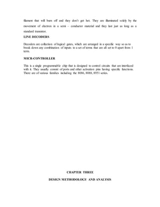
![smoothening out the unwanted ripple in the output. The capacitors basically store charges
temporarily and the stored charges are measured in farad, micro – farad and pico – farad.
The Regulator
A voltage regulator is an electrical regulator designed to automatically maintain a
constant voltage level. It may use an electromechanical mechanism, or passive or active
electronic component. Depending on the design, it may be used to regulate one or more
AC or DC voltages.
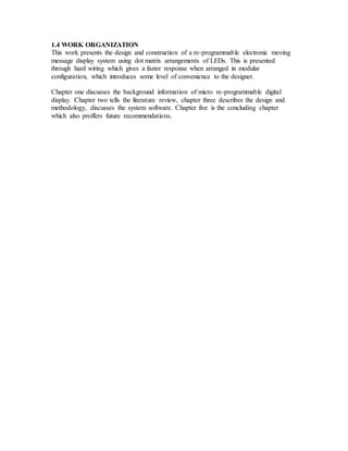
The voltage regulator used in this project is 78HC05 integrated circuit. It has three
terminals and is capable of supplying 5+ 10% at 100Ma
]
1 3
2
Circuit symbol of a voltage regulator with pin out indicator
Terminal 1 serves as the input. 2 serves as ground and 3 as the input terminal.
The 7805 used takes 12V from the transformer and gives output of 5V± 0.2%.
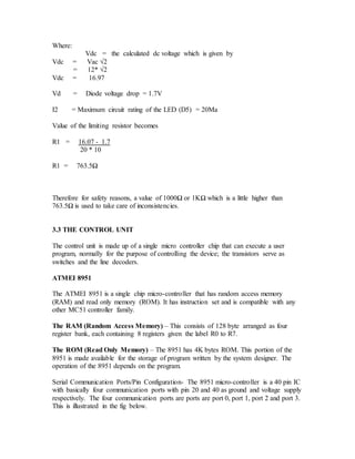
Power Indicator
Diode D5 is a light emitting diode used as power on indicator. This glows once power is
on. Resistor R1 is a circuit-limiting resistor, which helps to limit the amount of current
flowing through the diode D5.
The value of the limiting resistor is gotten by the expression.
Resistor R1 = (Vdc – Vd)
Imax
U 1
78105](https://image.slidesharecdn.com/2633fb0a-86d3-4ca8-9f44-37ee3d4e83ca-160811101415/85/ORIGINAL-PROJECT-13-320.jpg)
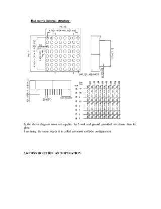
![Again, plasma display panels may be used in place of light emitting diodes to
accommodate certain areas of our economy that may require large display board for
advertisement.
There is significant need for future design to include a universal serial bus of a serial
interface that was used for the same purpose.
REFERENCES
B. Bahadur, Liquid Crystals: Applications and Uses. London: World Scientific, 1990
Coship. (n.d.) LED Basic Information. [Online]. Available:
www.coshipled.com/english/downloads/basic%20concepts.pdf August 8, 2008
[date accessed]](https://image.slidesharecdn.com/2633fb0a-86d3-4ca8-9f44-37ee3d4e83ca-160811101415/85/ORIGINAL-PROJECT-43-320.jpg)
![C. Kuhnel, BASCOM Programming of Microcontrollers with Ease. Berlin: Universal-
Publishers, 2001.
Focon Engineering. (n.d.) LED Colour Display Matrix Controller. [Online]. Available:
www.fuse-network.com/fuse/demonstration/34_35/22918/FL_22918.pdf August
8, 2008 [date accessed]
National Research Council (U.S.). Panel on Impact of Video Viewing on Vision of
Workers, Video Displays, Work and Vision. Washington: National Academies
Press, 1983. The Decoder. (n.d.). [Online]. Available: http://www.electronics-
tutorials.ws/combination/comb_5.html September 2, 2008 [date accessed]
R.K. Jurgen, Automotive Electronics Handbook. New York: McGraw-Hill Professional,
1999](https://image.slidesharecdn.com/2633fb0a-86d3-4ca8-9f44-37ee3d4e83ca-160811101415/85/ORIGINAL-PROJECT-44-320.jpg)
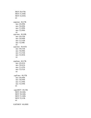
![Steven F. Barrett and Daniel J. Pack, Atmel AVR Microcontroller Primer: Programming and
Interfacing. London: Morgan & Claypool Publishers, 2007.
Viscomm Solutions. (n.d.). VS-4000 Next Generation LED Flexible Process Control Boards.
[Online]. Available: http://chris-hutchings.com/VS4000_LED_Display_Brochure.pdf
August 8, 2008 [date accessed]](https://image.slidesharecdn.com/2633fb0a-86d3-4ca8-9f44-37ee3d4e83ca-160811101415/85/ORIGINAL-PROJECT-45-320.jpg)