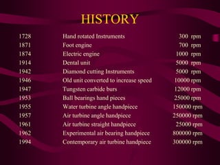
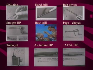
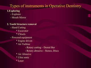
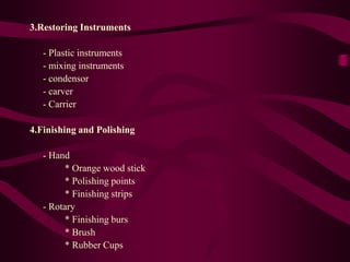
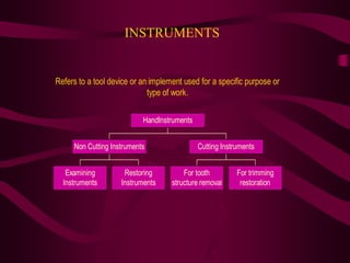
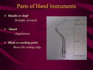
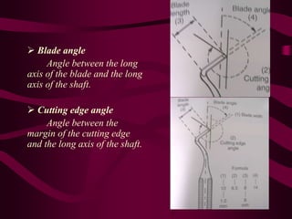
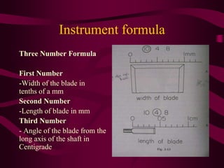
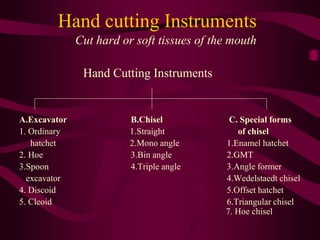
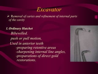
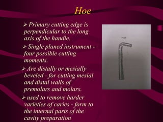
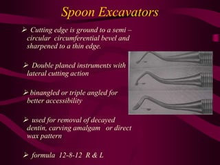
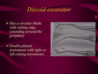
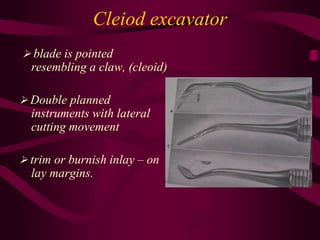
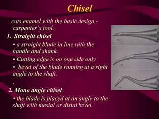
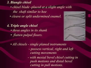
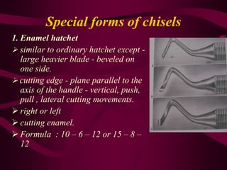
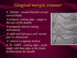
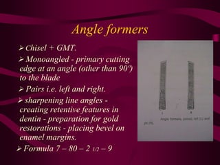
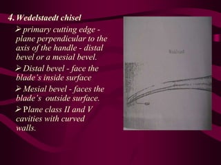
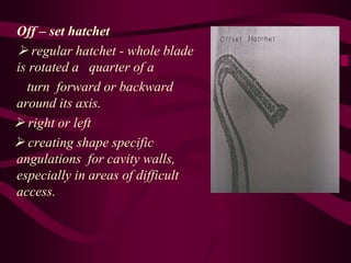
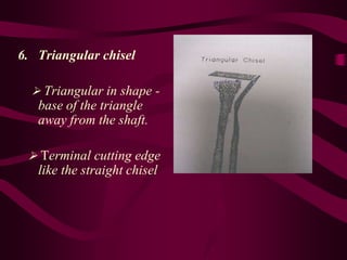
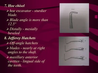
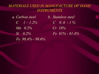
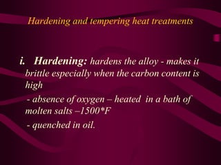
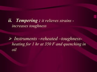
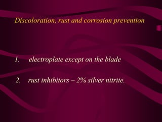
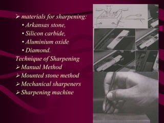
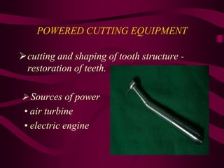
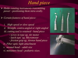
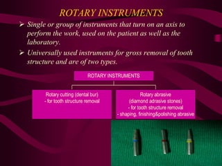
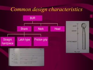
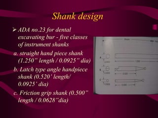
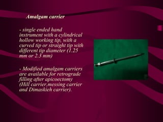
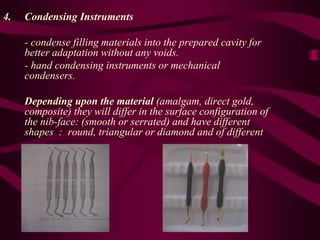
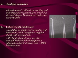
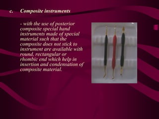
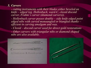
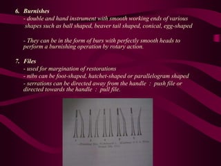
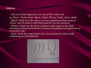
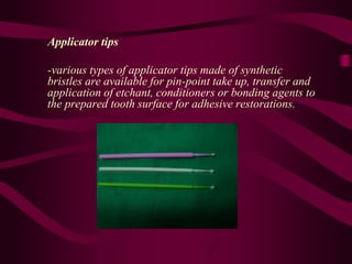
OPERATIVE
INSTRUMENTS
CONTENTS
* INTRODUCTION
* HISTORY
* CLASSIFICATION
* INSTRUMENTS FOR TOOTH STRUCTURE
REMOVAL
* INSTRUMENTS FOR FINISHING AND
POLISHING
* STERILIZATION OF INSTRUMENTS
Introduction
The armamentarium of operative dentistry
has grown tremendously over the years
resulting in a highly successful and
predictable outcome.
HISTORY
1728 Hand rotated Instruments 300 rpm
1871 Foot engine 700 rpm
1874 Electric engine 1000 rpm
1914 Dental unit 5000 rpm
1942 Diamond cutting Instruments 5000 rpm
1946 Old unit converted to increase speed 10000 rpm
1947 Tungsten carbide burs 12000 rpm
1953 Ball bearings hand pieces 25000 rpm
1955 Water turbine angle handpiece 150000 rpm
1957 Air turbine angle handpiece 250000 rpm
1961 Air turbine straight handpiece 25000 rpm
1962 Experimental air bearing handpiece 800000 rpm
1994 Contemporary air turbine handpiece 300000 rpm
Drill ring Hand drill Belt driven
Straight HP Bow drill Page – chayes
Turbo jet Air turbine HP AT St. HP
“The Workman is known by his tools”
Types of instruments in Operative Dentistry
1.Exploring
- Explorer
- Mouth Mirror
2. Tooth Structure removal
- Hand Cutting
* Excavator
* Chisels
- Powered equipment
* Engine driven
* Air Turbine
- Rotary cutting – Dental Bur
- Rotary abrasive – Stones, Discs
* Air Abrasive
* Ultra sonic
* Laser
3.Restoring Instruments
- Plastic instruments
- mixing instruments
- condensor
- carver
- Carrier
4.Finishing and Polishing
- Hand
* Orange wood stick
* Polishing points
* Finishing strips
- Rotary
* Finishing burs
* Brush
* Rubber Cups
INSTRUMENTS
Refers to a tool device or an implement used for a specific purpose or
type of work.
Examining
Instruments
Restoring
Instruments
Non Cutting Instruments
For tooth
structure removal
For trimming
restoration
Cutting Instruments
HandInstruments
Parts of Hand instruments
 Handle or shaft
Straight, serrated
 Shank
Angulations
 Blade or working point
Bears the cutting edge.
 Blade angle
Angle between the long
axis of the blade and the long
axis of the shaft.
 Cutting edge angle
Angle between the
margin of the cutting edge
and the long axis of the shaft.
Instruments Nomenclature
In 1908, G.V.Black
Order : Purpose of Instrument
Eg : Excavator, Scaler
Sub order : Position or manner of use
Eg : Push, Pull
Class : Form of working end
Eg : Hatchet, Chisel
Sub class : Shape of shank and number of angles
in the shank
Eg : Mono angle, Biangle, Triple
angle
Instrument formula
Three Number Formula
First Number
-Width of the blade in
tenths of a mm
Second Number
-Length of blade in mm
Third Number
- Angle of the blade from the
long axis of the shaft in
Centigrade
Four Number formula
First Number
- Width of the blade in tenths of a mm
Second Number
- Angle of the cutting edge from the long axis of the
shaft in centigrade
Third Number
- Length of blade in mm
Fourth Number
- Angle of the blade from the long axis of the shaft in
Centigrade
Specific designs for hand cutting instruments
 The main principle of cutting
with hand instruments is to
concentrate forces on a very
thin cross section the
instrument, at the cutting
edge.
 Thinner the cross section -
more the pressure is
concentrated - more efficient
is the instrument.
Direct cutting instrument
- force is applied in the same plane
as that of the blade and handle and
is called a “single planed”
instrument.
- non-beveled side of the blade should
be in contact with the wall being
shaved.
Lateral cutting instrument
- force is applied at a right angle to
the plane of the blade and handle
and is called a “double planed”
instrument with a curved blade.
- move the instrument in a scraping
motion from the beveled side to the
non-beveled side of the blade.
Right and left side instruments
- the primary cutting edge is
held down and pointing away – if
the bevel appears on the right side
of the blade, it is the right side
instrument of the pair and vice
versa for left side instrument.
- ring on the shank identifies
the right of the pair or the letter
‘L’ or ‘R’ is added to the
instrument formula.
Single Bevelled Instruments
single planed with cutting edge at a
right angle to the long axis of the shaft.
Bibevelled Instruments
The blade is equally beveled on both
sides; they cut by pushing them in the
direction of the long axis of the blade.
Triple beveled Instruments
Beveling the blade laterally, together
with the end, forms three distinct cutting
edges, which afford an additional cutting
potential.
Circumferentially Bevelled Instruments
It is done in double planed instruments
where the blade is beveled at all
peripheries.
 Contra angling
- Instruments with longer
blades or more complex
orientations may require two or
three angles in the shank to bring
the cutting edge near to the long
axis of the handle such shanks are
termed contra angle instruments.
- The advantages will be of
providing better access and
clearer view of the field.
 Double ended Instruments
- Blades and shanks on both
ends of the handle.
- The right instrument of the
pair is on one end of the handle
and the left is on the other end.
Instruments Measuring Gauge
PRINCIPLE OF BALANCE
 Balance is accomplished by designing the angles of the
shank so that the cutting edge of the blade lies within the
projected diameter of the handle and nearly coincides with
the projected axis of the handle.
 For optical anti rotational design the blade edge must not
be off the axis by more than 1-2 mm.
Non – cutting Hand Instruments
 Exploring Instruments
- Explorers
- Mouth mirrors
- Tissue Retractors
Explorers
 Straight explorer
 Right angled explorer
 Arch explorer
 Briault’s probe or interproximal
explorer
Uses
- Determine the mobility of the tooth and
periodontal pockets.
- Evaluate the depth and smoothness of
cavity preparations
- Diagnose secondary caries between
restoration and tooth interface
- Remove excess cement after luting
procedure.
Tweezers
- help in placing cotton for isolation
Tongue and cheek retractors
Mouth mirror
 It has a handle with
detachable mirror part.
retraction,illumination,visualiza
tion.
 Sizes of ¾” to 1 ½” in
diameter.
Plain glass Magnifying
Glass
Anti fog Light
attatched
Parallelometer
mirror
Mouth Mirror
Hand cutting Instruments
Cut hard or soft tissues of the mouth
Hand Cutting Instruments
A.Excavator B.Chisel C. Special forms
1. Ordinary 1.Straight of chisel
hatchet 2.Mono angle 1.Enamel hatchet
2. Hoe 3.Bin angle 2.GMT
3.Spoon 4.Triple angle 3.Angle former
excavator 4.Wedelstaedt chisel
4. Discoid 5.Offset hatchet
5. Cleoid 6.Triangular chisel
7. Hoe chisel
Excavator
 Removal of caries and refinement of internal parts
of the cavity
1.Ordinary Hatchet
Bibevelled.
push or pull motion,
Used in anterior teeth
-preparing retentive areas
-sharpening internal line angles,
-preparations of direct gold
restorations.
Hoe
 Primary cutting edge is
perpendicular to the long
axis of the handle.
 Single planed instrument -
four possible cutting
moments.
 Are distally or mesially
beveled - for cutting mesial
and distal walls of
premolars and molars.
 used to remove harder
varieties of caries - form to
the internal parts of the
cavity preparation
Spoon Excavators
 Cutting edge is ground to a semi –
circular circumferential bevel and
sharpened to a thin edge.
 Double planed instruments with
lateral cutting action
 binangled or triple angled for
better accessibility
 used for removal of decayed
dentin, carving amalgam or direct
wax pattern
 formula 12-8-12 R & L
Discoid excavator
 Has a circular blade,
with cutting edge
extending around the
periphery
 Double planed
instrument with right or
left cutting movements.
Cleiod excavator
 blade is pointed
resembling a claw, (cleoid)
 Double planned
instruments with lateral
cutting movement
 trim or burnish inlay – on
lay margins.
Chisel
cuts enamel with the basic design -
carpenter’s tool.
1. Straight chisel
• a straight blade in line with the
handle and shank.
• Cutting edge is on one side only
• bevel of the blade running at a right
angle to the shaft.
.
2. Mono angle chisel
• the blade is placed at an angle to the
shaft with mesial or distal bevel.
3. Biangle chisel
• chisel blade -placed at a slight angle with
the shaft similar to hoe
• cleave or split undermined enamel.
4. Triple angle chisel
• three angles in its shank
• flatten pulpal floors.
• All chisels - single planed instruments
- possess vertical, right and left
cutting movements
- with mesial bevel chisel cutting in
push motions and distal bevel
cutting in pull motions.
Special forms of chisels
1. Enamel hatchet
 similar to ordinary hatchet except -
large heavier blade - beveled on
one side.
 cutting edge - plane parallel to the
axis of the handle - vertical, push,
pull , lateral cutting movements.
 right or left
 cutting enamel.
 Formula : 10 – 6 – 12 or 15 – 8 –
12
Gingival margin trimmer
 Similar - enamel hatchet except -
curved blade.
 primary cutting edge - angle to
the axis of the handle
 primarily lateral cutting
instruments.
 right and left types and mesial
pair or distal pair.
 lateral scrapping motion
 D – GMT - cutting edge - acute
angle with that edge of the blade
furthest from the handle
 M – GMT cutting edge acute angle with that edge of the
blade nearer to the handle
 rounding or beveling - axiopulpal line angle of two surface
preparations - placement of gingival lock in decline.
 D - GMT 10 – 92 – 6 –12
 M - GMT 10 – 80 – 6 – 12
 100/75 – inlay, onlay preparation
Angle formers
 Chisel + GMT.
 Monoangled - primary cutting
edge at an angle (other than 90º)
to the blade
 Pairs i.e. left and right.
 sharpening line angles -
creating retentive features in
dentin - preparation for gold
restorations - placing bevel on
enamel margins.
 Formula 7 – 80 – 2 1/2 – 9
4.Wedelstaedt chisel
 primary cutting edge -
plane perpendicular to the
axis of the handle - distal
bevel or a mesial bevel.
 Distal bevel - face the
blade’s inside surface
 Mesial bevel - faces the
blade’s outside surface.
 Plane class II and V
cavities with curved
walls.
Off – set hatchet
 regular hatchet - whole blade
is rotated a quarter of a
turn forward or backward
around its axis.
 right or left
 creating shape specific
angulations for cavity walls,
especially in areas of difficult
access.
6. Triangular chisel
 Triangular in shape -
base of the triangle
away from the shaft.
 Terminal cutting edge
like the straight chisel
7. Hoe chisel
 hoe excavator - sturdier
blade.
 Blade angle is more than
12.5º
 Distally - mesially
beveled
8. Jefferey Hatchets
 Off-angle hatchets
 blades - nearly at right
angles to the shaft.
 maxillary anterior
cavities - lingual side of
the teeth.
MATERIALS USED IN MANUFACTURE OF HAND
INSTRUMENTS
a. Carbon steel b. Stainless steel
C 1 – 1.2% C 0 .6 - 1 %
Mn 0.2% Cr 18%
Si 0.2% Fe 81% - 81.4%
Fe 98.4% - 98.6%
Hardening and tempering heat treatments
i. Hardening: hardens the alloy - makes it
brittle especially when the carbon content is
high
- absence of oxygen – heated in a bath of
molten salts –1500*F
- quenched in oil.
ii. Tempering : it relieves strains -
increases toughness
 Instruments –reheated –toughness-
heating for 1 hr at 350 F and quenching in
oil
Discoloration, rust and corrosion prevention
1. electroplate except on the blade
2. rust inhibitors – 2% silver nitrite.
GRASPS
 essential for performing operative dental
procedure
 control of the instrument while allowing
flexibility of motion & précised adaptation
 prevention of muscle fatigue -fingers, hand
,arm
 allows controlled application -pressure to
the instruments.
Types of grasps.
 Modified pen grasp
Inverted pen grasp Palm and thumb grasp Modified palm and thumb grasp
SHARPENING OF HAND INSTRUMENTS
 Repeated use & sterilization renders instrument
dull
 Moreover dull instrument
- reduces quality of work done & affects precision
- Prolongs operating time
- necessitates use of excessive pressure
- Increases risk of trauma to the surrounding soft
tissues
- contributes operator’s fatigue at an early stage.
 materials for sharpening:
• Arkansas stone,
• Silicon carbide,
• Aluminium oxide
• Diamond.
Technique of Sharpening
 Manual Method
 Mounted stone method
 Mechanical sharpeners
 Sharpening machine
POWERED CUTTING EQUIPMENT
cutting and shaping of tooth structure -
restoration of teeth.
 Sources of power
• air turbine
• electric engine
Hand piece
 Holds rotating instruments transmitting
power - positioning them intra orally.
 Certain features of hand piece:
i. High speed or slow speed
ii Straight, contra-angled or right angled
iii. cutting tool is retained - hand piece
- screw in type eg. Air motor
- latch type eg. Micromotor -
- friction grip eg. Airotor hand piece
iv. Fiber optic light attachment
v. normal head – adult size
vi. miniature head - pediatric sizes.
Criteria used in evaluating hand pieces:
a. Friction – occur in turbine, hence heat generated -
prevented or counter acted with bearings(ball
bearings, glass resin bearings).
b. Torque – Is the ability of hand piece to withstand lateral
pressure on the revolving tool without decreasing
speed and cutting efficiency.
- Depends on the bearing and energy supplied.
c. Vibration – deleterious, and leads to wear of the turbine
bearings.
Speed
Rotational speed is measured in revolution per
minute
Classification – Marzouk
1. Ultra low speed ( 300 – 3000 rpm)
2. Low speed (3000 – 6000 rpm)
3. Medium high speed (20,000 – 45,000 rpm)
4. High speed (45,000 – 1,00,000 rpm)
5. Ultra high speed (1,00,000 rpm & more)
Classification – Sturdevant
1. Low or slow speed ( below 12,000 rpm)
2. Medium or intermediate speed ( 12,000 –
2,00,000 rpm)
3. High or Ultra high speeds ( above
2,00,000 rpm)
High speed hand piece < Airotor hand piece>
Working mechanism
 is driven by compressed air
 the head contains a catridge
which contain the air turbine
with a central chunk.
 The turbine is held in position
by two sets of ball bearings on
the upper and lower ends. When
air pressure turns the turbine,
the central chunk also rotates
along with it. Bearings ensure
that while the turbine rotates,
the catridge doesn,t.
Slow Speed handpiece ( Air motor or
micromotor )
working mechanism
 either an air driven motor(air motor) or
a electrically driven miniature motor (
micro motor) can bee used for driving the
hand piece.
 the motor turn the central shaft which
will be coupled to the drive spindle of the
handpiece.
 In a straight handpiece, the drive spindle
ends in a collets chunk for receiving the
bur.
 In a contra angle handpiece, a crown
wheel gear box is provided between two
drive shafts which placed in the head, is
attached to drive pinion which has the bur
tube for placing the bur. The two bearings(
upper and lower) hold the bur tube and
pinion in place. Latch type (ratchet)
attachment holds the bur.
ROTARY INSTRUMENTS
 Single or group of instruments that turn on an axis to
perform the work, used on the patient as well as the
laboratory.
 Universally used instruments for gross removal of tooth
structure and are of two types.
Rotary cutting (dental bur)
- for tooth structure removal
Rotary abrasive
(diamond adrasive stones)
- for tooth structure removal
- shaping, finishing&polishing abrasive
ROTARY INSTRUMENTS
Characteristics of rotary instrumentation
a. Speed refers to the surface feet per unit time of
contact that the tool has the work to be cut and is
indicated in rpm.
b. Pressure (P) is a resultant effect of two factors
under the control of the operator i.e. P = F/A.
C. Force(F) gripping of the handpiece and its
positioning and application to the tooth.
d. Area (A) amount of surface area of the cutting
tool in contact with the tooth surface during a
cutting procedure.
 Heat production is directly proportional to P, rpm
and area of tooth in contact with the tool.
 Vibration:- annoying factor for the patient
- fatigue for operator
- excessive wear of instruments
- destructive reaction in the tools and
supporting tissues
 Ideal requirements for better cutting efficiency
- greater rpm
- smaller cutting tool
- less force
- effective lubrication
Common design characteristics
Straight
handpiece
Latch type Friction grip
Shank Neck Head
BUR
Shank design
 ADA no.23 for dental
excavating bur - five classes
of instrument shanks
a. straight hand piece shank
(1.250” length / 0.0925” dia)
b. Latch type angle handpiece
shank (0.520’ length/
0.0925’ dia)
c. Friction grip shank (0.500”
length / 0.0628”dia)
Neck design
 It normally tapers from the shank
diameter to a smaller size immediately
adjacent to the head.
 It transmits rotational and transitional
force to the head.
Head design
Classification :
a. Type : bladed or abrasive instrument.
b. Material : tungsten carbide, steel or
diamond abrasives
c. Head size : regular or long
d. Head shape : round, straight, tapering
DENTAL BURS
 Bur is applied to all rotary cutting instruments
that have bladed cutting heads.
i. Steel burs
 Cut from blank steel stock by rotary cutter that
cuts parallel to the long axis of the bur.
 Hardened and tempered – VHN 800.
 Cuts human dentin at low speeds,
 Dull rapidly at higher speeds - cutting enamel.
 Finishing procedures.
Tungsten carbide burs
product of powder metallurgy
tungsten carbide powder + powdered cobalt
under pressure and heated in a vacuum.
A partial alloying or sintering of the metals
take place. A blank is then formed and the
bur is cut from it with a diamond tool.
VHN 1650 – 1700.
General design of dental burs ( blade design )
Dental Bur : is a small cutting instruments.
. Bur tooth : terminates in the cutting edge or
blade
two surfaces -tooth face, back or
flank of the tooth
Rake angle : is the angle that the face
of the bur tooth makes with the
radial line from the center of the
bur to the blade
Referring to the direction of rotation,
the angle can be.
Negative : if the face is beyond or
leading the radial line
Zero : if the radial line and the
tooth face coincide
with each other i.e.
radial rake angle
Positive : if the radial line leads the
face i.e. the rake angle is
Inside the radial line
Land : the plane surface immediately following the
cutting edge.
Clearance angle : the angle
between the back of the tooth
and the work
if a land is present on the bur, the
clearance angle is divided into
primary clearance : the angle
the land will make with work.
Secondary clearance : the angle
between the back of the bur tooth
and the work
Radial clearance: back surface
of the tooth is curved
Tooth angle : this is measured
between the face
and the back.
- If a land is present, it is
measured between face
and land.
Flute or chip space : the space
between successive teeth.
Factors influencing the cutting efficiency of burs
i.Rake angle
 negative rake angle is ideal
ii. clearance angle
 large clearance angle will help in less rapid dulling of the bur.
iii.Number of tooth or blades and their distribution
 excavating bur may vary from 6 to 8 to 10.
 finishing bur - 12 – 40 blades.
iv. Run out and concentricity
 concentricity is a direct
measurement of the symmetry of the
bur head.
It indicates whether one blade is
longer or shorter than the others
and is a static measurement.
 Run out is a dynamic test
measuring the accuracy with which
all blade tips pass through a single
point when the instrument rotates.
It measures the concentricity and
also the accuracy with which the
center of rotation passes through
the center of the head.
 Even a perfectly concentric head will exhibit substantial
run out if :
- the head is off center on the axis of the bur
- the bur neck is bent
- the bur is not held straight in the handpiece chuck
- the chuck is eccentric relative to the hand piece
bearings
 0.023 mm
V. Finish of the flutes
Tests for cutting efficiency were done on different types of bur undergoing two,
four and six flute cuts.
Those cut six times were the most efficient while those cut two times were the
least efficient.
vi. Heat treatment
Hardens the bur to increase cutting life.
vii. Design of the flute ends
Dental burs are formed with two different styles of end flutes:
a. the revelation cut, where the flutes came together at two junction near a
diametrical cutting edge.
b. the star cut, where the end flutes come together in a common junction at
the axis of the bur.
The revelation type shows superiority in cutting efficiency during direct
cutting but in lateral cutting both are equal.
viii. Bur diameter
 With the length of cut as a constant the volume of material removed
will vary directly with the bur diameter.
ix. Depth of engagement
 Volume of material removed by a shallow cut exceeds that of
deeper cuts because as the depth of engagement is decreased, the
force intensity on each small portion of the bur tooth cutting is
correspondingly increased.
Influence of load
 Load signifies the force exerted by the dentists on the
tool head and is related to the rotational speed of the bur
of a given design the minimum and maximum loads for:
- low speed 1000 – 1500 gm
- high speed 60 – 120 gm
Bur classification systems
S.S .White Dental Manufacturing company in 1891 :
Original numbering system grouped burs by 9 shapes and 11 sizes.
½ and ¼ designations were added - smaller instruments
original - continuous blade edges.
cross cut modification - adding 500 to the number of the equivalent non cross
cut size.( eg . No.57 with crosscut was designated No. 557). Similarly a 900
premix was used to indicate a head design intended for end cutting only.
Except for differences in blade design eg a No.957, No. 557 and no. 57 bur all
had the same head dimensions.
In united states dental burs
An arbitrary numerical code for head size and shape. Eg.
2 = 1.00 mm dia round bur,
34 = 0.8mm dia inverted cone bur.
Despite the complexity of the system. It is still in common
use.
International dental federation (FDI) and International
Standards organization (ISO)
Number giving the head diameter in tenths of a mm.
Eg. Round 010, inverted cone 008.
Abrasive Instruments
Tooth cutting abrasive Shaping, finishing
Polishing abrasives
Dental abrasives – Natural or Synthetic
Diamond Carbide Aluminum oxide Garnet Cuttle bone Sand
i. Diamond Abrasive instruments ( US 1942 )
hardest and most efficient abrasive stone for removing
tooth enamel.
The instruments are of various types:
Mounted.
Unmounted.
Strips.
Clinical performance of diamond abrasive
instruments depends on particle
a. Size
Grit Particle size Colour code
Coarse
Medium
125 – 150 μm
83 – 125 μm
Green
Blue
Gross removal
Fine
Very fine
60 – 74 μm
38 – 44 μm
Red
Yellow
Finishing and
smoothing
b. Spacing : Less spacing increases the diamond particles
for more contact with the abrading surface.
c. Uniformity
d. Exposure
e. Bonding
ULTRASONIC INSTRUMENTS
-ultrasonic generator +magnetostructive
transducer located within the handpiece.
- The generator delivers the energy to
the transducer which in turn creates vibrations
used it remove hard substances.
- direct a water borne abrasive or slurry
against the working point while providing an
additional jet for irrigation.
- Energy used for removal of enamel and dentin is generated within the
handpioece.
- Electric current causes the transducer of the handpiece to slightly
contract and expand.
- The amplitudes of this movement is determined by the number of
watts delivered to the handpiece and may be variable.
- The desirable amplitude depends on the length and thickness of the
working point and is under the control of the operator.
- Working points used for removal of enamel and dentin are
constructed to tolerate greater amplitudes.
- Generally speaking, ultrasonic are not universally used for cavity
preparations.
AIR ABRASIVE CUTTING EQUIPMENT
rely on transfer of kinetic energy-stream of powder
particles on tooth –roughness.
It has certain clinical problem
- the abrasive dust interfered with visibility of the site
- lack of tactile sensation
- abrasive dust inhalation
- mechanically etched the surface of the dental mirror
Hence conventional cavity preparation was not
possible.
At present air abrasive equipment ( KCP 2000) is
being used for
-stain removal
- debriding pit and fissures
- micro mechanical roughening of surfaces to be
bonded.
LASER EQUIPMENT
The lasers which are of current
interest to conservative dentistry
are:
Na : YAG, (1.064 μm)
Er : YAG & CO2 (10.6 μm)
(2.94 μm)
Er : YAG laser ablated carious
dentin effectively with minimal
thermal damage to the surrounding
intact dentin and removed infected
and softened carious dentin to the
same degree as the Bur treatment.
Ho: YAG laser instruments – Food
and drug administration – hard
tissues – primary teeth
INSTRUMENTS FOR RESTORING
PROCEDURES
variety or a combination of restoring instruments.
may be either a hand, rotary or mechanical
instrument.
1. Mixing Instruments
- spatula (hand instrument)
- they have flat and wide nibs with blunt edges and
straight shank
- double ended instrument with other end sharp.
- Are of different sizes with different degrees of
stiffness in their Niles to suit various sizes.
- made of stainless steel or plastic.
2. Plastic instruments
- May be made of stainless steel, or plastic and also plated with Teflon
or anodized aluminum titanium nitride coated to minimize material
adhesion (composite manipulation) and facilitate easy cleaning
Amalgam carrier
- single ended hand
instrument with a cylindrical
hollow working tip, with a
curved tip or straight tip with
different tip diameter (1.25
mm or 2.3 mm)
- Modified amalgam carriers
are available for retrograde
filling after apicoectomy
(Hill carrier,messing carrier
and Dimaskieh carrier).
4. Condensing Instruments
- condense filling materials into the prepared cavity for
better adaptation without any voids.
- hand condensing instruments or mechanical
condensers.
Depending upon the material (amalgam, direct gold,
composite) they will differ in the surface configuration of
the nib-face: (smooth or serrated) and have different
shapes : round, triangular or diamond and of different
a. Amalgam condenser
- double ended, cylindrical working end
with smooth or serrated face of various
size and shapes Mechanical condensers
are available.
b. Cohesive gold condensers
- available as single end or double end
instrument, with straight or angular
shank with serrated nib.
- Mechanical condenser are also
available wherein the handpiece is
adjusted so that it delivers 360 – 3600
blows/minute.
c. Composite instruments
- with the use of posterior
composite special hand
instruments made of special
material such that the
composite does not stick to
instrument are available with
round, rectangular or
rhombic end which help in
insertion and condensation of
composite material.
5. Carvers
- cutting instruments with their blades either beveled on
knife – edged (eg. Hollenback, ward-C, cleoid discoid
carver, Frahm’s carver (diamond carvers)).
- Hollenback carver posses double – side knife edged point
edged nibs with curved monoangled or biangled shanks –
efficient in carving amalgam and wax.
- Cleoid – discoid carver used for direct gold restorations
- Other carvers with triangular nibs or diamond shaped
nibs are also available.
6. Burnishes
- double and hand instrument with smooth working ends of various
shapes such as ball shaped, beaver tail shaped, conical, egg-shaped
- They can be in the form of burs with perfectly smooth heads to
perform a burnishing operation by rotary action.
7. Files
- used for margination of restorations
- nibs can be foot-shaped, hatchet-shaped or parallelogram shaped
- serrations can be directed away from the handle : push file or
directed towards the handle : pull file.
9.Knives
- nibs cary knife edges faces on one of their sides only
eg. Bard – Parker knife, Black’s knife, Wilson’s knife, stein’s knife.
- Black’s knife have the nibs at various angulations from acute to
obtuse, may be push or pull knife used for various purposes
- Wilson’s knife has the nib in a plane a right angle to the shaft,
introduced interproximally for proximal and gingival manipulation of
restorative tips.
- Stein’s knife has trapezoidal nib is used mainly for direct gold
contouring and margination.
Applicator tips
-various types of applicator tips made of synthetic
bristles are available for pin-point take up, transfer and
application of etchant, conditioners or bonding agents to
the prepared tooth surface for adhesive restorations.
Finishing and Polishing
Instruments
a. Molded abrasives
-heads are manufactured by molding or pressing a uniform
mixture of abrasive and matrix ( phenolic resins)around the
roughened end of the shank or cementing a pre-molded head to
the shank
-molded points are sintered or resin-bonded
-unmounted discs are attached to a handpiece through a mandrel
- reshaping of stones or points is done by placing a shaping stone
against the rotating instruments.
b. Coated Abrasive
-thin layer of abrasive cemented to a flexible backing(rubber
matrix)
-allows to conform to the surface contour of tooth or restoration
snap type mandrel attachments types.
-Softer less water resistant hence lose cutting efficiency with use
and hence discarded.
-Available in various grits: coarse ( 74 m), medium (37m),
fine (13m) and extra fine (3 m).
c. Different types of abrasives and uses
i. Silicon carbide
ii. Aluminium Oxide.
iii. Sandpaper disks (Garnet and Cuttle fish)
iv.Crocus disks
2 .Finishing Burs
3. Paper strip abrasives
4. Brushes
5. Rubber
6. Cloth
7. Flet
d. MANDRELS
STERILIZATION OF INSTRUMENTS
A. CLEANING
- The safest and most efficient instrument cleaning
procedure is by ultrasonic cleaning of used instruments
kept in a perforated basket or cassette. The cleanser is run
for about a minimum period of 5 minutes.
B. STERILIZATION
1. Steam pressure sterilization
2. Chemical vapour pressure sterilization
3. Dry heat sterilization
4. Ethylene oxide sterilization
Steam pressure sterilization
- Moist heat denatures and coagulates the protein of a micro organism
121C - 20 min. - 15 lb pressure.
- All stainless steel instruments, most hand pieces, burs can be
autoclaved
Chemical vapour pressure sterilization
Chemiclave-131C and 20 lbs pressure - 30 minutes
and use aldehyde vapours.
Carbon steel and other corrosion sensitive burs and
instruments and “lube free” ceramic bearing turbine hand
pieces can be chemiclaved.
Dry heat sterilization
At 160C and 90 min. Stainless steel, carbon steel
instruments and burs can be sterilized by this method.
Ethylene oxide sterilization
- Micromotor cord and airtor cord can be sterilized by using this
gas sterilization.
- Hand pieces can be sterilized overnight by ETOX method.
ASSISTAN - Sterilizes and lubricates the airotor hand piece at a
short span of 30 seconds. Fixed in a closed chamber and operated
through electricity. It is very ideal to use in between patients
The fibre optics in the hand piece are wiped with alcohol or other
organic solvents to increase its longevity.
Ultraviolet Radiation
- Microbicidal effect on the pyramidine
dimers within the DNA strands.
- Bactericidal range of UV rays is between
2400-2800 A*
Newer Instruments
Conclusion:
The judicious usage of hand cutting
instruments along with mechanical
instruments is the key for a successful
conservative treatment.

Operative Instruments

  • 1.
  • 2.
    CONTENTS * INTRODUCTION * HISTORY *CLASSIFICATION * INSTRUMENTS FOR TOOTH STRUCTURE REMOVAL * INSTRUMENTS FOR FINISHING AND POLISHING * STERILIZATION OF INSTRUMENTS
  • 3.
    Introduction The armamentarium ofoperative dentistry has grown tremendously over the years resulting in a highly successful and predictable outcome.
  • 4.
    HISTORY 1728 Hand rotatedInstruments 300 rpm 1871 Foot engine 700 rpm 1874 Electric engine 1000 rpm 1914 Dental unit 5000 rpm 1942 Diamond cutting Instruments 5000 rpm 1946 Old unit converted to increase speed 10000 rpm 1947 Tungsten carbide burs 12000 rpm 1953 Ball bearings hand pieces 25000 rpm 1955 Water turbine angle handpiece 150000 rpm 1957 Air turbine angle handpiece 250000 rpm 1961 Air turbine straight handpiece 25000 rpm 1962 Experimental air bearing handpiece 800000 rpm 1994 Contemporary air turbine handpiece 300000 rpm
  • 5.
    Drill ring Handdrill Belt driven Straight HP Bow drill Page – chayes Turbo jet Air turbine HP AT St. HP
  • 6.
    “The Workman isknown by his tools”
  • 7.
    Types of instrumentsin Operative Dentistry 1.Exploring - Explorer - Mouth Mirror 2. Tooth Structure removal - Hand Cutting * Excavator * Chisels - Powered equipment * Engine driven * Air Turbine - Rotary cutting – Dental Bur - Rotary abrasive – Stones, Discs * Air Abrasive * Ultra sonic * Laser
  • 8.
    3.Restoring Instruments - Plasticinstruments - mixing instruments - condensor - carver - Carrier 4.Finishing and Polishing - Hand * Orange wood stick * Polishing points * Finishing strips - Rotary * Finishing burs * Brush * Rubber Cups
  • 9.
    INSTRUMENTS Refers to atool device or an implement used for a specific purpose or type of work. Examining Instruments Restoring Instruments Non Cutting Instruments For tooth structure removal For trimming restoration Cutting Instruments HandInstruments
  • 10.
    Parts of Handinstruments  Handle or shaft Straight, serrated  Shank Angulations  Blade or working point Bears the cutting edge.
  • 11.
     Blade angle Anglebetween the long axis of the blade and the long axis of the shaft.  Cutting edge angle Angle between the margin of the cutting edge and the long axis of the shaft.
  • 12.
    Instruments Nomenclature In 1908,G.V.Black Order : Purpose of Instrument Eg : Excavator, Scaler Sub order : Position or manner of use Eg : Push, Pull Class : Form of working end Eg : Hatchet, Chisel Sub class : Shape of shank and number of angles in the shank Eg : Mono angle, Biangle, Triple angle
  • 13.
    Instrument formula Three NumberFormula First Number -Width of the blade in tenths of a mm Second Number -Length of blade in mm Third Number - Angle of the blade from the long axis of the shaft in Centigrade
  • 14.
    Four Number formula FirstNumber - Width of the blade in tenths of a mm Second Number - Angle of the cutting edge from the long axis of the shaft in centigrade Third Number - Length of blade in mm Fourth Number - Angle of the blade from the long axis of the shaft in Centigrade
  • 15.
    Specific designs forhand cutting instruments  The main principle of cutting with hand instruments is to concentrate forces on a very thin cross section the instrument, at the cutting edge.  Thinner the cross section - more the pressure is concentrated - more efficient is the instrument.
  • 16.
    Direct cutting instrument -force is applied in the same plane as that of the blade and handle and is called a “single planed” instrument. - non-beveled side of the blade should be in contact with the wall being shaved. Lateral cutting instrument - force is applied at a right angle to the plane of the blade and handle and is called a “double planed” instrument with a curved blade. - move the instrument in a scraping motion from the beveled side to the non-beveled side of the blade.
  • 17.
    Right and leftside instruments - the primary cutting edge is held down and pointing away – if the bevel appears on the right side of the blade, it is the right side instrument of the pair and vice versa for left side instrument. - ring on the shank identifies the right of the pair or the letter ‘L’ or ‘R’ is added to the instrument formula.
  • 18.
    Single Bevelled Instruments singleplaned with cutting edge at a right angle to the long axis of the shaft. Bibevelled Instruments The blade is equally beveled on both sides; they cut by pushing them in the direction of the long axis of the blade. Triple beveled Instruments Beveling the blade laterally, together with the end, forms three distinct cutting edges, which afford an additional cutting potential. Circumferentially Bevelled Instruments It is done in double planed instruments where the blade is beveled at all peripheries.
  • 19.
     Contra angling -Instruments with longer blades or more complex orientations may require two or three angles in the shank to bring the cutting edge near to the long axis of the handle such shanks are termed contra angle instruments. - The advantages will be of providing better access and clearer view of the field.  Double ended Instruments - Blades and shanks on both ends of the handle. - The right instrument of the pair is on one end of the handle and the left is on the other end.
  • 20.
  • 21.
    PRINCIPLE OF BALANCE Balance is accomplished by designing the angles of the shank so that the cutting edge of the blade lies within the projected diameter of the handle and nearly coincides with the projected axis of the handle.  For optical anti rotational design the blade edge must not be off the axis by more than 1-2 mm.
  • 22.
    Non – cuttingHand Instruments  Exploring Instruments - Explorers - Mouth mirrors - Tissue Retractors
  • 23.
    Explorers  Straight explorer Right angled explorer  Arch explorer  Briault’s probe or interproximal explorer Uses - Determine the mobility of the tooth and periodontal pockets. - Evaluate the depth and smoothness of cavity preparations - Diagnose secondary caries between restoration and tooth interface - Remove excess cement after luting procedure.
  • 24.
    Tweezers - help inplacing cotton for isolation Tongue and cheek retractors
  • 25.
    Mouth mirror  Ithas a handle with detachable mirror part. retraction,illumination,visualiza tion.  Sizes of ¾” to 1 ½” in diameter. Plain glass Magnifying Glass Anti fog Light attatched Parallelometer mirror Mouth Mirror
  • 26.
    Hand cutting Instruments Cuthard or soft tissues of the mouth Hand Cutting Instruments A.Excavator B.Chisel C. Special forms 1. Ordinary 1.Straight of chisel hatchet 2.Mono angle 1.Enamel hatchet 2. Hoe 3.Bin angle 2.GMT 3.Spoon 4.Triple angle 3.Angle former excavator 4.Wedelstaedt chisel 4. Discoid 5.Offset hatchet 5. Cleoid 6.Triangular chisel 7. Hoe chisel
  • 27.
    Excavator  Removal ofcaries and refinement of internal parts of the cavity 1.Ordinary Hatchet Bibevelled. push or pull motion, Used in anterior teeth -preparing retentive areas -sharpening internal line angles, -preparations of direct gold restorations.
  • 28.
    Hoe  Primary cuttingedge is perpendicular to the long axis of the handle.  Single planed instrument - four possible cutting moments.  Are distally or mesially beveled - for cutting mesial and distal walls of premolars and molars.  used to remove harder varieties of caries - form to the internal parts of the cavity preparation
  • 29.
    Spoon Excavators  Cuttingedge is ground to a semi – circular circumferential bevel and sharpened to a thin edge.  Double planed instruments with lateral cutting action  binangled or triple angled for better accessibility  used for removal of decayed dentin, carving amalgam or direct wax pattern  formula 12-8-12 R & L
  • 30.
    Discoid excavator  Hasa circular blade, with cutting edge extending around the periphery  Double planed instrument with right or left cutting movements.
  • 31.
    Cleiod excavator  bladeis pointed resembling a claw, (cleoid)  Double planned instruments with lateral cutting movement  trim or burnish inlay – on lay margins.
  • 32.
    Chisel cuts enamel withthe basic design - carpenter’s tool. 1. Straight chisel • a straight blade in line with the handle and shank. • Cutting edge is on one side only • bevel of the blade running at a right angle to the shaft. . 2. Mono angle chisel • the blade is placed at an angle to the shaft with mesial or distal bevel.
  • 33.
    3. Biangle chisel •chisel blade -placed at a slight angle with the shaft similar to hoe • cleave or split undermined enamel. 4. Triple angle chisel • three angles in its shank • flatten pulpal floors. • All chisels - single planed instruments - possess vertical, right and left cutting movements - with mesial bevel chisel cutting in push motions and distal bevel cutting in pull motions.
  • 34.
    Special forms ofchisels 1. Enamel hatchet  similar to ordinary hatchet except - large heavier blade - beveled on one side.  cutting edge - plane parallel to the axis of the handle - vertical, push, pull , lateral cutting movements.  right or left  cutting enamel.  Formula : 10 – 6 – 12 or 15 – 8 – 12
  • 35.
    Gingival margin trimmer Similar - enamel hatchet except - curved blade.  primary cutting edge - angle to the axis of the handle  primarily lateral cutting instruments.  right and left types and mesial pair or distal pair.  lateral scrapping motion  D – GMT - cutting edge - acute angle with that edge of the blade furthest from the handle
  • 36.
     M –GMT cutting edge acute angle with that edge of the blade nearer to the handle  rounding or beveling - axiopulpal line angle of two surface preparations - placement of gingival lock in decline.  D - GMT 10 – 92 – 6 –12  M - GMT 10 – 80 – 6 – 12  100/75 – inlay, onlay preparation
  • 37.
    Angle formers  Chisel+ GMT.  Monoangled - primary cutting edge at an angle (other than 90º) to the blade  Pairs i.e. left and right.  sharpening line angles - creating retentive features in dentin - preparation for gold restorations - placing bevel on enamel margins.  Formula 7 – 80 – 2 1/2 – 9
  • 38.
    4.Wedelstaedt chisel  primarycutting edge - plane perpendicular to the axis of the handle - distal bevel or a mesial bevel.  Distal bevel - face the blade’s inside surface  Mesial bevel - faces the blade’s outside surface.  Plane class II and V cavities with curved walls.
  • 39.
    Off – sethatchet  regular hatchet - whole blade is rotated a quarter of a turn forward or backward around its axis.  right or left  creating shape specific angulations for cavity walls, especially in areas of difficult access.
  • 40.
    6. Triangular chisel Triangular in shape - base of the triangle away from the shaft.  Terminal cutting edge like the straight chisel
  • 41.
    7. Hoe chisel hoe excavator - sturdier blade.  Blade angle is more than 12.5º  Distally - mesially beveled 8. Jefferey Hatchets  Off-angle hatchets  blades - nearly at right angles to the shaft.  maxillary anterior cavities - lingual side of the teeth.
  • 42.
    MATERIALS USED INMANUFACTURE OF HAND INSTRUMENTS a. Carbon steel b. Stainless steel C 1 – 1.2% C 0 .6 - 1 % Mn 0.2% Cr 18% Si 0.2% Fe 81% - 81.4% Fe 98.4% - 98.6%
  • 43.
    Hardening and temperingheat treatments i. Hardening: hardens the alloy - makes it brittle especially when the carbon content is high - absence of oxygen – heated in a bath of molten salts –1500*F - quenched in oil.
  • 44.
    ii. Tempering :it relieves strains - increases toughness  Instruments –reheated –toughness- heating for 1 hr at 350 F and quenching in oil
  • 45.
    Discoloration, rust andcorrosion prevention 1. electroplate except on the blade 2. rust inhibitors – 2% silver nitrite.
  • 46.
    GRASPS  essential forperforming operative dental procedure  control of the instrument while allowing flexibility of motion & précised adaptation  prevention of muscle fatigue -fingers, hand ,arm  allows controlled application -pressure to the instruments.
  • 47.
    Types of grasps. Modified pen grasp
  • 48.
    Inverted pen graspPalm and thumb grasp Modified palm and thumb grasp
  • 49.
    SHARPENING OF HANDINSTRUMENTS  Repeated use & sterilization renders instrument dull  Moreover dull instrument - reduces quality of work done & affects precision - Prolongs operating time - necessitates use of excessive pressure - Increases risk of trauma to the surrounding soft tissues - contributes operator’s fatigue at an early stage.
  • 50.
     materials forsharpening: • Arkansas stone, • Silicon carbide, • Aluminium oxide • Diamond. Technique of Sharpening  Manual Method  Mounted stone method  Mechanical sharpeners  Sharpening machine
  • 51.
    POWERED CUTTING EQUIPMENT cuttingand shaping of tooth structure - restoration of teeth.  Sources of power • air turbine • electric engine
  • 52.
    Hand piece  Holdsrotating instruments transmitting power - positioning them intra orally.  Certain features of hand piece: i. High speed or slow speed ii Straight, contra-angled or right angled iii. cutting tool is retained - hand piece - screw in type eg. Air motor - latch type eg. Micromotor - - friction grip eg. Airotor hand piece iv. Fiber optic light attachment v. normal head – adult size vi. miniature head - pediatric sizes.
  • 53.
    Criteria used inevaluating hand pieces: a. Friction – occur in turbine, hence heat generated - prevented or counter acted with bearings(ball bearings, glass resin bearings). b. Torque – Is the ability of hand piece to withstand lateral pressure on the revolving tool without decreasing speed and cutting efficiency. - Depends on the bearing and energy supplied. c. Vibration – deleterious, and leads to wear of the turbine bearings.
  • 54.
    Speed Rotational speed ismeasured in revolution per minute Classification – Marzouk 1. Ultra low speed ( 300 – 3000 rpm) 2. Low speed (3000 – 6000 rpm) 3. Medium high speed (20,000 – 45,000 rpm) 4. High speed (45,000 – 1,00,000 rpm) 5. Ultra high speed (1,00,000 rpm & more)
  • 55.
    Classification – Sturdevant 1.Low or slow speed ( below 12,000 rpm) 2. Medium or intermediate speed ( 12,000 – 2,00,000 rpm) 3. High or Ultra high speeds ( above 2,00,000 rpm)
  • 56.
    High speed handpiece < Airotor hand piece> Working mechanism  is driven by compressed air  the head contains a catridge which contain the air turbine with a central chunk.  The turbine is held in position by two sets of ball bearings on the upper and lower ends. When air pressure turns the turbine, the central chunk also rotates along with it. Bearings ensure that while the turbine rotates, the catridge doesn,t.
  • 57.
    Slow Speed handpiece( Air motor or micromotor ) working mechanism  either an air driven motor(air motor) or a electrically driven miniature motor ( micro motor) can bee used for driving the hand piece.  the motor turn the central shaft which will be coupled to the drive spindle of the handpiece.  In a straight handpiece, the drive spindle ends in a collets chunk for receiving the bur.  In a contra angle handpiece, a crown wheel gear box is provided between two drive shafts which placed in the head, is attached to drive pinion which has the bur tube for placing the bur. The two bearings( upper and lower) hold the bur tube and pinion in place. Latch type (ratchet) attachment holds the bur.
  • 58.
    ROTARY INSTRUMENTS  Singleor group of instruments that turn on an axis to perform the work, used on the patient as well as the laboratory.  Universally used instruments for gross removal of tooth structure and are of two types. Rotary cutting (dental bur) - for tooth structure removal Rotary abrasive (diamond adrasive stones) - for tooth structure removal - shaping, finishing&polishing abrasive ROTARY INSTRUMENTS
  • 59.
    Characteristics of rotaryinstrumentation a. Speed refers to the surface feet per unit time of contact that the tool has the work to be cut and is indicated in rpm. b. Pressure (P) is a resultant effect of two factors under the control of the operator i.e. P = F/A. C. Force(F) gripping of the handpiece and its positioning and application to the tooth. d. Area (A) amount of surface area of the cutting tool in contact with the tooth surface during a cutting procedure.
  • 60.
     Heat productionis directly proportional to P, rpm and area of tooth in contact with the tool.  Vibration:- annoying factor for the patient - fatigue for operator - excessive wear of instruments - destructive reaction in the tools and supporting tissues  Ideal requirements for better cutting efficiency - greater rpm - smaller cutting tool - less force - effective lubrication
  • 61.
    Common design characteristics Straight handpiece Latchtype Friction grip Shank Neck Head BUR
  • 62.
    Shank design  ADAno.23 for dental excavating bur - five classes of instrument shanks a. straight hand piece shank (1.250” length / 0.0925” dia) b. Latch type angle handpiece shank (0.520’ length/ 0.0925’ dia) c. Friction grip shank (0.500” length / 0.0628”dia)
  • 63.
    Neck design  Itnormally tapers from the shank diameter to a smaller size immediately adjacent to the head.  It transmits rotational and transitional force to the head.
  • 64.
    Head design Classification : a.Type : bladed or abrasive instrument. b. Material : tungsten carbide, steel or diamond abrasives c. Head size : regular or long d. Head shape : round, straight, tapering
  • 65.
    DENTAL BURS  Buris applied to all rotary cutting instruments that have bladed cutting heads. i. Steel burs  Cut from blank steel stock by rotary cutter that cuts parallel to the long axis of the bur.  Hardened and tempered – VHN 800.  Cuts human dentin at low speeds,  Dull rapidly at higher speeds - cutting enamel.  Finishing procedures.
  • 66.
    Tungsten carbide burs productof powder metallurgy tungsten carbide powder + powdered cobalt under pressure and heated in a vacuum. A partial alloying or sintering of the metals take place. A blank is then formed and the bur is cut from it with a diamond tool. VHN 1650 – 1700.
  • 67.
    General design ofdental burs ( blade design ) Dental Bur : is a small cutting instruments. . Bur tooth : terminates in the cutting edge or blade two surfaces -tooth face, back or flank of the tooth
  • 68.
    Rake angle :is the angle that the face of the bur tooth makes with the radial line from the center of the bur to the blade Referring to the direction of rotation, the angle can be. Negative : if the face is beyond or leading the radial line Zero : if the radial line and the tooth face coincide with each other i.e. radial rake angle Positive : if the radial line leads the face i.e. the rake angle is Inside the radial line
  • 69.
    Land : theplane surface immediately following the cutting edge.
  • 70.
    Clearance angle :the angle between the back of the tooth and the work if a land is present on the bur, the clearance angle is divided into primary clearance : the angle the land will make with work. Secondary clearance : the angle between the back of the bur tooth and the work Radial clearance: back surface of the tooth is curved
  • 71.
    Tooth angle :this is measured between the face and the back. - If a land is present, it is measured between face and land. Flute or chip space : the space between successive teeth.
  • 72.
    Factors influencing thecutting efficiency of burs i.Rake angle  negative rake angle is ideal ii. clearance angle  large clearance angle will help in less rapid dulling of the bur. iii.Number of tooth or blades and their distribution  excavating bur may vary from 6 to 8 to 10.  finishing bur - 12 – 40 blades.
  • 73.
    iv. Run outand concentricity  concentricity is a direct measurement of the symmetry of the bur head. It indicates whether one blade is longer or shorter than the others and is a static measurement.  Run out is a dynamic test measuring the accuracy with which all blade tips pass through a single point when the instrument rotates. It measures the concentricity and also the accuracy with which the center of rotation passes through the center of the head.
  • 74.
     Even aperfectly concentric head will exhibit substantial run out if : - the head is off center on the axis of the bur - the bur neck is bent - the bur is not held straight in the handpiece chuck - the chuck is eccentric relative to the hand piece bearings  0.023 mm
  • 75.
    V. Finish ofthe flutes Tests for cutting efficiency were done on different types of bur undergoing two, four and six flute cuts. Those cut six times were the most efficient while those cut two times were the least efficient. vi. Heat treatment Hardens the bur to increase cutting life.
  • 76.
    vii. Design ofthe flute ends Dental burs are formed with two different styles of end flutes: a. the revelation cut, where the flutes came together at two junction near a diametrical cutting edge. b. the star cut, where the end flutes come together in a common junction at the axis of the bur. The revelation type shows superiority in cutting efficiency during direct cutting but in lateral cutting both are equal.
  • 77.
    viii. Bur diameter With the length of cut as a constant the volume of material removed will vary directly with the bur diameter. ix. Depth of engagement  Volume of material removed by a shallow cut exceeds that of deeper cuts because as the depth of engagement is decreased, the force intensity on each small portion of the bur tooth cutting is correspondingly increased.
  • 78.
    Influence of load Load signifies the force exerted by the dentists on the tool head and is related to the rotational speed of the bur of a given design the minimum and maximum loads for: - low speed 1000 – 1500 gm - high speed 60 – 120 gm
  • 80.
    Bur classification systems S.S.White Dental Manufacturing company in 1891 : Original numbering system grouped burs by 9 shapes and 11 sizes. ½ and ¼ designations were added - smaller instruments original - continuous blade edges. cross cut modification - adding 500 to the number of the equivalent non cross cut size.( eg . No.57 with crosscut was designated No. 557). Similarly a 900 premix was used to indicate a head design intended for end cutting only. Except for differences in blade design eg a No.957, No. 557 and no. 57 bur all had the same head dimensions.
  • 81.
    In united statesdental burs An arbitrary numerical code for head size and shape. Eg. 2 = 1.00 mm dia round bur, 34 = 0.8mm dia inverted cone bur. Despite the complexity of the system. It is still in common use. International dental federation (FDI) and International Standards organization (ISO) Number giving the head diameter in tenths of a mm. Eg. Round 010, inverted cone 008.
  • 83.
    Abrasive Instruments Tooth cuttingabrasive Shaping, finishing Polishing abrasives Dental abrasives – Natural or Synthetic Diamond Carbide Aluminum oxide Garnet Cuttle bone Sand
  • 84.
    i. Diamond Abrasiveinstruments ( US 1942 ) hardest and most efficient abrasive stone for removing tooth enamel.
  • 85.
    The instruments areof various types: Mounted. Unmounted. Strips. Clinical performance of diamond abrasive instruments depends on particle a. Size Grit Particle size Colour code Coarse Medium 125 – 150 μm 83 – 125 μm Green Blue Gross removal Fine Very fine 60 – 74 μm 38 – 44 μm Red Yellow Finishing and smoothing b. Spacing : Less spacing increases the diamond particles for more contact with the abrading surface. c. Uniformity d. Exposure e. Bonding
  • 86.
    ULTRASONIC INSTRUMENTS -ultrasonic generator+magnetostructive transducer located within the handpiece. - The generator delivers the energy to the transducer which in turn creates vibrations used it remove hard substances. - direct a water borne abrasive or slurry against the working point while providing an additional jet for irrigation.
  • 87.
    - Energy usedfor removal of enamel and dentin is generated within the handpioece. - Electric current causes the transducer of the handpiece to slightly contract and expand. - The amplitudes of this movement is determined by the number of watts delivered to the handpiece and may be variable. - The desirable amplitude depends on the length and thickness of the working point and is under the control of the operator. - Working points used for removal of enamel and dentin are constructed to tolerate greater amplitudes. - Generally speaking, ultrasonic are not universally used for cavity preparations.
  • 88.
    AIR ABRASIVE CUTTINGEQUIPMENT rely on transfer of kinetic energy-stream of powder particles on tooth –roughness. It has certain clinical problem - the abrasive dust interfered with visibility of the site - lack of tactile sensation - abrasive dust inhalation - mechanically etched the surface of the dental mirror Hence conventional cavity preparation was not possible. At present air abrasive equipment ( KCP 2000) is being used for -stain removal - debriding pit and fissures - micro mechanical roughening of surfaces to be bonded.
  • 89.
    LASER EQUIPMENT The laserswhich are of current interest to conservative dentistry are: Na : YAG, (1.064 μm) Er : YAG & CO2 (10.6 μm) (2.94 μm) Er : YAG laser ablated carious dentin effectively with minimal thermal damage to the surrounding intact dentin and removed infected and softened carious dentin to the same degree as the Bur treatment. Ho: YAG laser instruments – Food and drug administration – hard tissues – primary teeth
  • 90.
    INSTRUMENTS FOR RESTORING PROCEDURES varietyor a combination of restoring instruments. may be either a hand, rotary or mechanical instrument. 1. Mixing Instruments - spatula (hand instrument) - they have flat and wide nibs with blunt edges and straight shank - double ended instrument with other end sharp. - Are of different sizes with different degrees of stiffness in their Niles to suit various sizes. - made of stainless steel or plastic.
  • 91.
    2. Plastic instruments -May be made of stainless steel, or plastic and also plated with Teflon or anodized aluminum titanium nitride coated to minimize material adhesion (composite manipulation) and facilitate easy cleaning
  • 92.
    Amalgam carrier - singleended hand instrument with a cylindrical hollow working tip, with a curved tip or straight tip with different tip diameter (1.25 mm or 2.3 mm) - Modified amalgam carriers are available for retrograde filling after apicoectomy (Hill carrier,messing carrier and Dimaskieh carrier).
  • 93.
    4. Condensing Instruments -condense filling materials into the prepared cavity for better adaptation without any voids. - hand condensing instruments or mechanical condensers. Depending upon the material (amalgam, direct gold, composite) they will differ in the surface configuration of the nib-face: (smooth or serrated) and have different shapes : round, triangular or diamond and of different
  • 94.
    a. Amalgam condenser -double ended, cylindrical working end with smooth or serrated face of various size and shapes Mechanical condensers are available. b. Cohesive gold condensers - available as single end or double end instrument, with straight or angular shank with serrated nib. - Mechanical condenser are also available wherein the handpiece is adjusted so that it delivers 360 – 3600 blows/minute.
  • 95.
    c. Composite instruments -with the use of posterior composite special hand instruments made of special material such that the composite does not stick to instrument are available with round, rectangular or rhombic end which help in insertion and condensation of composite material.
  • 96.
    5. Carvers - cuttinginstruments with their blades either beveled on knife – edged (eg. Hollenback, ward-C, cleoid discoid carver, Frahm’s carver (diamond carvers)). - Hollenback carver posses double – side knife edged point edged nibs with curved monoangled or biangled shanks – efficient in carving amalgam and wax. - Cleoid – discoid carver used for direct gold restorations - Other carvers with triangular nibs or diamond shaped nibs are also available.
  • 97.
    6. Burnishes - doubleand hand instrument with smooth working ends of various shapes such as ball shaped, beaver tail shaped, conical, egg-shaped - They can be in the form of burs with perfectly smooth heads to perform a burnishing operation by rotary action. 7. Files - used for margination of restorations - nibs can be foot-shaped, hatchet-shaped or parallelogram shaped - serrations can be directed away from the handle : push file or directed towards the handle : pull file.
  • 98.
    9.Knives - nibs caryknife edges faces on one of their sides only eg. Bard – Parker knife, Black’s knife, Wilson’s knife, stein’s knife. - Black’s knife have the nibs at various angulations from acute to obtuse, may be push or pull knife used for various purposes - Wilson’s knife has the nib in a plane a right angle to the shaft, introduced interproximally for proximal and gingival manipulation of restorative tips. - Stein’s knife has trapezoidal nib is used mainly for direct gold contouring and margination.
  • 99.
    Applicator tips -various typesof applicator tips made of synthetic bristles are available for pin-point take up, transfer and application of etchant, conditioners or bonding agents to the prepared tooth surface for adhesive restorations.
  • 100.
  • 102.
    a. Molded abrasives -headsare manufactured by molding or pressing a uniform mixture of abrasive and matrix ( phenolic resins)around the roughened end of the shank or cementing a pre-molded head to the shank -molded points are sintered or resin-bonded -unmounted discs are attached to a handpiece through a mandrel - reshaping of stones or points is done by placing a shaping stone against the rotating instruments. b. Coated Abrasive -thin layer of abrasive cemented to a flexible backing(rubber matrix) -allows to conform to the surface contour of tooth or restoration snap type mandrel attachments types. -Softer less water resistant hence lose cutting efficiency with use and hence discarded. -Available in various grits: coarse ( 74 m), medium (37m), fine (13m) and extra fine (3 m).
  • 103.
    c. Different typesof abrasives and uses i. Silicon carbide ii. Aluminium Oxide. iii. Sandpaper disks (Garnet and Cuttle fish) iv.Crocus disks 2 .Finishing Burs 3. Paper strip abrasives 4. Brushes 5. Rubber 6. Cloth 7. Flet d. MANDRELS
  • 104.
    STERILIZATION OF INSTRUMENTS A.CLEANING - The safest and most efficient instrument cleaning procedure is by ultrasonic cleaning of used instruments kept in a perforated basket or cassette. The cleanser is run for about a minimum period of 5 minutes.
  • 105.
    B. STERILIZATION 1. Steampressure sterilization 2. Chemical vapour pressure sterilization 3. Dry heat sterilization 4. Ethylene oxide sterilization
  • 106.
    Steam pressure sterilization -Moist heat denatures and coagulates the protein of a micro organism 121C - 20 min. - 15 lb pressure. - All stainless steel instruments, most hand pieces, burs can be autoclaved
  • 107.
    Chemical vapour pressuresterilization Chemiclave-131C and 20 lbs pressure - 30 minutes and use aldehyde vapours. Carbon steel and other corrosion sensitive burs and instruments and “lube free” ceramic bearing turbine hand pieces can be chemiclaved.
  • 108.
    Dry heat sterilization At160C and 90 min. Stainless steel, carbon steel instruments and burs can be sterilized by this method.
  • 109.
    Ethylene oxide sterilization -Micromotor cord and airtor cord can be sterilized by using this gas sterilization. - Hand pieces can be sterilized overnight by ETOX method. ASSISTAN - Sterilizes and lubricates the airotor hand piece at a short span of 30 seconds. Fixed in a closed chamber and operated through electricity. It is very ideal to use in between patients The fibre optics in the hand piece are wiped with alcohol or other organic solvents to increase its longevity.
  • 110.
    Ultraviolet Radiation - Microbicidaleffect on the pyramidine dimers within the DNA strands. - Bactericidal range of UV rays is between 2400-2800 A*
  • 111.
  • 115.
    Conclusion: The judicious usageof hand cutting instruments along with mechanical instruments is the key for a successful conservative treatment.