Downloaded 3,655 times


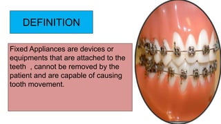
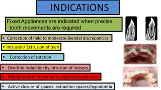
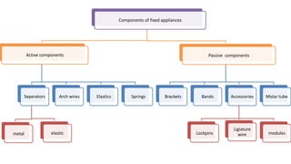
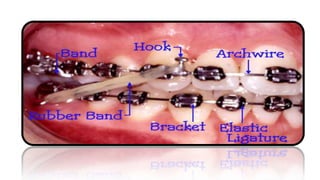
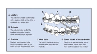
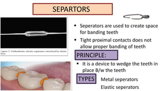
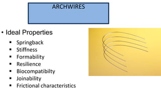
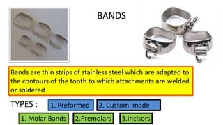
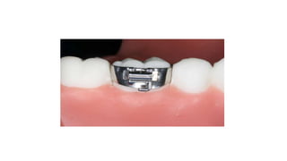
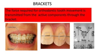
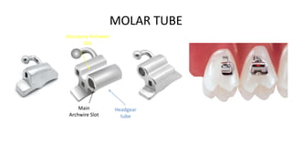
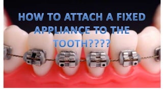
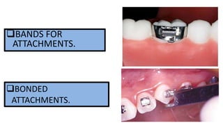
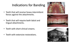
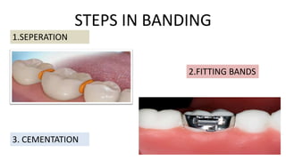
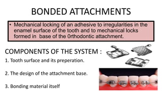
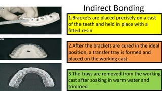
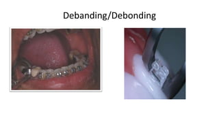
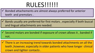
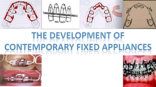
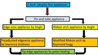
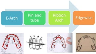
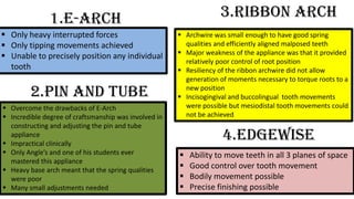
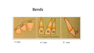
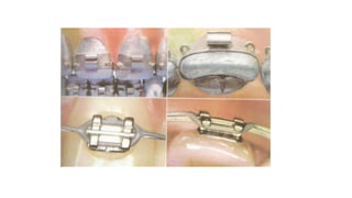


Fixed appliances are devices attached to teeth that cannot be removed by the patient and are used to precisely move teeth. They are indicated when multiple tooth movements are needed. Components include active items like separators, archwires, and elastics, and passive items like brackets, bands, and molar tubes. Separators create space for banding. Archwires apply force in various planes. Bands are used for teeth requiring heavy forces or multiple attachments. Brackets connect teeth to archwires. Molar tubes house archwires and connect to headgear. Early appliances included E-Arches, pin-and-tube, and ribbon arches. Edgewise appliances provided better control but required complex bends. Contemporary appliances


