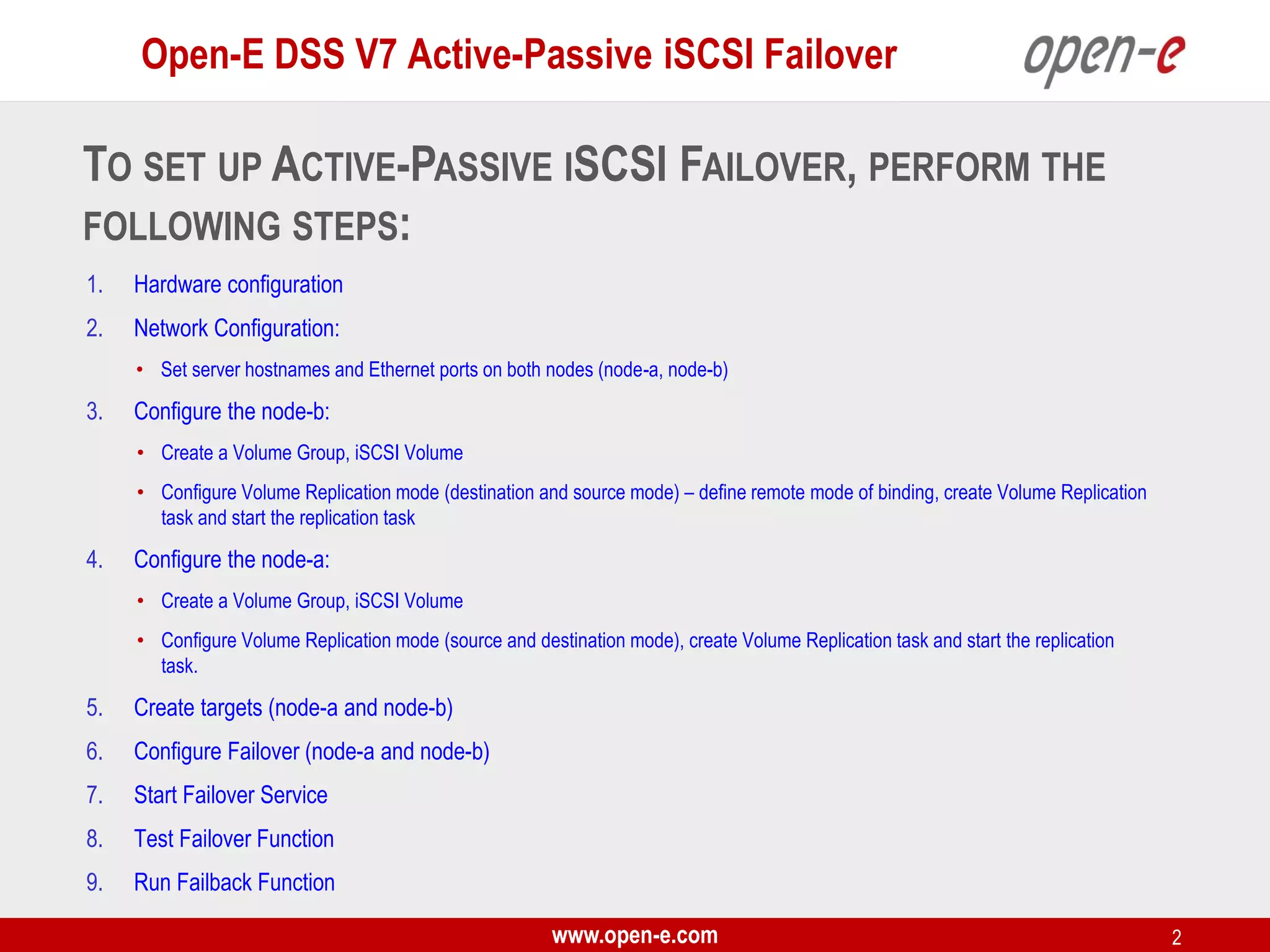
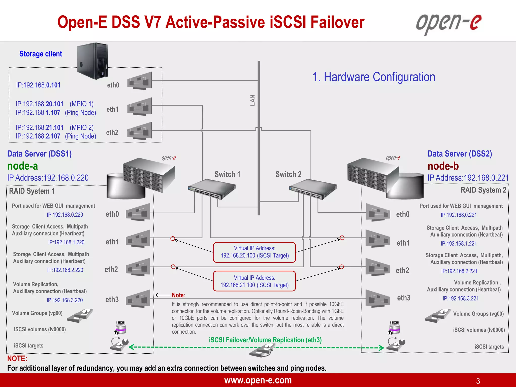
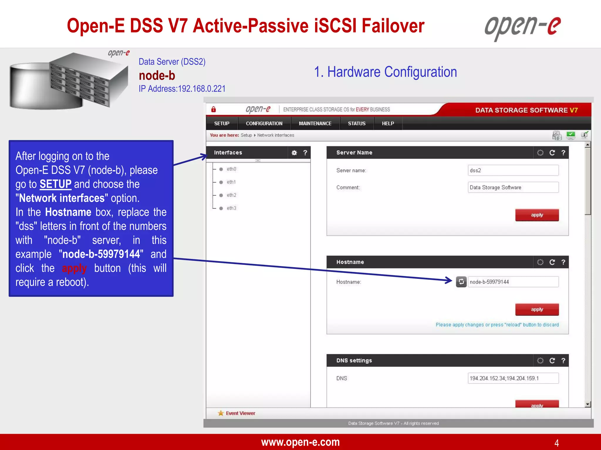
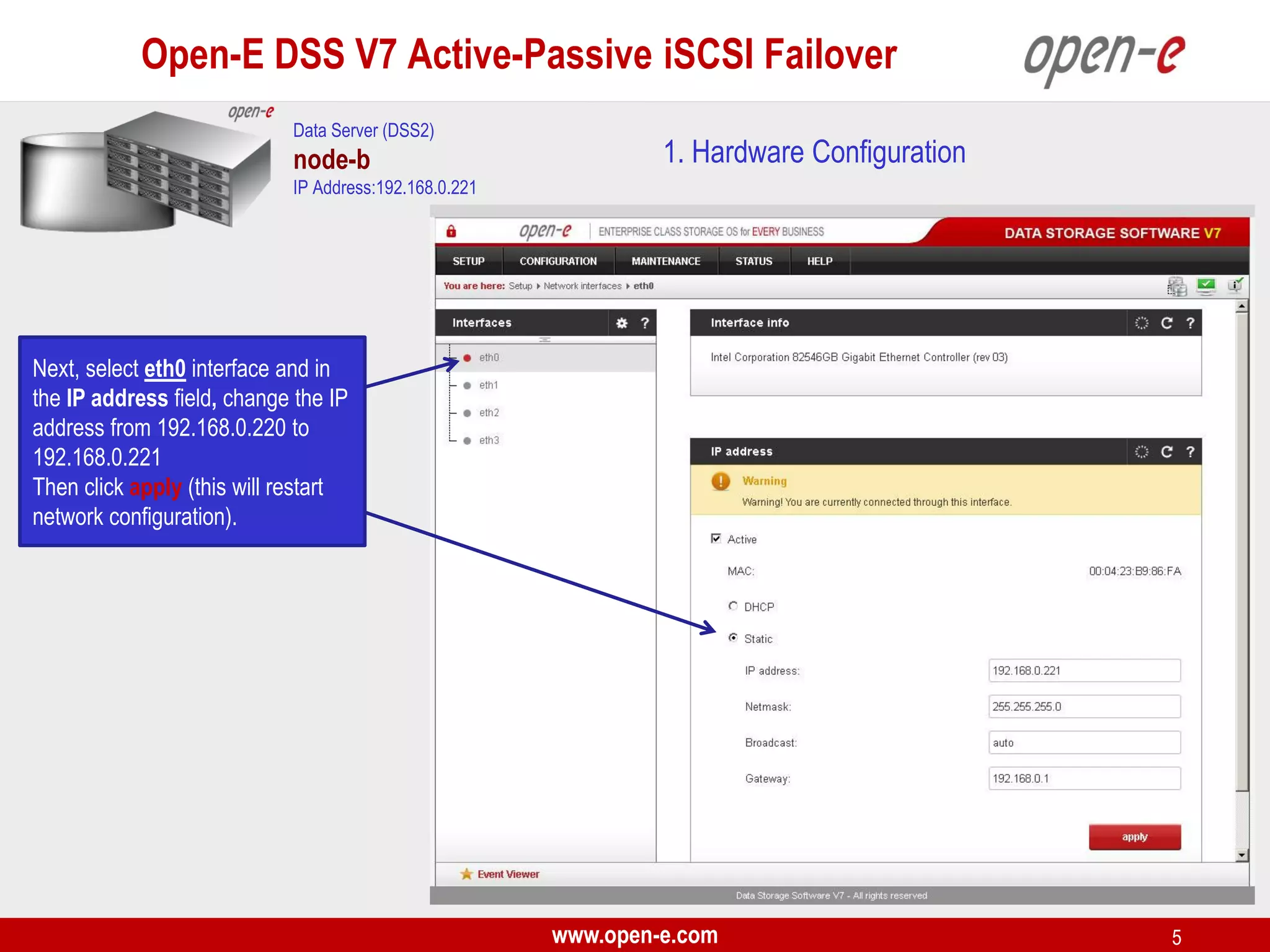
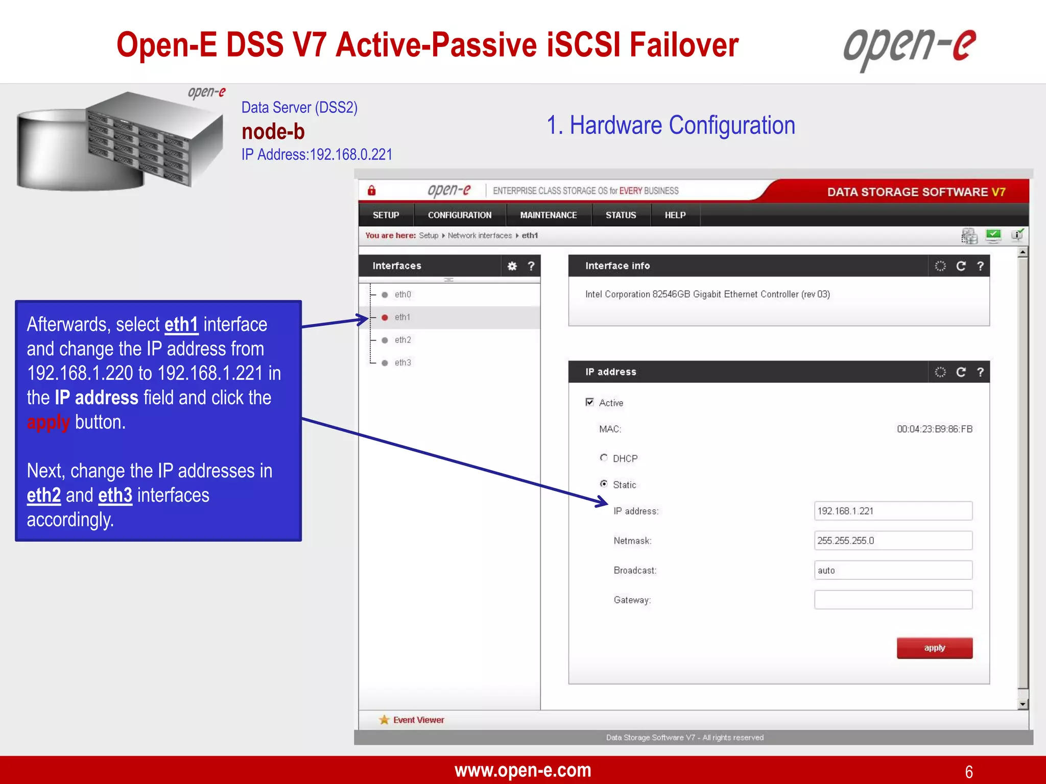
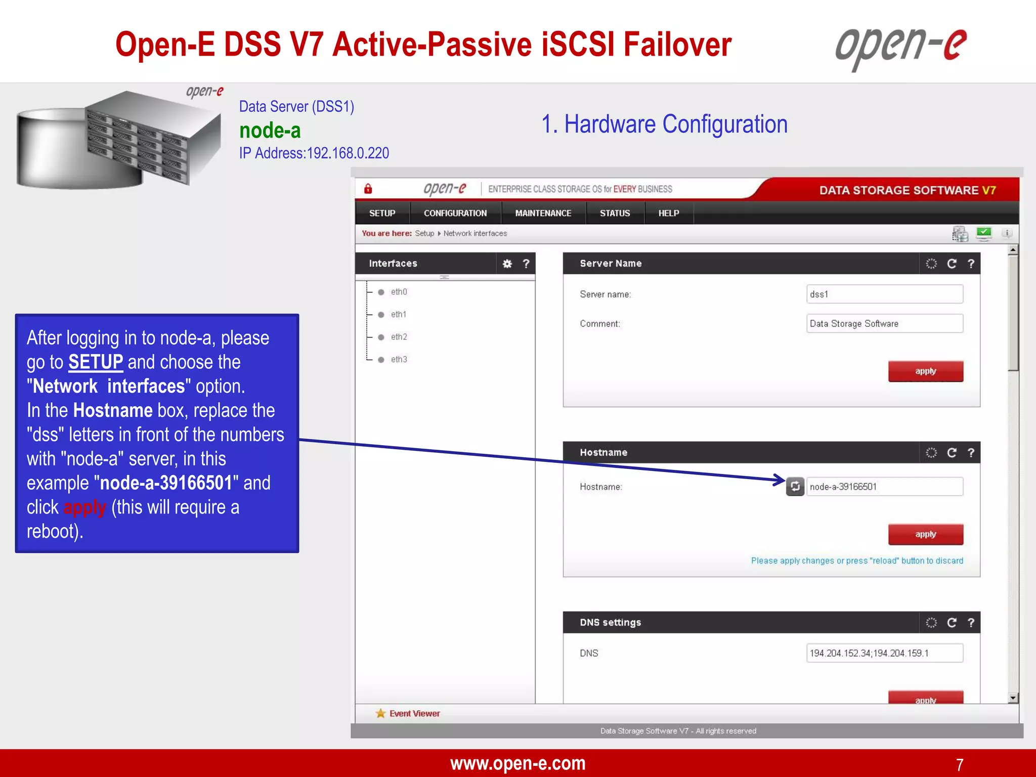
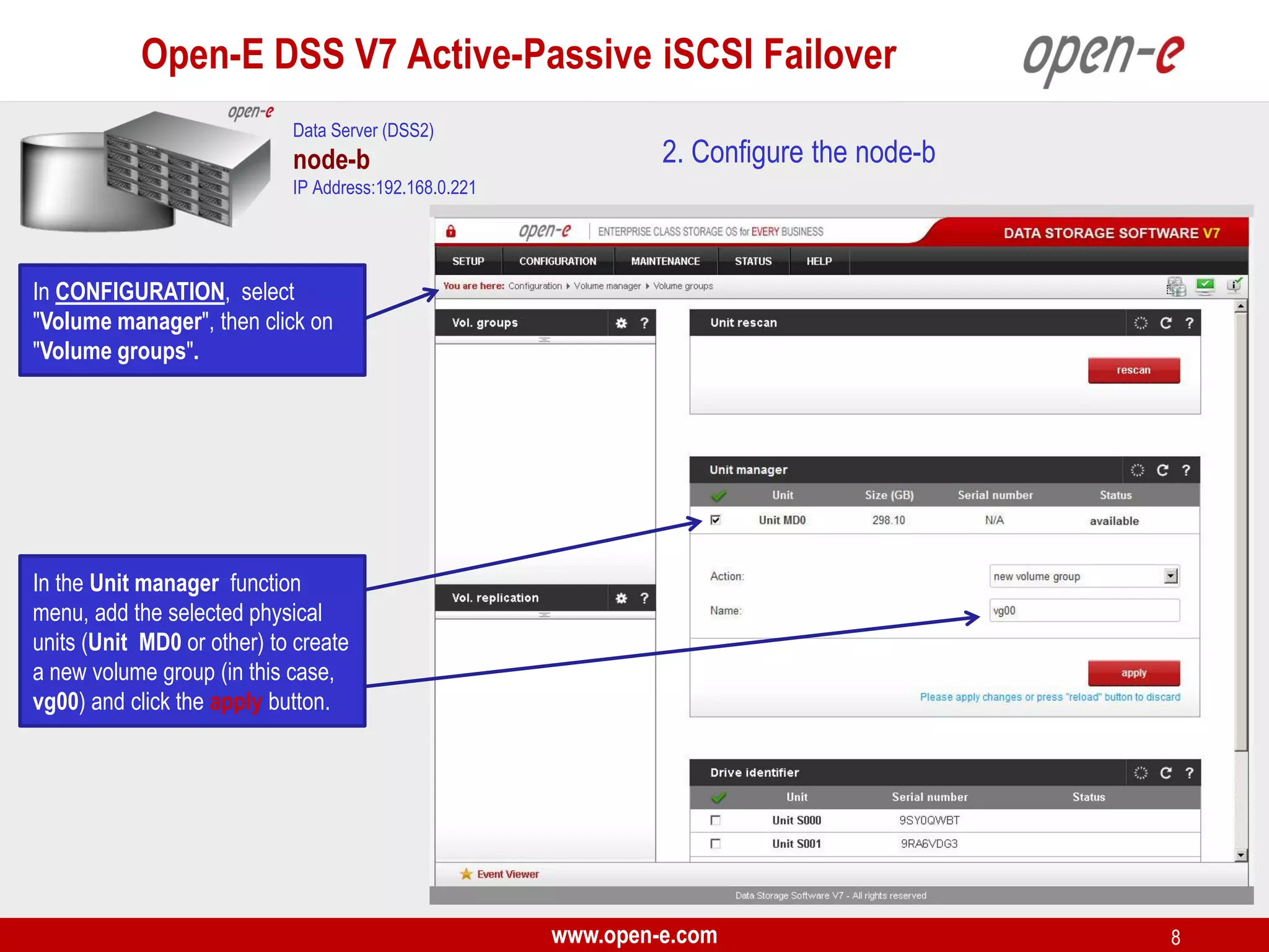
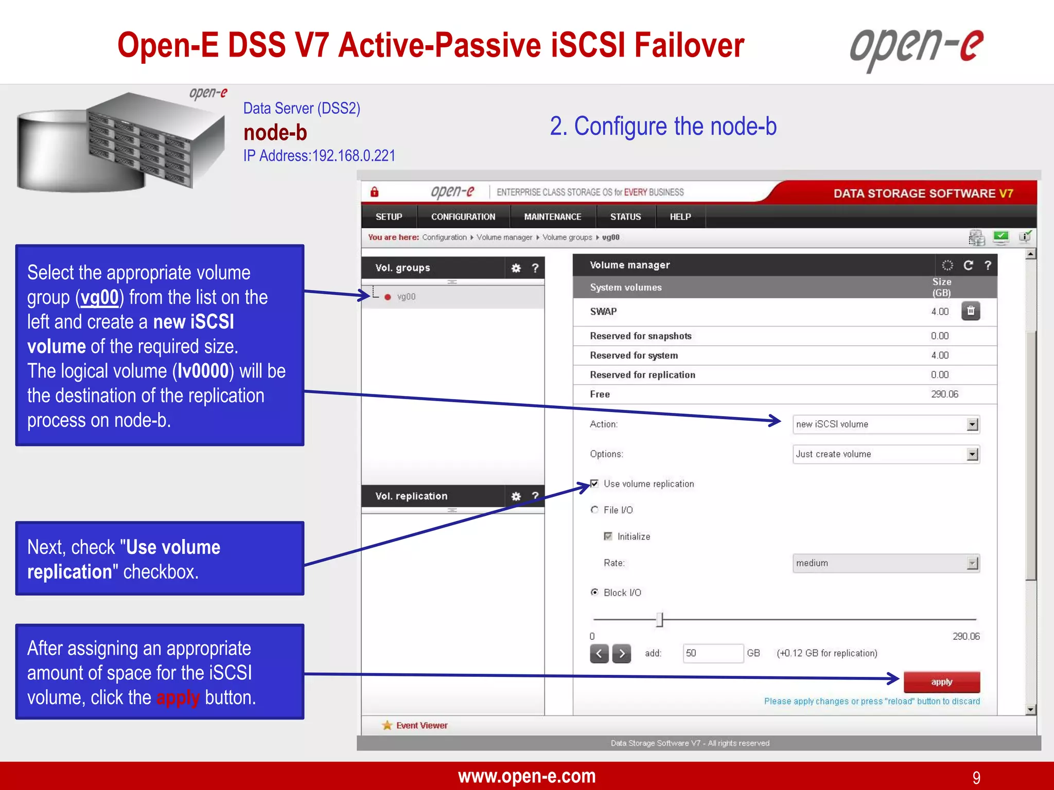
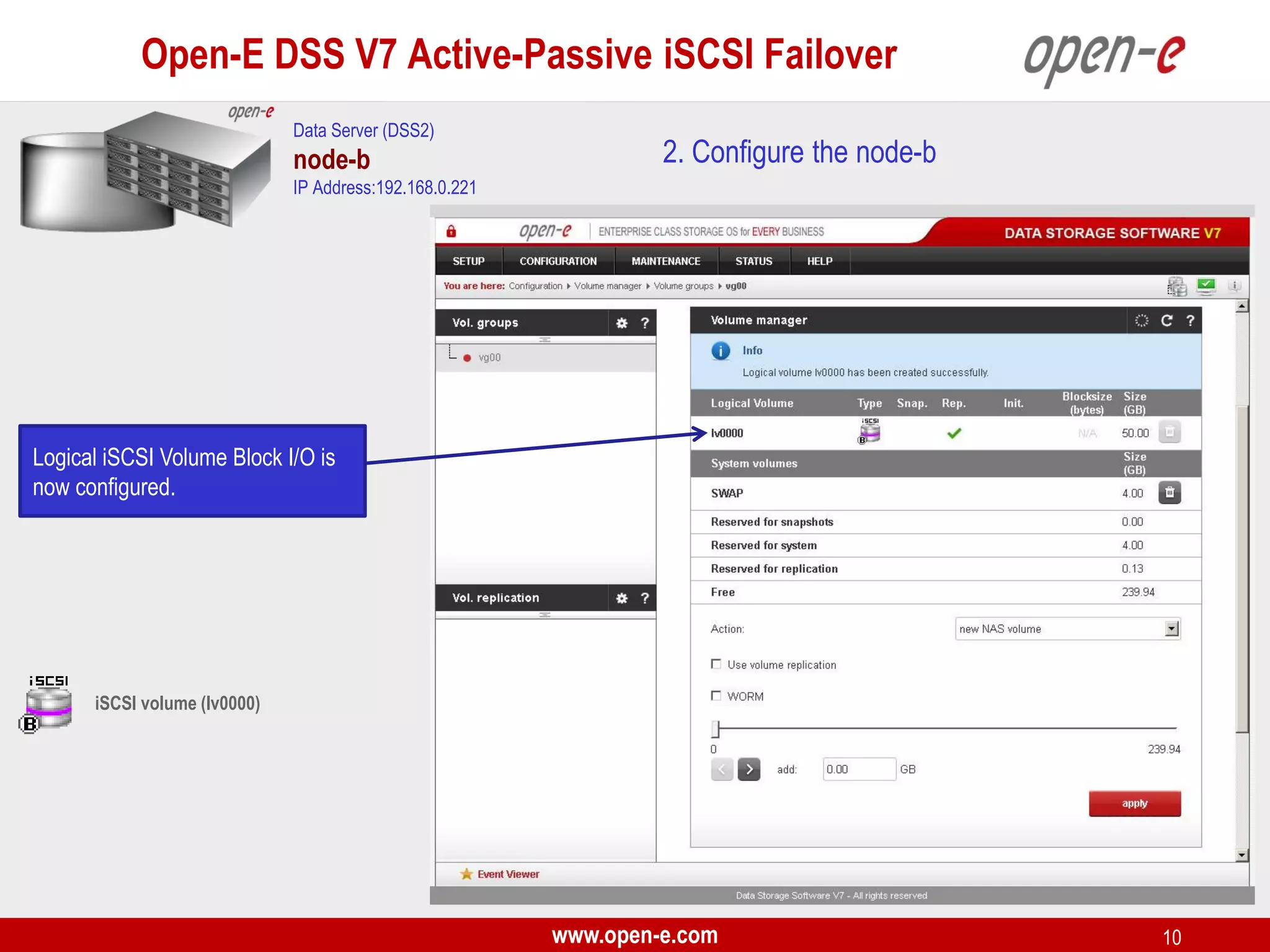
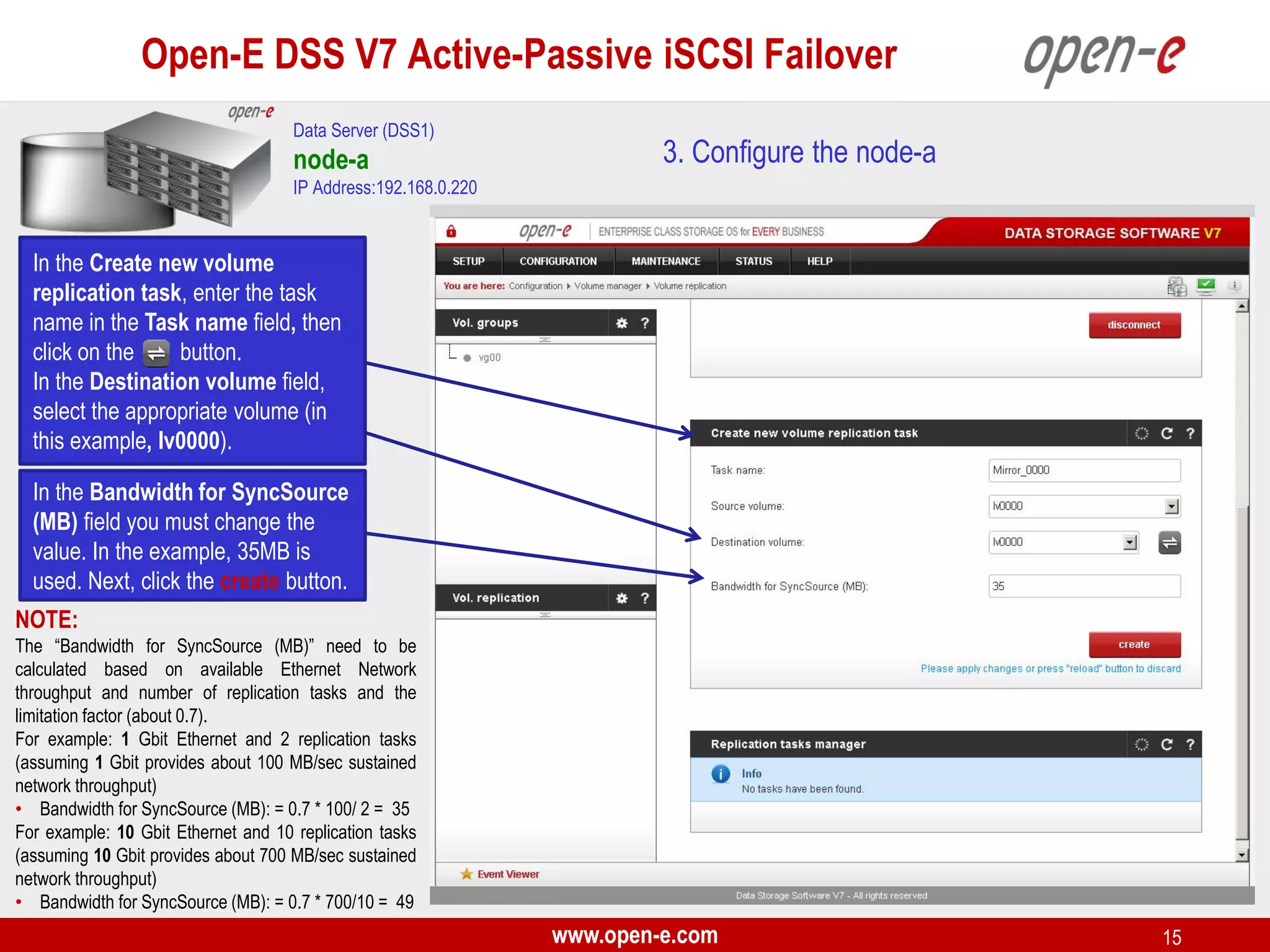
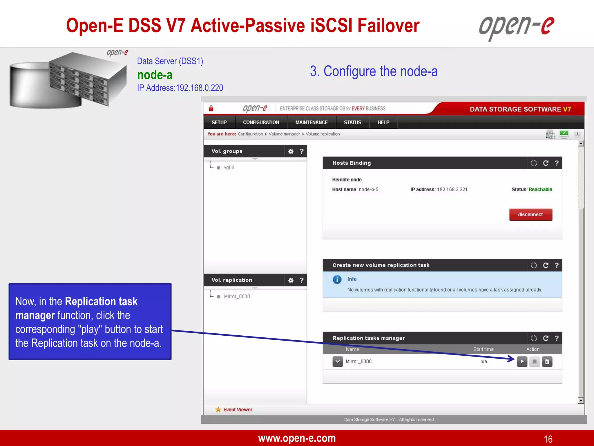
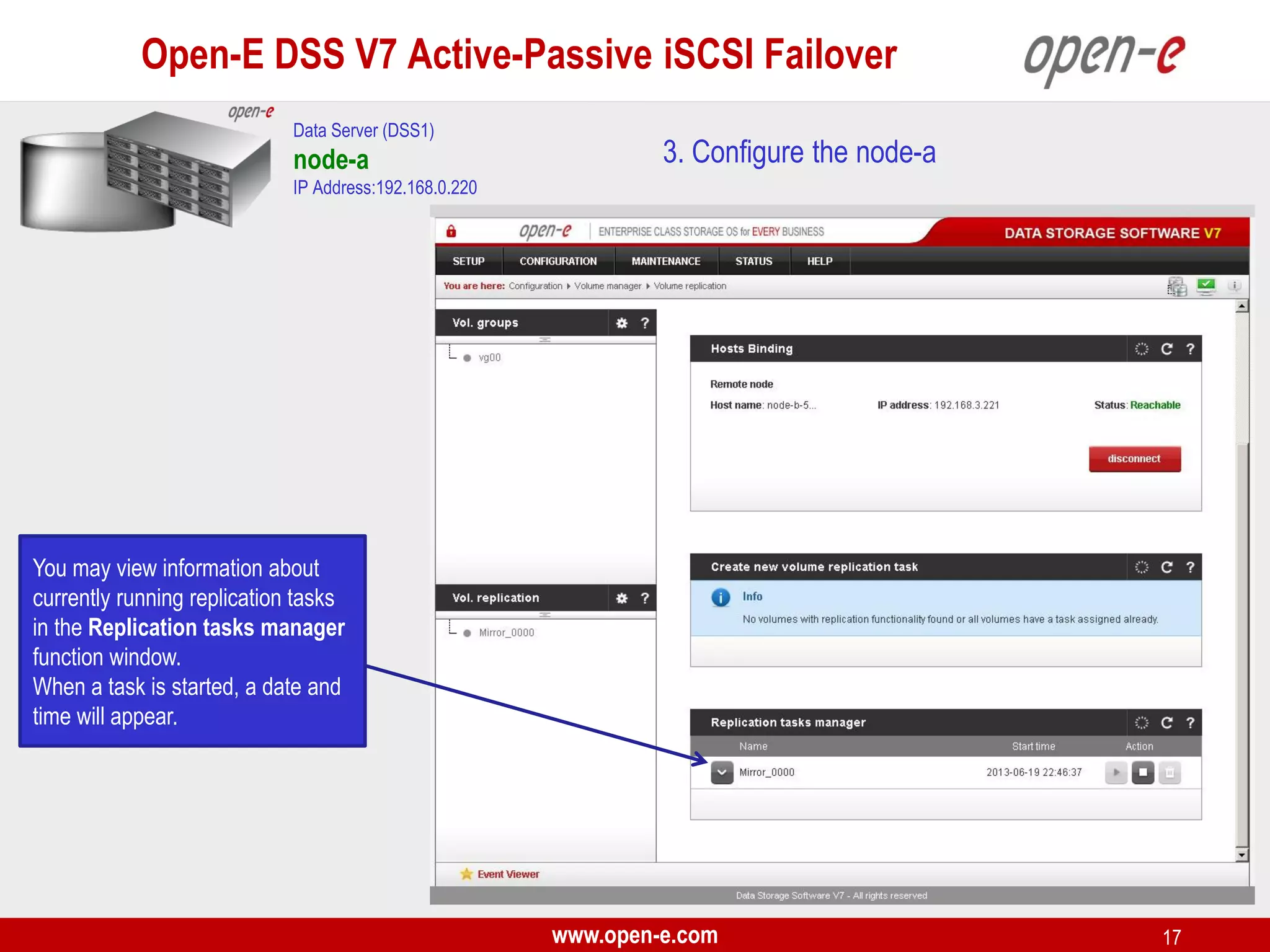
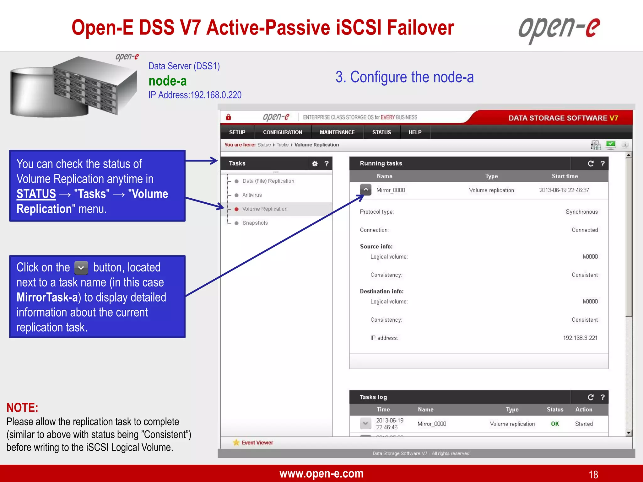
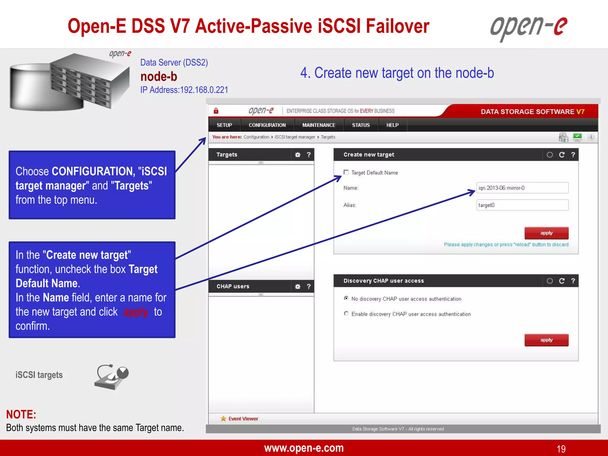
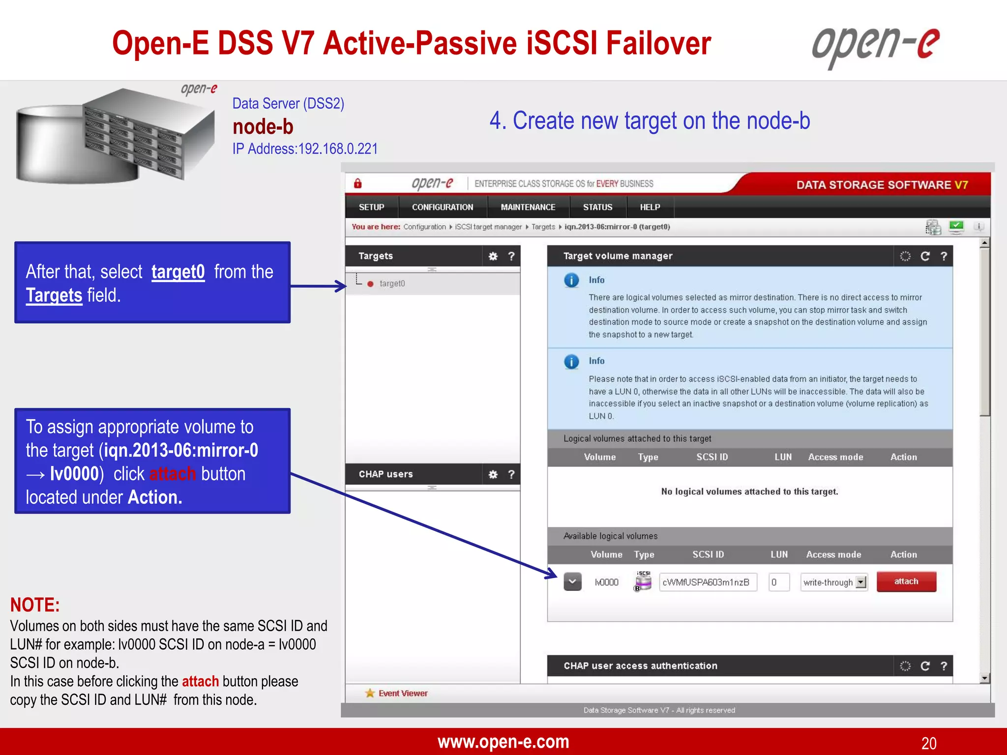
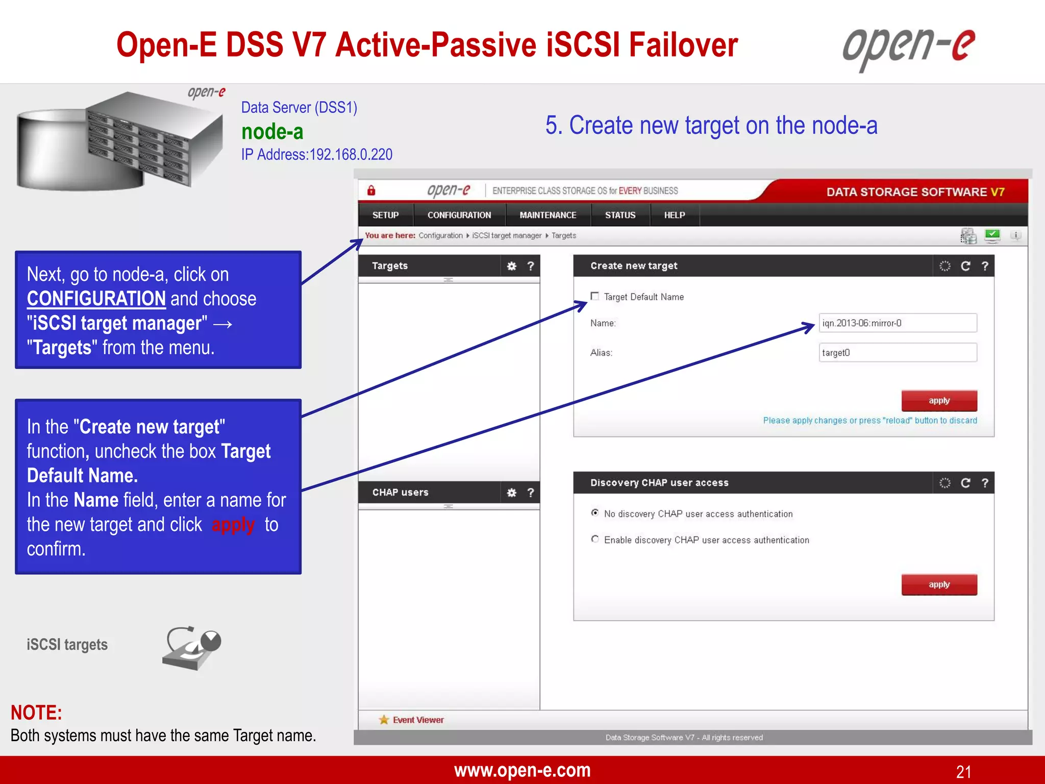
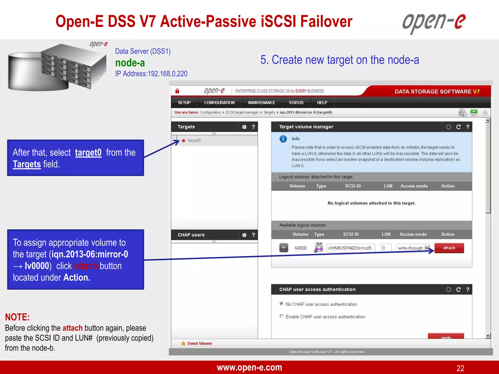
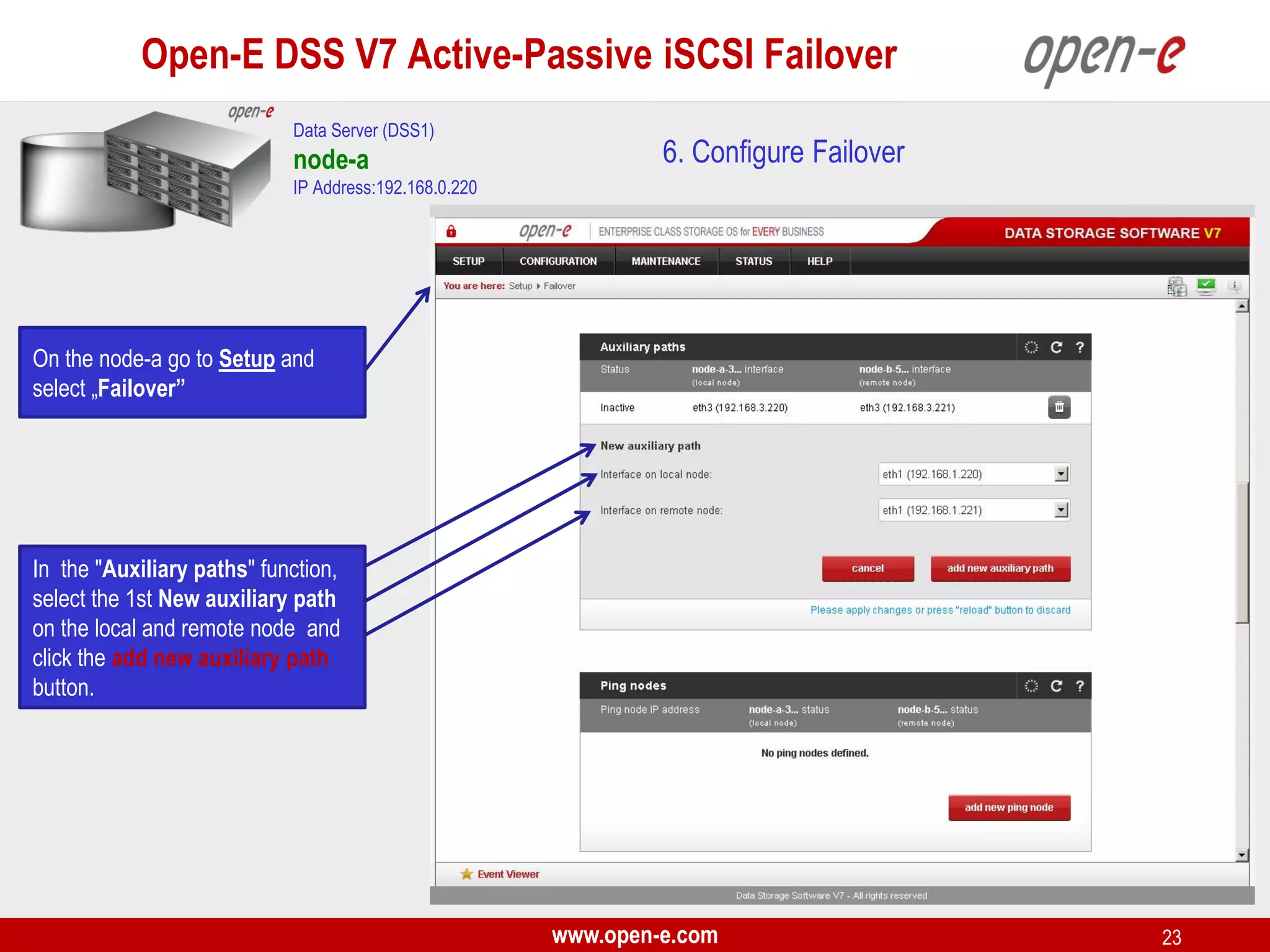
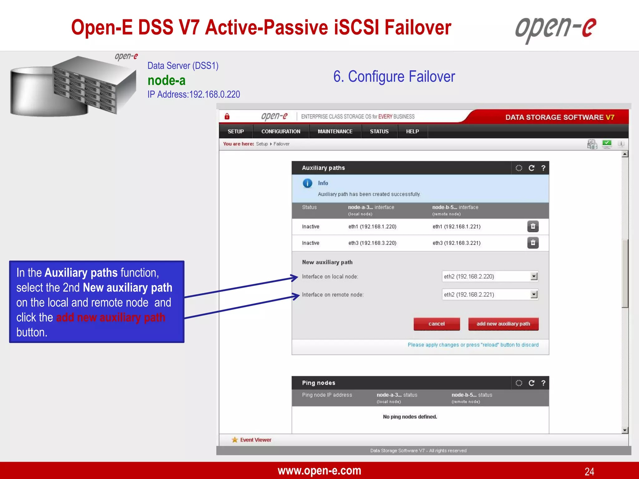
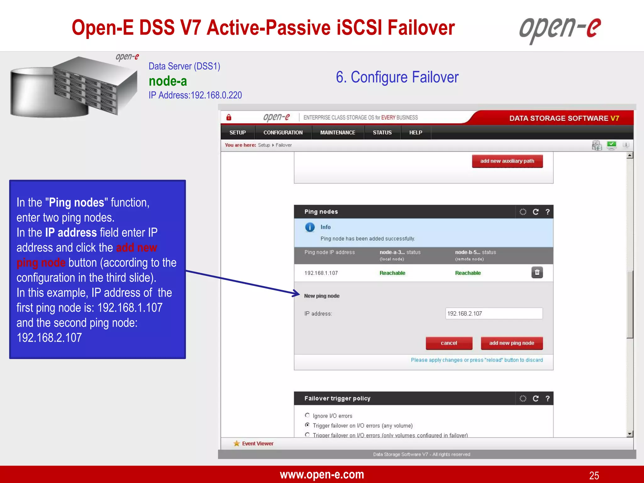
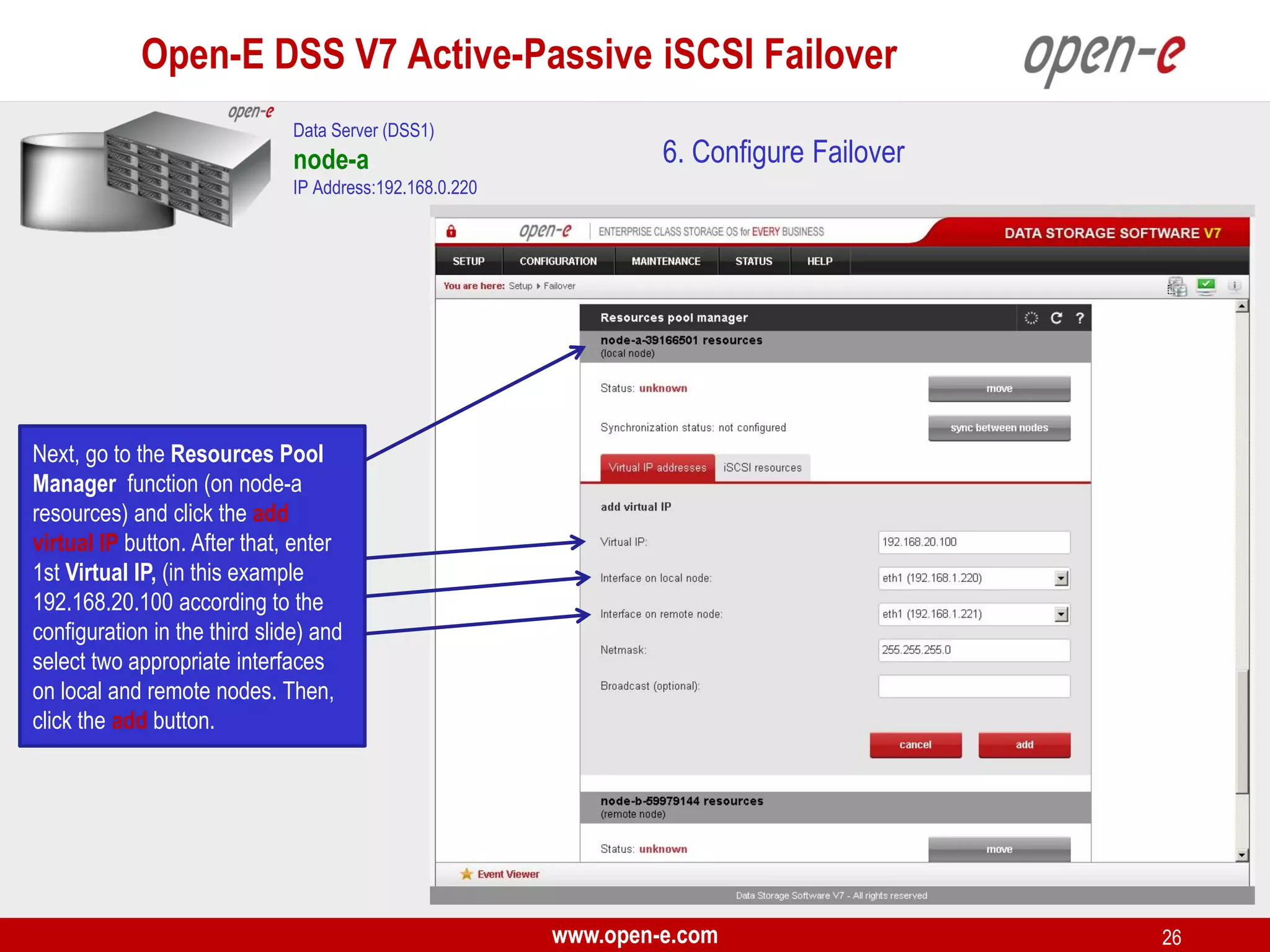
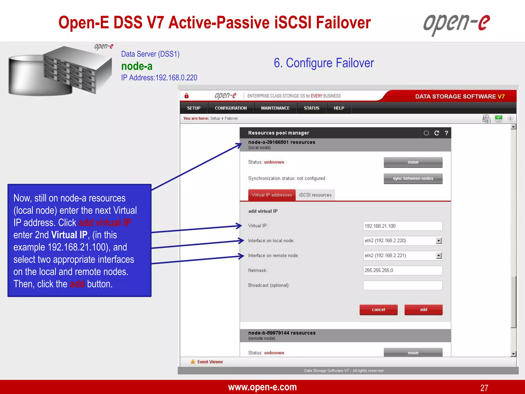
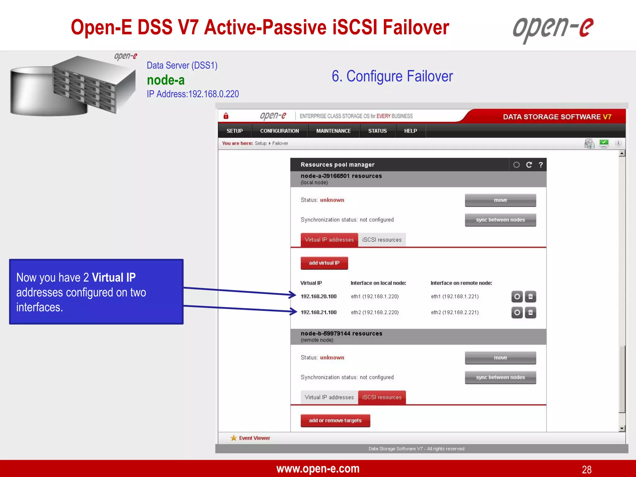
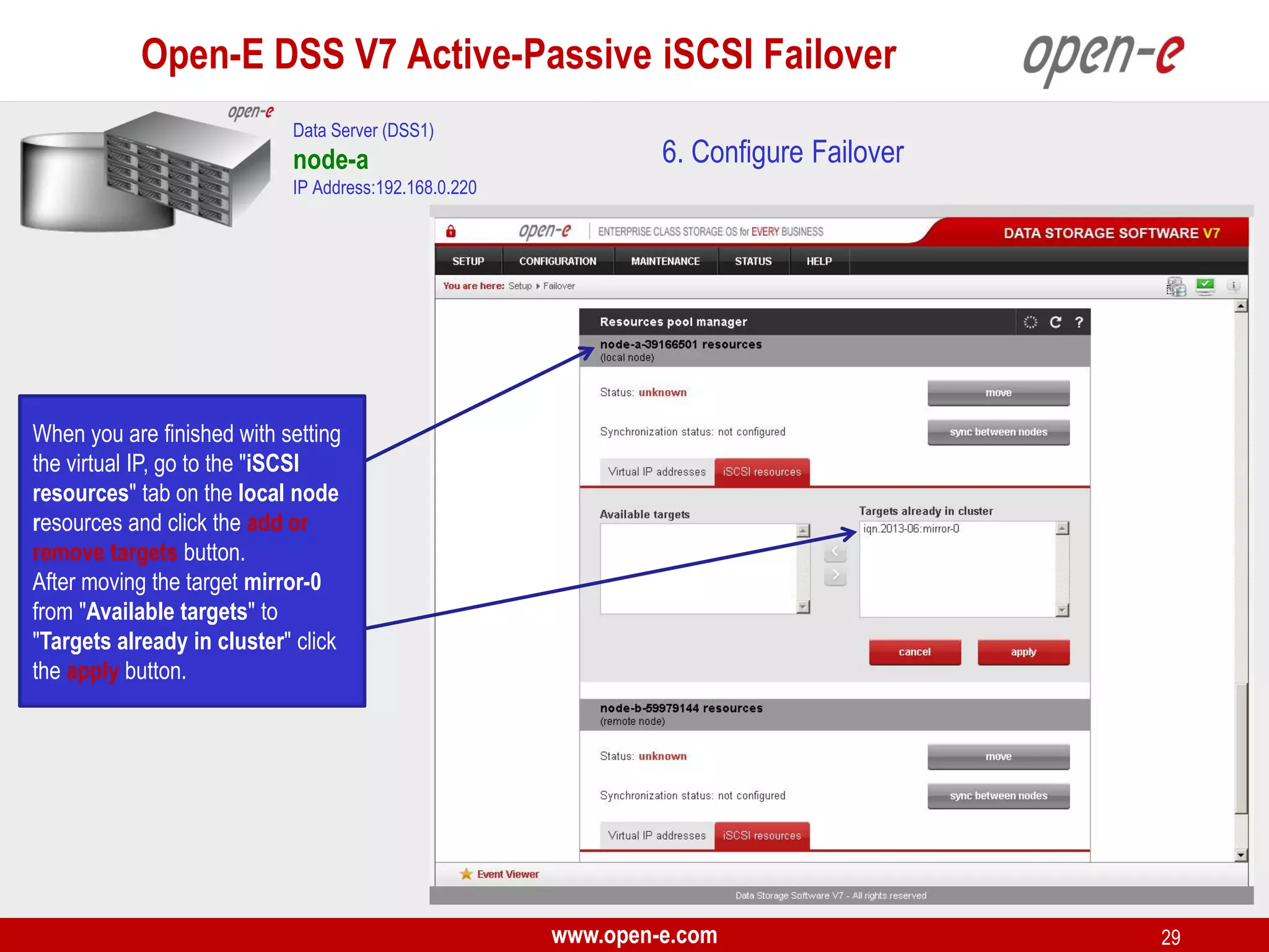
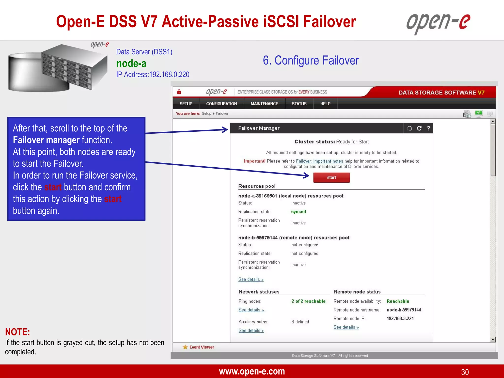
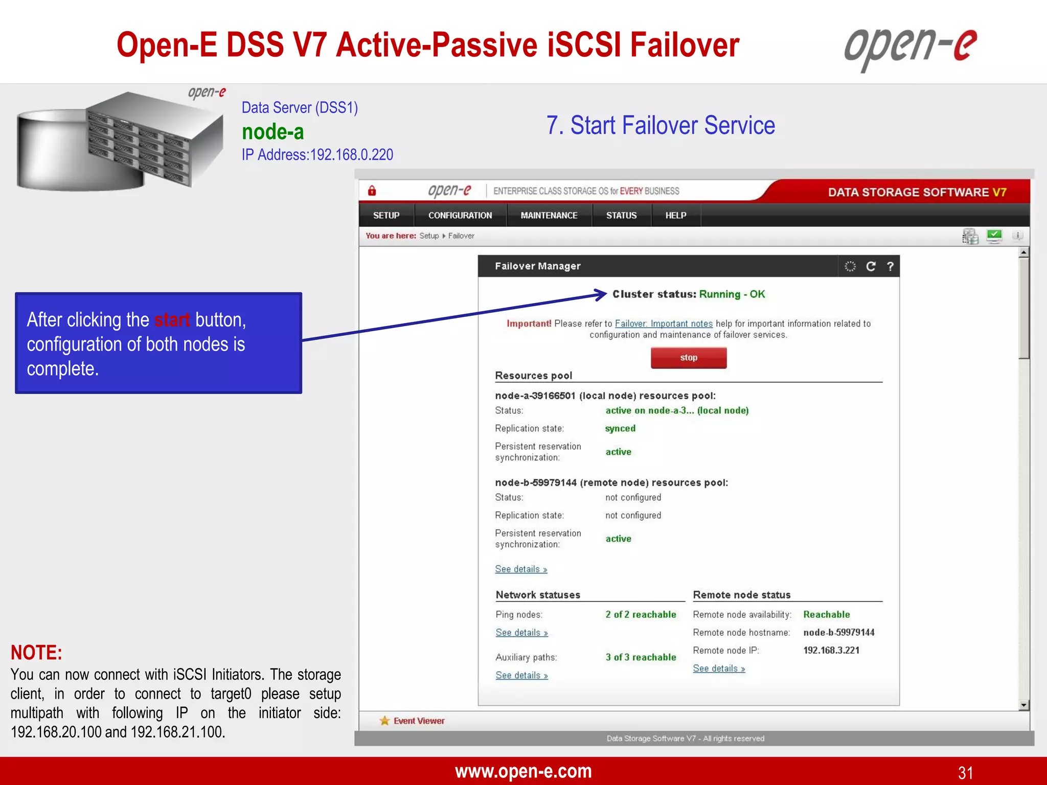
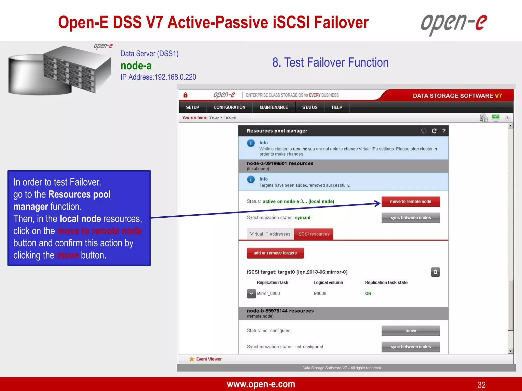
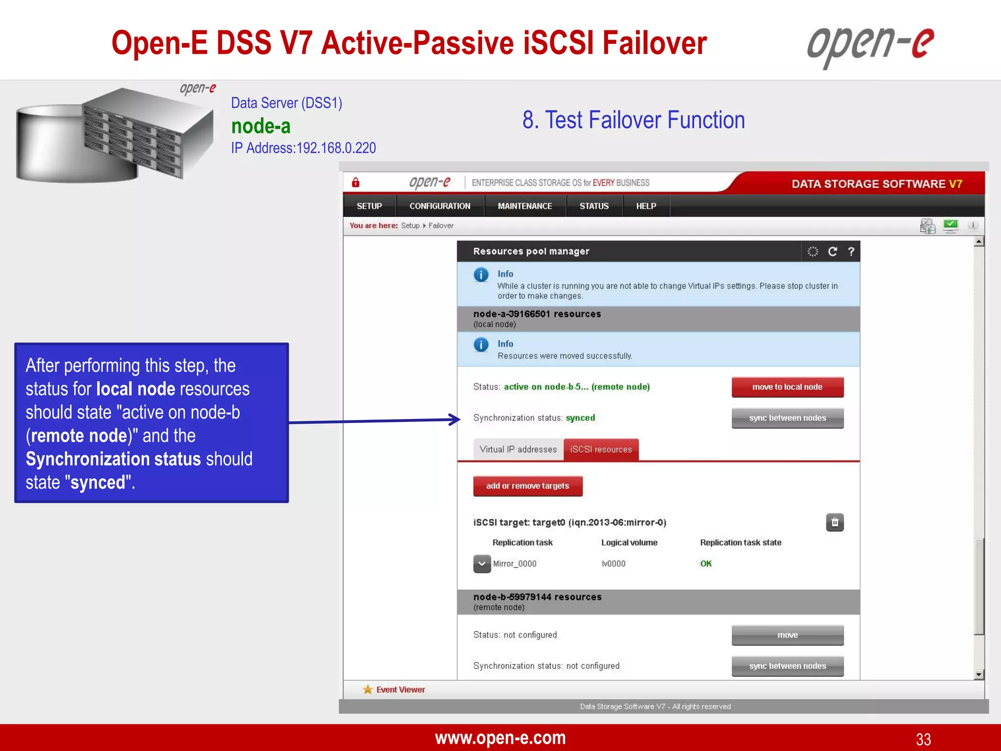
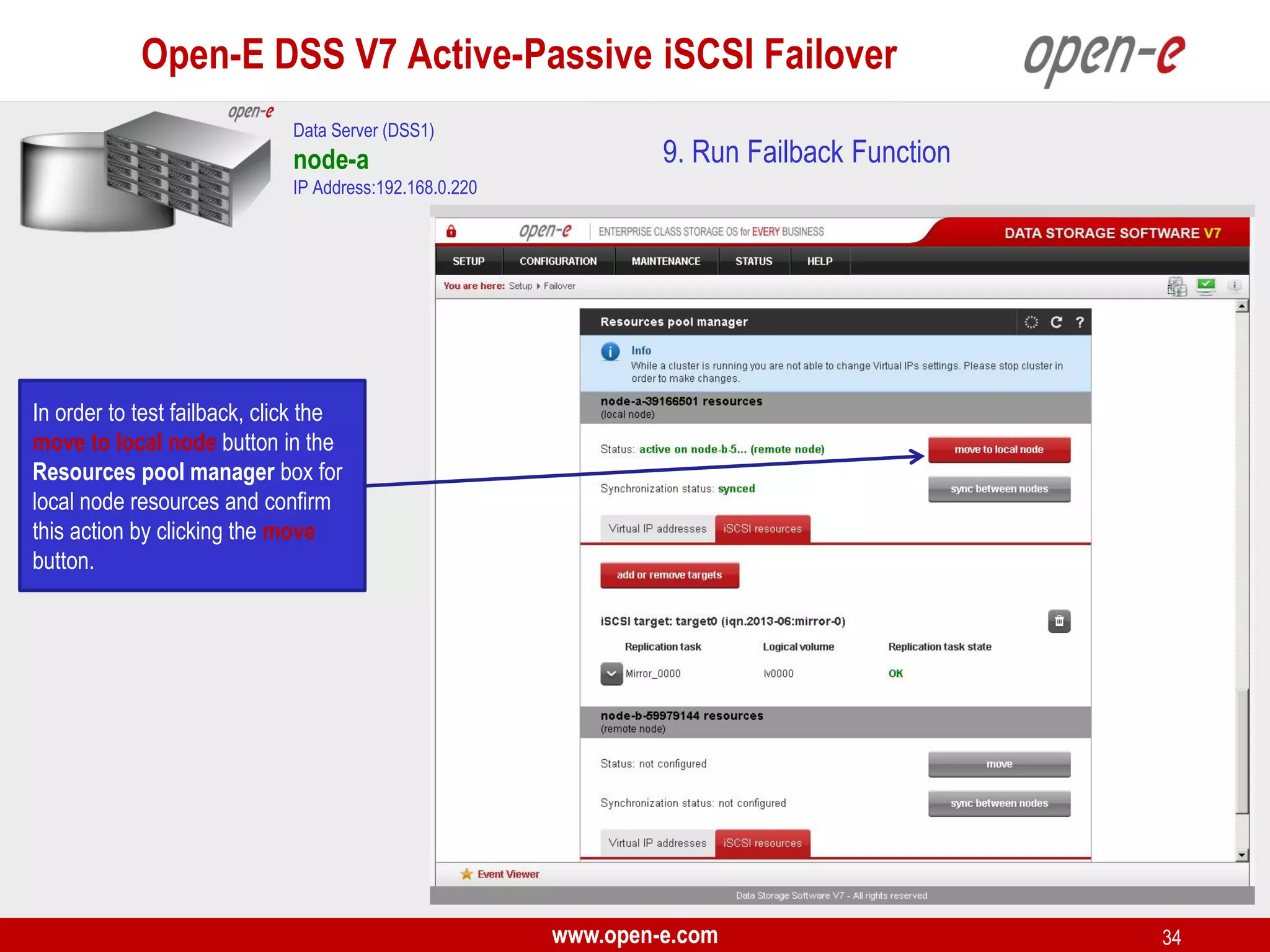
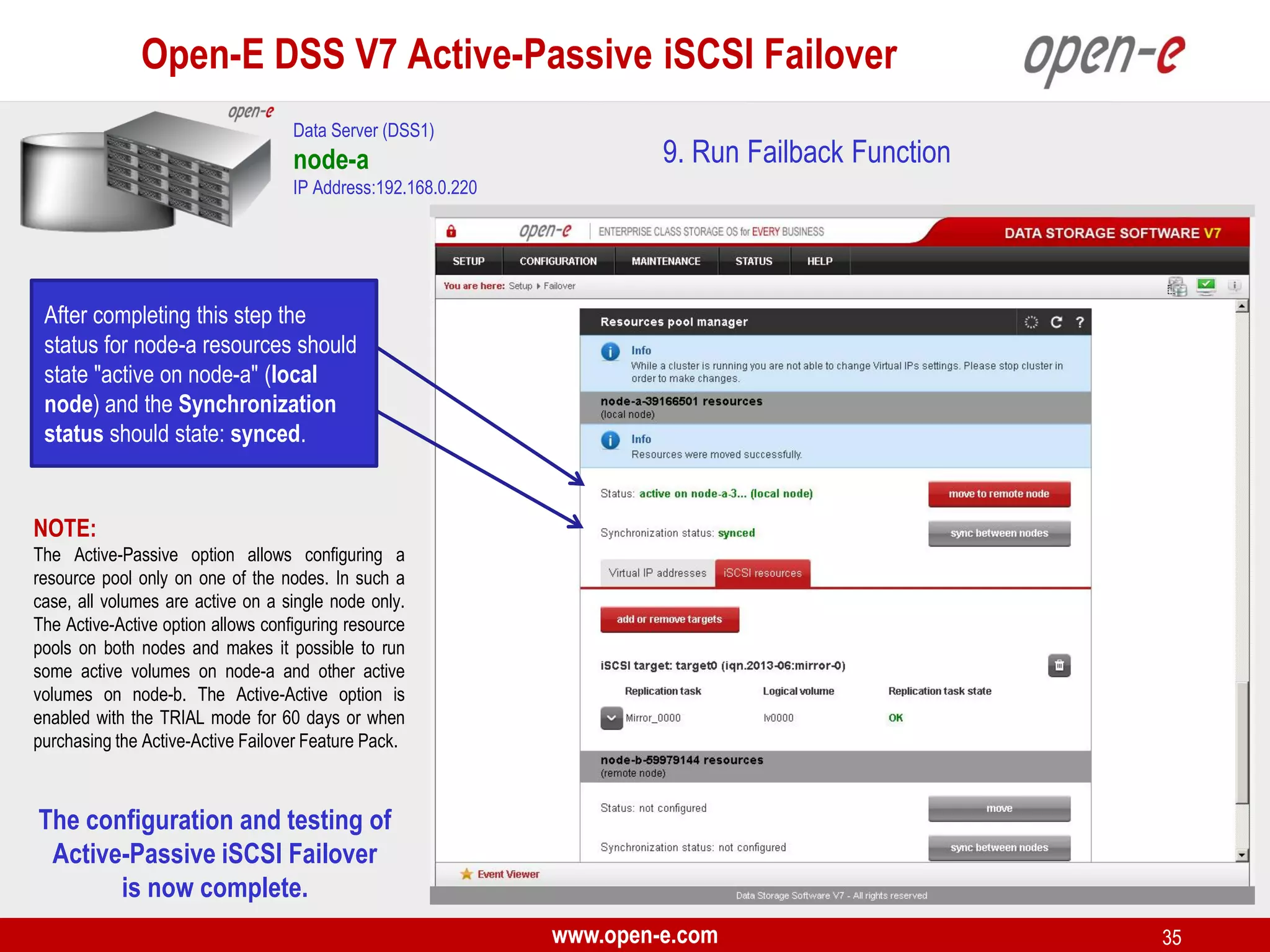
This document provides a step-by-step guide for setting up active-passive iSCSI failover between two Open-E DSS V7 nodes (node-a and node-b). The steps include: 1) configuring the hardware and network settings for each node; 2) creating volume groups and iSCSI volumes for data replication on each node; 3) configuring volume replication between the nodes; 4) creating iSCSI targets on each node; 5) configuring failover settings; and 6) testing the failover functionality. Key aspects involve replicating iSCSI volumes from the active node-a to the passive node-b, and configuring virtual IP addresses and targets on each node for seamless failover
The document provides step-by-step instructions for setting up an active-active load balanced iSCSI high availability cluster without bonding between two Open-E DSS V7 nodes (node-a and node-b). The key steps include:
1. Configuring the hardware for each node including network interfaces and IP addresses.
2. Configuring volumes, volume replication between each node's volumes to enable data synchronization, and starting the replication tasks.
3. Creating iSCSI targets on each node to expose the replicated volumes and enable failover.
The document provides examples of commands for using the Navisphere CLI to manage various aspects of an EMC storage system, such as:
1. Listing front-end port speeds, rebooting the SP, getting disk and RAID group information, setting cache parameters, creating RAID groups, binding and modifying LUNs.
2. Creating storage groups, adding LUNs to storage groups and connecting hosts to storage groups.
3. Summarizing how to calculate the stripe size of a LUN based on the RAID type and number of disks in the RAID group.
The Docker network overlay driver relies on several technologies: network namespaces, VXLAN, Netlink and a distributed key-value store. This talk will present each of these mechanisms one by one along with their userland tools and show hands-on how they interact together when setting up an overlay to connect containers.
The talk will continue with a demo showing how to build your own simple overlay using these technologies.
This document discusses Docker networking and Weave. By default, Docker uses Linux bridges to connect containers to host networks, but containers cannot communicate across hosts. Weave allows containers on different hosts to communicate as if on the same network by launching Weave routers that connect container networks. Weave provides features like multi-datacenter networking, encryption, and container mobility. The document demonstrates launching Weave on multiple VMs and using it to connect containers across different hosts and dynamically attach new containers.
The Docker network overlay driver relies on several technologies: network namespaces, VXLAN, Netlink and a distributed key-value store. This talk will present each of these mechanisms one by one along with their userland tools and show hands-on how they interact together when setting up an overlay to connect containers.
The talk will continue with a demo showing how to build your own simple overlay using these technologies.
This document describes how to deploy a Kubernetes cluster on CoreOS virtual machines including setting up the Kubernetes master and nodes. It details installing software packages, configuring Kubernetes components like etcd and flannel, and creating replication controllers and services to deploy applications. The cluster consists of a master and two nodes with nginx pods load balanced across nodes using a QingCloud load balancer.
Tutorial on using CoreOS Flannel for Docker networkingLorisPack Project
Flannel is an overlay based networking technique for networking Docker containers on CoreOS platforms. This tutorial explains the theory, setup instructions and limtations of the mechanism.
The document discusses different Docker networking drivers including null, host, bridge, overlay, and macvlan/ipvlan networks. It provides examples of creating networks with each driver and how containers on different networks will connect and obtain IPs. Specifically, it shows how the bridge driver sets up a private Docker bridge network (docker0 by default) and how overlay networks use VXLAN tunnels to connect containers across multiple Docker daemons.
Open Source Backup Cpnference 2014: Bareos in scientific environments, by Dr....NETWAYS
To backup 110 (partly virtualized) Linux servers the Max Planck Institute for Radio Astronomy has been using Bareos for 5 years now. The full backup volume is constantly growing and has just passed the 35 TiB mark with up to 6 million files per TiB. Naturally there were problems with scalability and flexibility which needed to be addressed.
We are using 2 Spectra Logic T950 (LTO5/LTO6) tape libraries, 40 TiB of disk backup space, and a dedicated 1GbE/10GbE backup LAN.
As it may be an inspiration to other users, we would like to share our experience utilizing virtual full backups, concurrent jobs, backup of Heartbeat/DRBD Failover Clusters and integrating Bareos with REAR for disaster recovery.
Coming from TSM, passing Bacula on the way, we finally found our destination with Bareos!
The Max Planck Institute for Neurological Research operates several brain scanners for human and animal studies. Imaging techniques used here comprise magnetic resonance imaging (MRI), positron emission tomography (PET), optical imaging and microscopy.
Research is often interdisciplinary, including contributions from the fields of biology, physics, medicine, psychology, genetics, biochemistry, radiochemistry – with very heterogeneous characteristics of data and analysis methods. Backup requirements range between file systems with literally millions of very small files (DICOM raw data or FSL intermediate results) to files of 200 GB+ size (PET listmode).
“Good Scientific Practice” mandates backup/archiving primary data and “everything else needed to reproduce published results” (tools, documentation of tool chains, intermediate results) – which is a veritable challenge in a high-end, dynamic lab environment.
Until recently, we have used a HSM system from Sun/Oracle Inc (SAM-FS) to meet our requirements of backup and archiving, in particular, using HSM-type filesystems for scientific computing in order to have a fine-grained backup.
However, a significantly larger and more powerful system was needed and we are now migrating to a Quantum i6000 (LTO-6) tape library with Grau OpenArchiver as HSM frontend. With help from our colleagues in Bonn (MPI for Radio Astronomy), we were able to use Bareos for archiving some vital filesystems (backup-to-disk using a HSM file system with WORM tapes; one job per file; file archives < 5 GB; mostly unixoid backup clients).
We are very pleased with the performance, ease of handling and flexibility this approach offers, e.g. when using incremental backups of virtual machines, listing the 5 largest files can tell a lot about a system’s “health”; pre- and posthooks allow some interesting security features in an ESX-cluster environment (taking network interfaces automatically up before saving sensitive data and shutting the interfaces down afterwards); analysing backup reports reveal longterm trends for hot spots, etc.
Raul Leite discusses several key NFV concepts and bottlenecks including:
1) NFV architecture which aims for independent hardware, automatic network operation, and flexible application development.
2) Common NFV bottlenecks like packet loss, hypervisor overhead, and low throughput due to CPU and resource allocation issues.
3) Techniques to optimize NFV performance such as SR-IOV, PCI passthrough, hugepages, CPU pinning, and DPDK. SR-IOV and PCI passthrough provide direct access to network hardware while hugepages, pinning and DPDK improve CPU performance.
VyOS now supports VXLAN interfaces which allow multiple L2 segments to be multiplexed over a single physical network. VXLAN uses encapsulation to transport Ethernet frames over IP. The VNI field in VXLAN headers maps frames to different L2 segments. VyOS VXLAN interfaces can be configured and used like physical interfaces for routing, bridging, and protocols like OSPF. However, attributes like the VNI and multicast group cannot be changed after interface creation without deleting and recreating the interface.
Building a Virtualized Continuum with Intel(r) Clear ContainersMichelle Holley
Containers provide benefits like speed, manageability, and ease of use. However, security concerns remain as containers do not offer the same level of isolation as virtual machines. Intel Clear Containers address this issue by adding hardware virtualization support through Intel VT-x to containers, creating a continuum between containers and VMs. They integrate with container ecosystems like Docker and Kubernetes to provide a more secure container runtime while maintaining the benefits of containers like small size and fast provisioning.
Web scale infrastructures with kubernetes and flannelpurpleocean
La capacità di rispondere in poche frazioni di secondo alle richieste degli utenti - indipendentemente dal loro numero - è un fattore determinante per il successo dei servizi sul web. Secondo Amazon, bastano 100 millisecondi di latenza nella risposta per generare una perdita economica di circa l'1% sul
fatturato [1]. In base alle statistiche di Google AdWords, inoltre, il 2015 ha sancito l’ufficiale superamento del numero di interazioni mobile rispetto a quelle desktop [2], con la conseguente riduzione della durata media delle sessioni di navigazione web.
In uno scenario di questo tipo, la razionalizzazione dell’utilizzo delle risorse hardware e la capacità di scalare rispetto al numero di utenti sono fattori determinanti per il successo del business.
In questo talk racconteremo la nostra esperienza di migrazione di soluzioni e-commerce di tipo enterprise in Magento da un’architettura basata su VM tradizionali ad una di tipo software-defined basata su Kubernetes, Flannel e Docker. Discuteremo, quindi, delle reali difficoltà da noi incontrate nel porting su container di soluzioni in produzione e daremo evidenza di come, alla fine di questo lungo viaggio, i nostri sforzi siano stati concretamente premiati dall’aumento di resilienza, affidabilità e automazione della soluzione finale.
A supporto della conversazione, mostreremo i risultati dei benchmark da noi condotti per valutare la scalabilità della nuova architettura presentando delle evidenze delle reali capacità di Kubernetes come strumento di orchestrazione di servizi erogati in Docker container.
Concluderemo l’intervento presentando il nostro progetto di distribuzione geografica dei nodi master di Kubernetes facendo uso di reti SD-WAN per garantire performance e continuità di servizio della soluzione.
This document provides an introduction and overview of installing and configuring the NPACI Rocks cluster distribution. It describes the components of a Rocks cluster including frontend nodes, compute nodes, and the network. It explains the process of installing Rocks which involves booting the frontend from installation media, partitioning and configuring the disk, and installing required software rolls. It also describes how to add compute nodes by using the insert-ethers command and boot them from the Rocks installation disk to join the cluster. The document provides minimum hardware requirements and concludes with how to use the cluster-fork command to distribute commands to all nodes.
The document discusses setting up a Hadoop cluster with CentOS 6.5 installed on multiple physical servers. It describes the process of installing CentOS via USB, configuring basic OS settings like hostname, users, SSH, firewall. It also covers configuring network settings, Java installation and enabling passwordless SSH login. The document concludes with taking server snapshots for backup/recovery and installing Hadoop services like HDFS, Hive etc using Cloudera Express on the cluster.
Linux namespaces and control groups (cgroups) provide isolation and security for Docker containers. Namespaces isolate processes by PID, network, IPC, mount points, etc. Cgroups limit CPU, memory, storage resources. Capabilities and security models like seccomp, AppArmor further harden containers by dropping privileges and blocking risky syscalls. Together, these mechanisms isolate containers and applications from hosts, other containers, and external attacks while still allowing resource sharing through the kernel.
Accelerating Neutron with Intel DPDK from #vBrownBag session at OpenStack Summit Atlanta 2014.
1. Many OpenStack deployments use Open vSwitch plugin for Neutron.
2. But its performance and scalability are not enough for production.
3. Intel DPDK vSwitch - an DPDK optimized version of Open vSwitch developed by Intel and publicly available at 01.org. But it doesn't have enough functionality for Neutron. We have implemented the needed parts included GRE and ARP stacks. Neutron pluging
4. We got 5 times performance improving for netwroking in OpenStack!
Seamless migration from nova network to neutron in e bay productionChengyuan Li
The document summarizes eBay's migration from Nova-network to Neutron networking in their OpenStack production environment. It describes migrating the control plane by setting up new OpenStack and NSX controller nodes, migrating databases, and creating Neutron networks. It then details migrating the data plane by installing Open vSwitch on hypervisors, removing interfaces from Linux bridges, and configuring OVS to connect to the NSX controller. It concludes by discussing post-migration changes needed for reboots and rollbacks.
This document provides instructions for setting up a single server SDN testbed environment using Open vSwitch. It describes installing Ubuntu, configuring networking, installing necessary programs like Open vSwitch and DevStack, and configuring Open vSwitch bridges, tunnels, and virtual machines to emulate an SDN network on a single physical server.
This document discusses Open vSwitch (OVS) and how using Data Plane Development Kit (DPDK) can improve its performance. It notes that with standard OVS, there are many components between a virtual machine and physical networking that cause scalability and performance issues due to context switches. OVS-DPDK addresses this by using polling, hugepages, pinned CPUs, and userspace I/O to bypass the kernel and reduce overhead. The document shows that using DPDK can increase OVS throughput by over 8x and reduce latency by 30-37% compared to standard OVS.
Open Source Backup Conference 2014: Workshop bareos introduction, by Philipp ...NETWAYS
It gives an introduction to the architecture of Bareos, and how the components of Bareos interact. The configuration of Bareos will be discussed and the main Bareos features will be shown. As a practical part of the workshop the adaption of the preconfigured standard backup scheme to the attendees’ wishes will be developed.
Attendees are kindly asked to contribute configuration tasks that they want to have solved.
This document discusses RAID designs on Qsan storage systems. It provides information on RAID groups, which consist of multiple disks. RAID allows for more storage capacity, faster performance, and redundancy. Different RAID levels such as 0, 1, 5 and 6 are supported. Virtual disks can be created within RAID groups and logical unit numbers are assigned to virtual disks to make them accessible to hosts.
Docker Meetup: Docker Networking 1.11, by Madhu VenugopalMichelle Antebi
In this talk, Madhu Venugopal will present Docker Networking & Service Discovery features shipped in 1.11 and new Experimental Vlan network drivers introduced in 1.11.
Can we leverage the resource of public cloud for gaming, streaming, transcoding, machine learning and visualized CAD application on demand? Yes if it provides the capability and infrastructure to utilize GPUs. Can we get high performance networking in the cloud as what I have in the bare metal environment? Yes with SR-IOV. How to achieve them? In this presentation we describe Discrete Device Assignment (also known as PCI Pass-through) support for GPU and network adapter in Linux guest and SR-IOV architectures of Linux guest with near-native performance profile running on Hyper-V. We also will share how to integrate accelerated graphics and networking capabilities in Microsoft Azure infrastructure.
[네이버오픈소스세미나] Maglev Hashing Scheduler in IPVS, Linux Kernel - 송인주NAVER Engineering
This document discusses load balancing problems in container clusters and proposes using the IPVS Maglev hashing scheduler to provide an efficient and reliable load balancer. It describes how traditional load balancing approaches like static routing and ECMP can cause issues like disruption when containers are added or removed. The Maglev hashing algorithm is presented as a solution to provide consistent hashing for high availability. The document outlines implementing Maglev hashing in the IPVS module of the Linux kernel to leverage netfilter for packet processing and forwarding while avoiding issues of traditional load balancers. This achieves an efficient and reliable load balancer that can hash consistently without connection loss, even if load balancers fail.
Open-E DSS V7 Synchronous Volume Replication over a LANopen-e
The document provides step-by-step instructions for setting up synchronous volume replication between two Open-E DSS servers over a local area network. It involves configuring hardware, networking, creating logical volumes on the source and destination nodes, setting up replication between the volumes, and creating a replication task to synchronize data from the source to destination volume. The status of replication can be monitored by checking the replication tasks in the DSS management interface.
StarWind Virtual SAN is software that eliminates the need for physical shared storage infrastructure by mirroring internal hard disks and flash between servers. It reduces capital and operational costs for SMBs, ROBOs, and cloud/hosting providers by starting with just two nodes and scaling out infinitely without dedicated SAN/NAS hardware. Performance is maintained through proprietary technologies like adaptive caching and deduplication that reduce I/O paths compared to traditional storage networks.
StarWind Virtual SAN is entirely software-based, hypervisor-centric virtual machine storage. It creates a fully fault-tolerant and high-performing storage pool that is built for the virtualization workload “from scratch”. StarWind Virtual SAN basically “mirrors” inexpensive internal storage between hosts. Virtual SAN completely eliminates any need for an expensive SAN or NAS or other physical shared storage. It seamlessly integrates into the hypervisor for unbeatable performance and exceptional simplicity of use.
This document provides steps to configure multipath I/O (MPIO) on an Open-E DSS V6 system with VMware ESXi 4.x and a Windows 2008 virtual machine. It requires two network cards in both systems connected to a switch. The steps include configuring the DSS V6 as an iSCSI target with two IP addresses, creating two vmkernel ports on the ESXi host connected to different network cards, adding the DSS as two iSCSI targets, enabling round robin path selection, and installing the Windows VM to test I/O performance using Iometer.
This document summarizes a workshop on network automation tools including Chef and Zero Touch Provisioning.
The agenda includes demonstrating ZTP to boot three bare metal switches, using Chef to orchestrate the baseline configuration of two switches and enforce configuration statements, creating a VXLAN tunnel between two leaf switches using Cisco's CVX, and starting an Opendaylight controller to configure Openflow on switches.
The workshop will require some Virtualbox experience and a notebook with at least 4GB RAM and 10GB storage. Software needed includes Virtualbox, Hypervisor, and virtualization solutions. Attendees should be DevOps engineers interested in the network side of DevOps.
The workshop will prepare VMs, demonstrate
NETMAX TECHNOLOGIES provides network training, software training, and embedded systems support and consultancy. Courses include CCNA, CCNP, Red Hat Linux, Windows, C, C++, Java, .NET, and microcontroller training. It uses NAT to allow private networks to connect to the internet using a limited number of public IP addresses. Static NAT maps a private IP to a public IP in a 1:1 ratio. Dynamic NAT maps private IPs to public IPs from a pool. Overloading NAT maps multiple private IPs to one public IP using port addressing.
This document provides instructions for configuring multiple virtual machines to simulate a computer network as part of a skills competition. It describes setting up Active Directory, DNS, PKI, GPOs, file sharing, and other services on Windows servers. It also includes tasks for configuring a Linux server with Radius, NTP, DHCP, and other network services. Finally, it outlines configuring a router and switch with VLANs, ACLs, and other network security features. The goal is to integrate all the virtual systems and services into a functioning private network.
The document provides instructions for setting up a backup from a DSS V6 data server to an attached tape drive. The key steps include: 1) Configuring hardware and volume groups, 2) Creating NAS volumes and snapshots, 3) Configuring the backup to use the tape drive by defining pools, tasks, and schedules, and 4) Performing backups that store data from network shares on labeled tapes according to the defined configuration.
This document provides an overview of Open vSwitch, including what it is, its main components, features, and how it can be used to build virtual network topologies. Open vSwitch is a software-defined networking switch that can be used to create virtual networks and handle network traffic between virtual machines and tunnels. It uses a distributed database, ovsdb-server, and a userspace daemon, ovs-vswitchd, to implement features like virtual switching, tunneling protocols, and OpenFlow support. Examples are provided for using Open vSwitch with KVM virtual machines and GRE tunnels to create virtual network topologies.
The document discusses the benefits of using Istio service mesh to connect microservices. Istio provides a standard sidecar proxy that handles tasks like load balancing, failure recovery, metrics collection, and traffic management for microservices. It also provides interfaces to configure and manage policies separately from application code. This allows clear separation between application development and operations tasks like routing, monitoring, and access control configuration.
OAM 3G Network Ericsson discusses operation and maintenance of Ericsson's 3G radio access network. Session 1 covers the OSS, EMAS and other tools used for network operation. Session 2 discusses commissioning radio base stations, replacing modules, backing up network nodes, and upgrading base station capacity. Key tools include OSS, EMAS, element manager and scripts for configuration tasks. Proper planning, tools and procedures are needed for tasks like commissioning, module replacement, backups and hardware upgrades.
AWS Fargate makes running containerized workloads on AWS easier than ever before. This session will provide a technical background for using Fargate with your existing containerized services, including best practices for building images, configuring task definitions, task networking, secrets management, and monitoring.
Openstack 3 node setup using RDO on top of RHEL 7.
Complete steps which will give you more convenience to work on top of Openstack without any installation issues.
Open Source Summit 2018, Vancouver (Canada): Workshop by Josef Adersberger (@adersberger, CTO at QAware) and Michael Frank (Software Architect at QAware)
Abstract:
Istio service mesh is a thrilling new tech that helps getting a lot of technical stuff out of your microservices (circuit breaking, observability, mutual-TLS, ...) into the infrastructure - for those who are lazy (aka productive) and want to keep their microservices small. Come one, come all to the Istio playground:
(1) We provide an overview of all current Istio features on a YAML and CLI level.
(2) We guide you through the installation of Istio on a local Kubernetes cluster.
(3) We bring a small sample application.
(4) We provide assistance in the case you get stuck ... and it's up to you to explore and tinker with Istio on your own paths and with your own pace.
*** Please find prerequisites and content here: https://github.com/adersberger/istio-playground ***
The document provides instructions for backing up data from a DSS V6 server to an attached tape library. The 4-step process includes: 1) configuring hardware and logical volumes, 2) creating NAS shares and snapshots, 3) configuring backup tasks and schedules to alternate between tape pools on odd and even weeks, and 4) setting up a restore task to recover data from backup tapes. When completed, the backup and restore processes are automated to run on a weekly schedule and maintain multiple versions of backed up data on tapes.
1. Configure VLANs to separate servers and clients in each organization.
2. Configure NAT inside and outside interfaces on routers.
3. Use static NAT to expose a server to the internet with port forwarding.
4. Use dynamic NAT with overload for internet access for internal clients, sharing a public IP.
This allows internal clients to access external servers while protecting internal servers from direct internet access. The ISP provides public IPs for NAT translations between the private and public networks.
Similar to Open-E DSS V7 Active-Passive iSCSI Failover (20)
The document provides information on how snapshots work in Open-E software. Snapshots allow creating an exact copy of a logical volume at a point in time, while the original data continues to be available. The snapshot is implemented using copy-on-write, where changed blocks are copied to reserved space before being overwritten. This allows mounting snapshots read-only to access past versions of data. The document discusses snapshot configuration, advantages like non-disruptive backups, and disadvantages like decreased write speeds with many active snapshots.
Step-by-Step Guide to NAS (NFS) Failover over a LAN (with unicast) Supported ...open-e
The document provides step-by-step instructions for configuring NAS (NFS) failover over a LAN using Open-E DSS. It describes setting up two servers with mirrored volumes, so that if the primary server fails, operations can fail over to the secondary server. The steps include 1) configuring the network interfaces and bonding on each server, 2) creating mirrored volumes and configuring replication on the primary and secondary servers, and 3) enabling NFS and sharing the volume to allow access from clients. This configuration provides data redundancy and high availability over a local network.
Open-E DSS V6 How to Setup iSCSI Failover with XenServeropen-e
The document provides instructions for setting up DSS V6 iSCSI failover with XenServer using multipath, which includes configuring hardware settings and IP addresses on both nodes, creating volumes and targets on the primary and secondary nodes, setting up volume replication between the nodes, and configuring multipath on the XenServer storage client. Key steps are configuring the secondary node as the replication destination, then the primary node as the replication source, and setting up iSCSI failover and a virtual IP for the replicated volume.
Open-E DSS Synchronous Volume Replication over a WANopen-e
This document provides a step-by-step guide to setting up synchronous volume replication over a WAN between two systems using Open-E DSS. It requires configuring hardware including two servers connected over a WAN. It then outlines 6 steps to set up the replication including 1) hardware configuration, 2) configuring DSS servers on the WAN, 3) configuring the destination node, 4) configuring the source node, 5) creating the replication task, and 6) checking replication status. Diagrams and explanations of each step in the configuration process are provided.
2. Open-E DSS V7 Active-Passive iSCSI Failover
TO SET UP ACTIVE-PASSIVE ISCSI FAILOVER, PERFORM THE
FOLLOWING STEPS:
1.
Hardware configuration
2.
Network Configuration:
• Set server hostnames and Ethernet ports on both nodes (node-a, node-b)
3.
Configure the node-b:
• Create a Volume Group, iSCSI Volume
• Configure Volume Replication mode (destination and source mode) – define remote mode of binding, create Volume Replication
task and start the replication task
4.
Configure the node-a:
• Create a Volume Group, iSCSI Volume
• Configure Volume Replication mode (source and destination mode), create Volume Replication task and start the replication
task.
5.
Create targets (node-a and node-b)
6.
Configure Failover (node-a and node-b)
7.
Start Failover Service
8.
Test Failover Function
9.
Run Failback Function
www.open-e.com
2
3. Open-E DSS V7 Active-Passive iSCSI Failover
Storage client
IP:192.168.20.101 (MPIO 1)
IP:192.168.1.107 (Ping Node)
eth1
IP:192.168.21.101 (MPIO 2)
IP:192.168.2.107 (Ping Node)
1. Hardware Configuration
eth0
eth2
LAN
IP:192.168.0.101
Data Server (DSS1)
Data Server (DSS2)
node-a
Switch 1
IP Address:192.168.0.220
node-b
Switch 2
IP Address:192.168.0.221
RAID System 2
RAID System 1
Port used for WEB GUI management
IP:192.168.0.220
Port used for WEB GUI management
eth0
eth0
Storage Client Access, Multipath
Auxiliary connection (Heartbeat)
IP:192.168.1.220
Storage Client Access, Multipath
Auxiliary connection (Heartbeat)
eth1
Virtual IP Address:
192.168.20.100 (iSCSI Target)
Storage Client Access, Multipath
Auxiliary connection (Heartbeat)
IP:192.168.2.220
eth2
Virtual IP Address:
192.168.21.100 (iSCSI Target)
Volume Replication,
Auxilliary connection (Heartbeat)
IP:192.168.3.220
Volume Groups (vg00)
iSCSI volumes (lv0000)
iSCSI targets
eth3
IP:192.168.0.221
Note:
It is strongly recommended to use direct point-to-point and if possible 10GbE
connection for the volume replication. Optionally Round-Robin-Bonding with 1GbE
or 10GbE ports can be configured for the volume replication. The volume
replication connection can work over the switch, but the most reliable is a direct
connection.
iSCSI Failover/Volume Replication (eth3)
eth1
IP:192.168.1.221
Storage Client Access, Multipath,
Auxiliary connection (Heartbeat)
eth2
IP:192.168.2.221
Volume Replication ,
Auxilliary connection (Heartbeat)
eth3
IP:192.168.3.221
Volume Groups (vg00)
iSCSI volumes (lv0000)
iSCSI targets
NOTE:
For additional layer of redundancy, you may add an extra connection between switches and ping nodes.
www.open-e.com
3
4. Open-E DSS V7 Active-Passive iSCSI Failover
Data Server (DSS2)
node-b
1. Hardware Configuration
IP Address:192.168.0.221
After logging on to the
Open-E DSS V7 (node-b), please
go to SETUP and choose the
"Network interfaces" option.
In the Hostname box, replace the
"dss" letters in front of the numbers
with "node-b" server, in this
example "node-b-59979144" and
click the apply button (this will
require a reboot).
www.open-e.com
4
5. Open-E DSS V7 Active-Passive iSCSI Failover
Data Server (DSS2)
node-b
1. Hardware Configuration
IP Address:192.168.0.221
Next, select eth0 interface and in
the IP address field, change the IP
address from 192.168.0.220 to
192.168.0.221
Then click apply (this will restart
network configuration).
www.open-e.com
5
6. Open-E DSS V7 Active-Passive iSCSI Failover
Data Server (DSS2)
node-b
1. Hardware Configuration
IP Address:192.168.0.221
Afterwards, select eth1 interface
and change the IP address from
192.168.1.220 to 192.168.1.221 in
the IP address field and click the
apply button.
Next, change the IP addresses in
eth2 and eth3 interfaces
accordingly.
www.open-e.com
6
7. Open-E DSS V7 Active-Passive iSCSI Failover
Data Server (DSS1)
node-a
1. Hardware Configuration
IP Address:192.168.0.220
After logging in to node-a, please
go to SETUP and choose the
"Network interfaces" option.
In the Hostname box, replace the
"dss" letters in front of the numbers
with "node-a" server, in this
example "node-a-39166501" and
click apply (this will require a
reboot).
www.open-e.com
7
8. Open-E DSS V7 Active-Passive iSCSI Failover
Data Server (DSS2)
node-b
2. Configure the node-b
IP Address:192.168.0.221
In CONFIGURATION, select
"Volume manager", then click on
"Volume groups".
In the Unit manager function
menu, add the selected physical
units (Unit MD0 or other) to create
a new volume group (in this case,
vg00) and click the apply button.
www.open-e.com
8
9. Open-E DSS V7 Active-Passive iSCSI Failover
Data Server (DSS2)
node-b
2. Configure the node-b
IP Address:192.168.0.221
Select the appropriate volume
group (vg00) from the list on the
left and create a new iSCSI
volume of the required size.
The logical volume (lv0000) will be
the destination of the replication
process on node-b.
Next, check "Use volume
replication" checkbox.
After assigning an appropriate
amount of space for the iSCSI
volume, click the apply button.
www.open-e.com
9
10. Open-E DSS V7 Active-Passive iSCSI Failover
Data Server (DSS2)
node-b
2. Configure the node-b
IP Address:192.168.0.221
Logical iSCSI Volume Block I/O is
now configured.
iSCSI volume (lv0000)
www.open-e.com
10
11. Open-E DSS V7 Active-Passive iSCSI Failover
Data Server (DSS1)
node-a
3. Configure the node-a
IP Address:192.168.0.220
Go to the node-a system. In
CONFIGURATION, select
"Volume manager" and then click
on "Volume groups".
Add the selected physical units
(Unit S001 or other) to create a
new volume group (in this case,
vg00) and click apply button.
Volume Groups (vg00)
www.open-e.com
11
12. Open-E DSS V7 Active-Passive iSCSI Failover
Data Server (DSS1)
node-a
3. Configure the node-a
IP Address:192.168.0.220
Select the appropriate volume
group (vg00) from the list on the
left and create a new iSCSI
volume of the required size.
The logical volume (lv0000) will be
a source of the replication process
on the node-a.
Next, check the box for "Use
volume replication"
After assigning an appropriate
amount of space for the iSCSI
volume, click the apply button
NOTE:
The source and destination volumes must be of
identical size.
www.open-e.com
12
13. Open-E DSS V7 Active-Passive iSCSI Failover
Data Server (DSS1)
node-a
3. Configure the node-a
IP Address:192.168.0.220
Logical iSCSI Volume Block I/O is
now configured.
iSCSI volume (lv0000)
www.open-e.com
13
14. Open-E DSS V7 Active-Passive iSCSI Failover
Data Server (DSS2)
node-b
2. Configure the node-b
IP Address:192.168.0.221
Now, on the node-b, go to
"Volume replication".
Within Volume replication mode
function, check "Destination"
checkbox for lv0000.
Then, click the apply button.
In the Hosts Binding function,
enter the IP address of node-a (in
our example, this would be
192.168.3.220), enter node-a
administrator password and click
the apply button.
After applying all the changes, the
status should be: Reachable.
NOTE:
The Mirror server IP Address must be on the same
subnet in order for the replication to communicate.
VPN connections can work providing you are not
using a NAT. Please follow example:
• Source:
192.168.3.220
• Destination: 192.168.3.221
www.open-e.com
14
15. Open-E DSS V7 Active-Passive iSCSI Failover
Data Server (DSS1)
node-a
3. Configure the node-a
IP Address:192.168.0.220
In the Create new volume
replication task, enter the task
name in the Task name field, then
click on the
button.
In the Destination volume field,
select the appropriate volume (in
this example, lv0000).
In the Bandwidth for SyncSource
(MB) field you must change the
value. In the example, 35MB is
used. Next, click the create button.
NOTE:
The “Bandwidth for SyncSource (MB)” need to be
calculated based on available Ethernet Network
throughput and number of replication tasks and the
limitation factor (about 0.7).
For example: 1 Gbit Ethernet and 2 replication tasks
(assuming 1 Gbit provides about 100 MB/sec sustained
network throughput)
• Bandwidth for SyncSource (MB): = 0.7 * 100/ 2 = 35
For example: 10 Gbit Ethernet and 10 replication tasks
(assuming 10 Gbit provides about 700 MB/sec sustained
network throughput)
• Bandwidth for SyncSource (MB): = 0.7 * 700/10 = 49
www.open-e.com
15
16. Open-E DSS V7 Active-Passive iSCSI Failover
Data Server (DSS1)
node-a
3. Configure the node-a
IP Address:192.168.0.220
Now, in the Replication task
manager function, click the
corresponding "play" button to start
the Replication task on the node-a.
www.open-e.com
16
17. Open-E DSS V7 Active-Passive iSCSI Failover
Data Server (DSS1)
node-a
3. Configure the node-a
IP Address:192.168.0.220
You may view information about
currently running replication tasks
in the Replication tasks manager
function window.
When a task is started, a date and
time will appear.
www.open-e.com
17
18. Open-E DSS V7 Active-Passive iSCSI Failover
Data Server (DSS1)
node-a
3. Configure the node-a
IP Address:192.168.0.220
You can check the status of
Volume Replication anytime in
STATUS → "Tasks" → "Volume
Replication" menu.
Click on the
button, located
next to a task name (in this case
MirrorTask-a) to display detailed
information about the current
replication task.
NOTE:
Please allow the replication task to complete
(similar to above with status being ”Consistent”)
before writing to the iSCSI Logical Volume.
www.open-e.com
18
19. Open-E DSS V7 Active-Passive iSCSI Failover
Data Server (DSS2)
node-b
4. Create new target on the node-b
IP Address:192.168.0.221
Choose CONFIGURATION, "iSCSI
target manager" and "Targets"
from the top menu.
In the "Create new target"
function, uncheck the box Target
Default Name.
In the Name field, enter a name for
the new target and click apply to
confirm.
iSCSI targets
NOTE:
Both systems must have the same Target name.
www.open-e.com
19
20. Open-E DSS V7 Active-Passive iSCSI Failover
Data Server (DSS2)
node-b
4. Create new target on the node-b
IP Address:192.168.0.221
After that, select target0 from the
Targets field.
To assign appropriate volume to
the target (iqn.2013-06:mirror-0
→ lv0000) click attach button
located under Action.
NOTE:
Volumes on both sides must have the same SCSI ID and
LUN# for example: lv0000 SCSI ID on node-a = lv0000
SCSI ID on node-b.
In this case before clicking the attach button please
copy the SCSI ID and LUN# from this node.
www.open-e.com
20
21. Open-E DSS V7 Active-Passive iSCSI Failover
Data Server (DSS1)
node-a
5. Create new target on the node-a
IP Address:192.168.0.220
Next, go to node-a, click on
CONFIGURATION and choose
"iSCSI target manager" →
"Targets" from the menu.
In the "Create new target"
function, uncheck the box Target
Default Name.
In the Name field, enter a name for
the new target and click apply to
confirm.
iSCSI targets
NOTE:
Both systems must have the same Target name.
www.open-e.com
21
22. Open-E DSS V7 Active-Passive iSCSI Failover
Data Server (DSS1)
node-a
5. Create new target on the node-a
IP Address:192.168.0.220
After that, select target0 from the
Targets field.
To assign appropriate volume to
the target (iqn.2013-06:mirror-0
→ lv0000) click attach button
located under Action.
NOTE:
Before clicking the attach button again, please
paste the SCSI ID and LUN# (previously copied)
from the node-b.
www.open-e.com
22
23. Open-E DSS V7 Active-Passive iSCSI Failover
Data Server (DSS1)
node-a
6. Configure Failover
IP Address:192.168.0.220
On the node-a go to Setup and
select „Failover”
In the "Auxiliary paths" function,
select the 1st New auxiliary path
on the local and remote node and
click the add new auxiliary path
button.
www.open-e.com
23
24. Open-E DSS V7 Active-Passive iSCSI Failover
Data Server (DSS1)
node-a
6. Configure Failover
IP Address:192.168.0.220
In the Auxiliary paths function,
select the 2nd New auxiliary path
on the local and remote node and
click the add new auxiliary path
button.
www.open-e.com
24
25. Open-E DSS V7 Active-Passive iSCSI Failover
Data Server (DSS1)
node-a
6. Configure Failover
IP Address:192.168.0.220
In the "Ping nodes" function,
enter two ping nodes.
In the IP address field enter IP
address and click the add new
ping node button (according to the
configuration in the third slide).
In this example, IP address of the
first ping node is: 192.168.1.107
and the second ping node:
192.168.2.107
www.open-e.com
25
26. Open-E DSS V7 Active-Passive iSCSI Failover
Data Server (DSS1)
node-a
6. Configure Failover
IP Address:192.168.0.220
Next, go to the Resources Pool
Manager function (on node-a
resources) and click the add
virtual IP button. After that, enter
1st Virtual IP, (in this example
192.168.20.100 according to the
configuration in the third slide) and
select two appropriate interfaces
on local and remote nodes. Then,
click the add button.
www.open-e.com
26
27. Open-E DSS V7 Active-Passive iSCSI Failover
Data Server (DSS1)
node-a
6. Configure Failover
IP Address:192.168.0.220
Now, still on node-a resources
(local node) enter the next Virtual
IP address. Click add virtual IP
enter 2nd Virtual IP, (in this
example 192.168.21.100), and
select two appropriate interfaces
on the local and remote nodes.
Then, click the add button.
www.open-e.com
27
28. Open-E DSS V7 Active-Passive iSCSI Failover
Data Server (DSS1)
node-a
6. Configure Failover
IP Address:192.168.0.220
Now you have 2 Virtual IP
addresses configured on two
interfaces.
www.open-e.com
28
29. Open-E DSS V7 Active-Passive iSCSI Failover
Data Server (DSS1)
node-a
6. Configure Failover
IP Address:192.168.0.220
When you are finished with setting
the virtual IP, go to the "iSCSI
resources" tab on the local node
resources and click the add or
remove targets button.
After moving the target mirror-0
from "Available targets" to
"Targets already in cluster" click
the apply button.
www.open-e.com
29
30. Open-E DSS V7 Active-Passive iSCSI Failover
Data Server (DSS1)
node-a
6. Configure Failover
IP Address:192.168.0.220
After that, scroll to the top of the
Failover manager function.
At this point, both nodes are ready
to start the Failover.
In order to run the Failover service,
click the start button and confirm
this action by clicking the start
button again.
NOTE:
If the start button is grayed out, the setup has not been
completed.
www.open-e.com
30
31. Open-E DSS V7 Active-Passive iSCSI Failover
Data Server (DSS1)
node-a
7. Start Failover Service
IP Address:192.168.0.220
After clicking the start button,
configuration of both nodes is
complete.
NOTE:
You can now connect with iSCSI Initiators. The storage
client, in order to connect to target0 please setup
multipath with following IP on the initiator side:
192.168.20.100 and 192.168.21.100.
www.open-e.com
31
32. Open-E DSS V7 Active-Passive iSCSI Failover
Data Server (DSS1)
node-a
8. Test Failover Function
IP Address:192.168.0.220
In order to test Failover,
go to the Resources pool
manager function.
Then, in the local node resources,
click on the move to remote node
button and confirm this action by
clicking the move button.
www.open-e.com
32
33. Open-E DSS V7 Active-Passive iSCSI Failover
Data Server (DSS1)
node-a
8. Test Failover Function
IP Address:192.168.0.220
After performing this step, the
status for local node resources
should state "active on node-b
(remote node)" and the
Synchronization status should
state "synced".
www.open-e.com
33
34. Open-E DSS V7 Active-Passive iSCSI Failover
Data Server (DSS1)
node-a
9. Run Failback Function
IP Address:192.168.0.220
In order to test failback, click the
move to local node button in the
Resources pool manager box for
local node resources and confirm
this action by clicking the move
button.
www.open-e.com
34
35. Open-E DSS V7 Active-Passive iSCSI Failover
Data Server (DSS1)
node-a
9. Run Failback Function
IP Address:192.168.0.220
After completing this step the
status for node-a resources should
state "active on node-a" (local
node) and the Synchronization
status should state: synced.
NOTE:
The Active-Passive option allows configuring a
resource pool only on one of the nodes. In such a
case, all volumes are active on a single node only.
The Active-Active option allows configuring resource
pools on both nodes and makes it possible to run
some active volumes on node-a and other active
volumes on node-b. The Active-Active option is
enabled with the TRIAL mode for 60 days or when
purchasing the Active-Active Failover Feature Pack.
The configuration and testing of
Active-Passive iSCSI Failover
is now complete.
www.open-e.com
35