Download to read offline
![International Journal of Computer Science, Engineering and Applications (IJCSEA) Vol.2, No.1, February 2012
68
descending lines. One of the successors is drawn as a dashed line, called ‘low’ and other is drawn
as a solid line, called ‘high’. These branch nodes define a path in the diagram for any values of
Boolean variables. The ‘0’ and ‘1’ nodes also called the sink node. If low branch is being
followed from the root, then that path will reach to sink node ‘0’ and if high branch is being
followed, then the path will reach to sink node ‘1’. The BDD obeys two important restrictions.
First, it must be ordered. Second, a BDD must be reduced, in the sense that it doesn’t waste
space. BDD’s are well-known and widely used in logic synthesis and formal verification of
integrated circuits. Due to the canonical representation of Boolean functions they are very
suitable for formal verification problems and used in a lot of tools to date [15, 16, 18].
A DSOP is a representation of a Boolean function as a sum of disjoint cubes. DSOPs are used in
several applications in the area of CAD, e.g. the calculation of spectra of Boolean functions or as
a starting point for the minimization of Exclusive-Or-Sum-Of-Products (ESOPs).
A hybrid approach for the minimization of DSOPs relying on BDDs in combination with
structural methods has recently been introduced in. It has been shown that BDDs are applicable
to the problem of DSOP minimization [6].
Given a BDD of a Boolean function, the DSOP can easily be constructed: each one-path [7], i.e. a
path from the root to the terminal 1 vertex, corresponds to a cube in the DSOP, and moreover,
different one-paths lead to disjoint cubes. For the construction of the BDD the variables of the
Boolean function are considered in a fixed order. The permutation of the variables largely
influences the number of one-paths in the BDD and thus the number of cubes in the
corresponding DSOP. Additionally, the importance of choosing a good variable order to get a
small DSOP has theoretically been supported.
0 1
Fig 1: The Binary Decision Diagram
1.1 MOTIVATION
As minimizing Boolean functions with many variables is n NP-Complete problem, so the
existence of a polynomial-time algorithm for minimizing Boolean circuits is unlikely. So, the
motivation of this work is to minimize the Boolean sum of product function by finding the
minimal irredundant expression. Here Binary Decision Diagram (BDD) is used for finding
disjoint cubes first, because BDD is the compact representation of a Boolean function, but it
highly depends on variable ordering. Then this disjoint cubes are minimizes to get the minimal
expression. In Quine-McCluskey method, it can be shown that for a function of n variables the
upper bound on the number of prime implicantes is 3n
/n. In this project a heuristic algorithm is
used to minimize the upper bound of the prime implicant generation and it gives the near optimal
solution.
a
b b
c](https://image.slidesharecdn.com/2112ijcsea07-180627112100/75/ON-AN-OPTIMIZATION-TECHNIQUE-USING-BINARY-DECISION-DIAGRAM-2-2048.jpg)
![International Journal of Computer Science, Engineering and Applications (IJCSEA) Vol.2, No.1, February 2012
69
1.2 BINARY DECISION DIAGRAMS
A BDD is a directed acyclic graph Gf = (V, E) that represents a Boolean function f: Bn
→ Bm
.
The Shannon decomposition g = xigxi + xi’gxi’ is carried out in each internal node v labeled with
label (v) = xi of the graph, therefore v has the two successors then (v) and else (v). The leaves are
labeled with 0 or 1 and correspond to the constant Boolean functions. The root node root (Gf )
corresponds to the function f. In the following, BDD refers to a reduced ordered BDD (as defined
in [9]) and the size of a BDD is given by the number of nodes.
DEFINITION
A one-path in a BDD Gf = (V, E) is a path
p = (v0 ,…, vl-1, vl);
vi € V; (vi, vi+1) є E
with v0 = root(Gf ) and label(vl) = 1. p has length l + 1.
P1 (Gf) denotes the number of all different one-paths in the BDD Gf.
1.3 BDD AND DSOP
Consider a BDD Gf representing the Boolean function f(x1,…, xn). A one path
p = (v0 ,…, vl) of length l + 1 in Gf corresponds to an (n - l)-dimensional cube that is a subset of
ON(f)1
. The cube is described by:
mp =n li for i=0…l-1; where
li = label (vi); if vi+1 = else (vi)
label (vi); if vi+1 = then (vi)
Two paths p1 and p2 in a BDD are different if they differ in at least one edge. Since all paths
originate from root (Gf), there is a node v where the paths separate. Let label (v) = xi. Therefore
one of the cubes includes xi, the other xi. Hence, the cubes mp1 and mp2 are disjoint.
Now the DSOP can easily be built by summing up all cubes corresponding to the one-paths.
Remark 1 : Let Gf be a BDD of f(x1 ,…, xn) and M1 be the set of one-paths
in Gf . Then Gf represents the DSOP
∑ mp where p є M1
where mp is the cube given above.
From this it is clear that the number of cubes in the DSOP represented by Gf is equal to P1(Gf ).
Thus, as opposed to the usual goal of minimizing the number of nodes in a BDD, here the
number of one-paths is minimized. Known techniques to minimize the number of nodes can be
used to minimize the number of paths by changing the objective function. One such technique is
sifting. A variable is chosen and moved to any position of the variable order based on exchange
of adjacent variables. Then it is fixed at the best position (i.e. where the smallest BDD results),
afterwards another variable is chosen. No variable is chosen twice during this process.](https://image.slidesharecdn.com/2112ijcsea07-180627112100/75/ON-AN-OPTIMIZATION-TECHNIQUE-USING-BINARY-DECISION-DIAGRAM-3-2048.jpg)

![International Journal of Computer Science, Engineering and Applications (IJCSEA) Vol.2, No.1, February 2012
71
3.1 ALGORITHM
Step 1: Generation of truth table.
Step 2: Variable reordering using Shannon entropy measure-ment [3, 9] and create Binary
Decision Diagram [8, 14, 15].
Step 3: Finding Disjoint Cubes from Binary decision Diagram [6].
Step 4: Disjoint cube minimization using Binate Covering with Recursion and Unate
Simplification Method [12,13].
3.2 EXPLANATION
Step 1:
The truth table is generated from given Boolean expression.
Step2:
Choosing right variable order is very important for constructing Binary Decision Diagram,
because if bad variable order is chosen then number of 1-paths can be increased; even number of
nodes in the BDD may be increased exponentially.
The measures of a variable’s importance are based on information theoretic criteria, and require
computation of entropy of a variable. Entropy measures can be quite effective in distinguishing
the importance of variables. It is well known that a central problem in using OBDD is the severe
memory requirements that result from extremely large OBDD size that arise in many
instances.OBDD sizes are unfortunately very sensitive to the order chosen on input variables.
Determining the optimal order is a co-NP complete problem [9].Variable ordering heuristics can
be classified as either static or dynamic approaches. A static approach , analyzes the given
circuit/function and, based on its various properties, determines some variable order which has a
high “Probability” of being effective. In dynamic approach to compute variable ordering, one
starts with an initial order, which is analyzed and permuted at internal points in the
circuit/function, such that some cost function is minimized.
Step 3:
In this step Disjoint Cubes from Binary decision Diagram are found by following the 1-path [6].
Step 4:
Cover matrix is found from the resultant disjoint cubes and this is simplified using Unate
Recursive Paradigm [13].
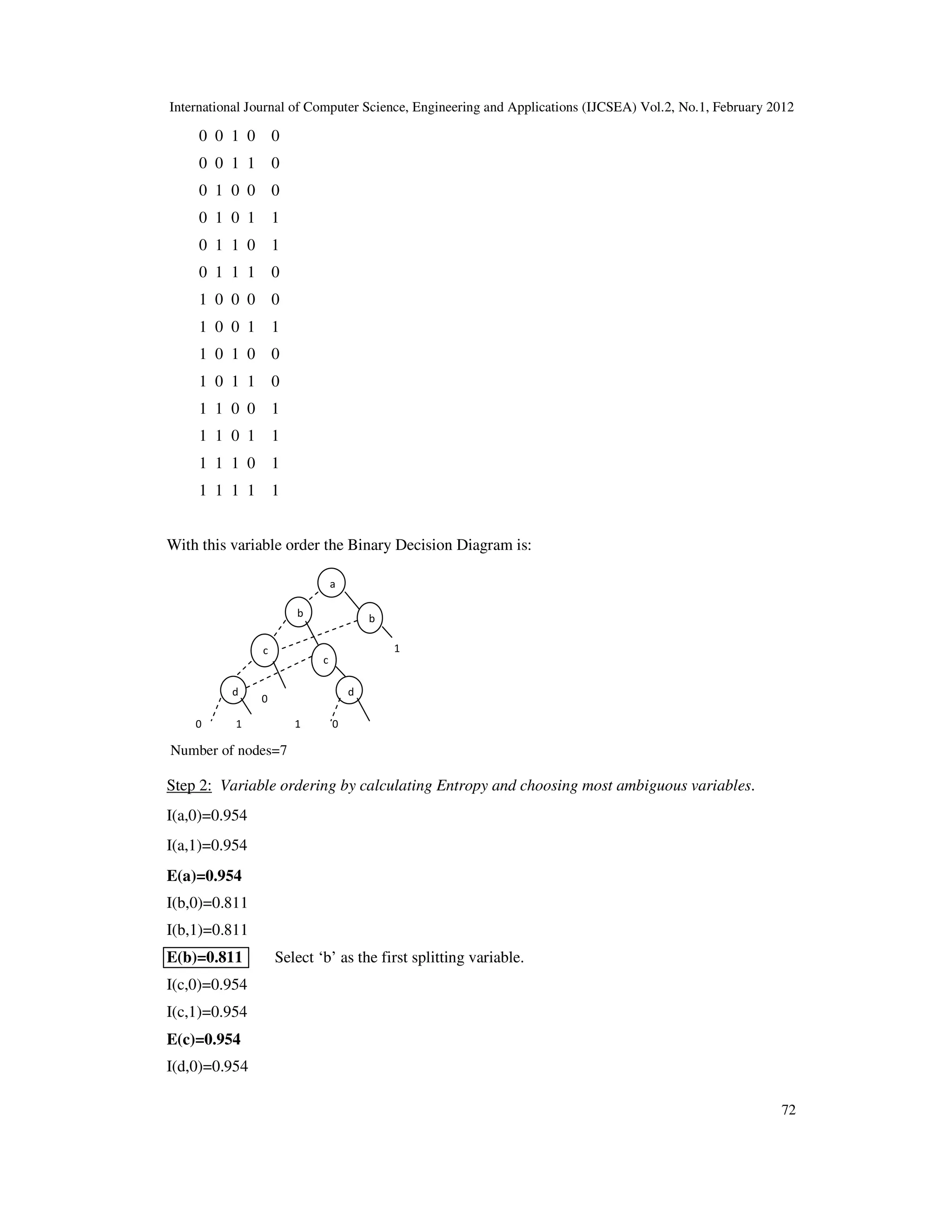
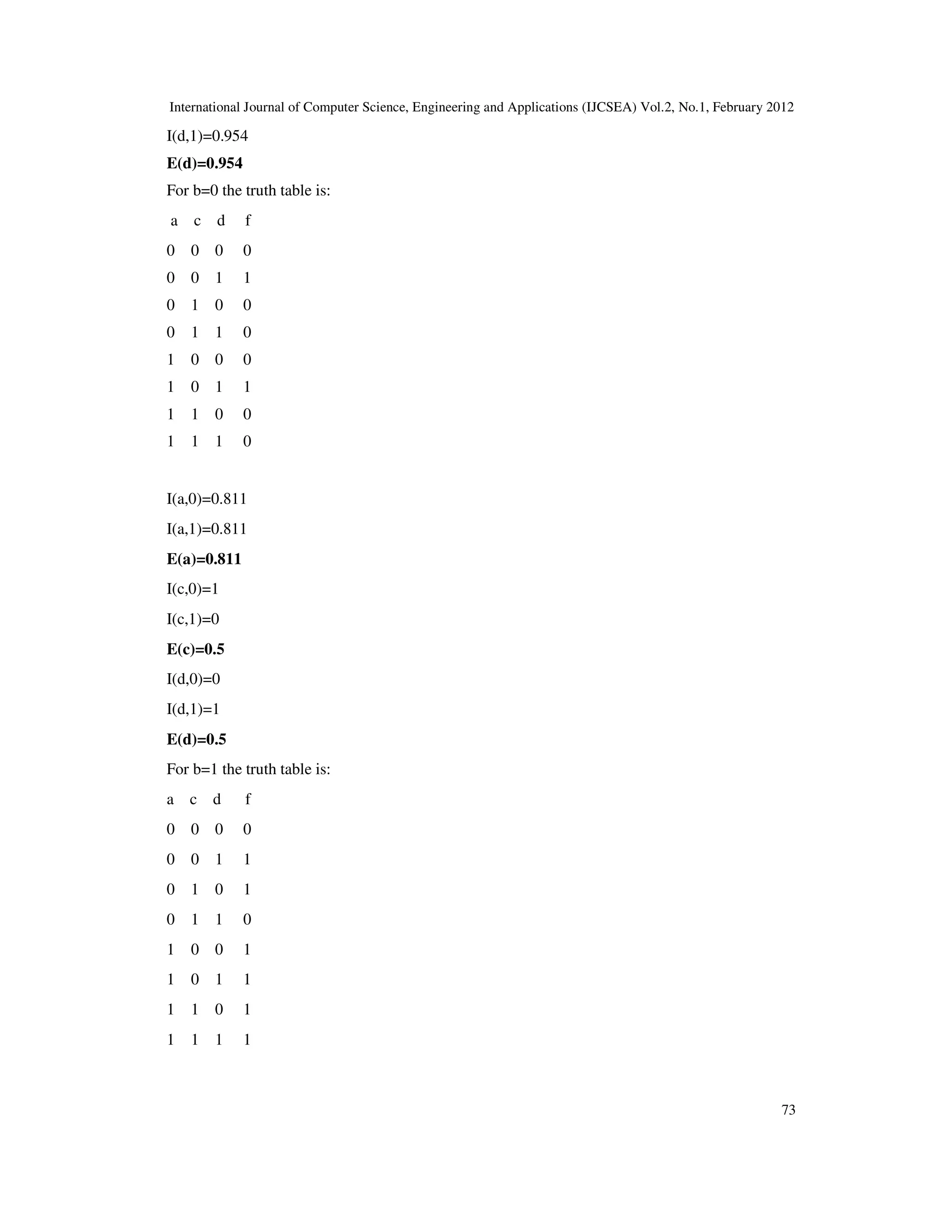
4. ILLUSTRATION WITH AN EXPLANATION
f(a,b,c,d)=∑(1,5,6,9,12,13,14,15)
Step1: Given the truth table.
a b c d f
0 0 0 0 0
0 0 0 1 1](https://image.slidesharecdn.com/2112ijcsea07-180627112100/75/ON-AN-OPTIMIZATION-TECHNIQUE-USING-BINARY-DECISION-DIAGRAM-5-2048.jpg)


![International Journal of Computer Science, Engineering and Applications (IJCSEA) Vol.2, No.1, February 2012
79
REFERENCES
[1] Sensarma D., Banerjee S., Basuli K., Naskar S., & Sarma, S. S. (2011) “Minimizing Boolean Sum of
Products Functions Using Binary Decision Diagram”, The Second International Conference on
Computer Science and Information Technology , Vol. 86, Part III, pp 36-48.
[2] Congguang Yang,Maciej Ciesielski.”BDD-BASED LOGIC OPTIMIZATION SYSTEM”.IEEE
transactions on computer aided design of integrated circuits and systems, Vol. 21, No.7, pp. – 866 -
876, July 2002.
[3] Denis V. Popel.”TOWARDS EFFICIENT CALCULATION OF INFORMATIONMEASURES FOR
REORDERING OF BINARY DECISION DIAGRAMS ”. Computing Research Repository - CORR
, vol. cs.AR/0207, 2002.
[4] Donald E. Knuth,”The Art of Computer Programming”, Volume 4.
[5] Gitanjali M. Swamy.”An Exact Logic Minimizer Using Implicit Binary Decision Diagram Based
Methods”. ICCAD '94 Proceedings of the 1994 IEEE/ACM international conference on Computer-
aided design.1994.
[6] Gorschwin Fey, Rolf Drechsler.”UTILIZING BDDS FOR DISJOINT SOP MINIMIZATION”. 45th
IEEE International Midwest Symposium on Circuits and Systems,2002.
[7] Günther R. Raidl et al.(Eds.).”Applications of evolutionary computing: EvoWorkshops 2004:
EvoBIO,EvoCOMNET,EvoHOT,EvoIASP,EvoMUSART,andEvoSTOC,Coimbra,Portugal,April
2004,Proceedings”.
[8] Henrik Reif Andersen. “An Introduction to Binary Decision Diagrams”. Lecture Notes (Technical
University of Denmark, October 1997).
[9] Jawhar Jain,James Bitner,Dinos Moundanos,Jacob A. Abraham,Donald S. Fussell.”A new scheme to
compute variable orders for binary decision diagrams”. VLSI, 1994. Design Automation of High
Performance VLSI Systems. GLSV '94, Proceedings., Fourth Great Lakes Symposium,pp. 105 – 108,
4-5 Mar 1994.
[10] M.Hilgemeier, N.Drechsler, and R.Drechsler.“Minimizing the number of one-paths in BDDs by an
evolutionary algorithm”. In Congress on Evolutionary Computation, 2003.
[11] Masoud Nosrati,Mehdi Hariri."An Algorithm for Minimizing of Boolean Functions Based on Graph
DS".World Applied Programming,Vol (1),No (3),August 2011.209-214.
[12] Olivier Coudert.”On solving Covering Problems”. in Proc. of 33rd DAC, Las Vegas, June 1996.
[13] Robert King Brayton. “Logic minimization algorithms for VLSI synthesis”.
[14] R.E. Bryant. “Graph-based algorithms for Boolean function manipulation”. IEEE Transactions on
Computers, C-35-8, pp.677-691, August, 1986.
[15] RANDAL E, BRYANT. “Symbolic Boolean Manipulation with Ordered Binary-Decision
Diagrams”. ACM Computing Surveys,1992.
[16] R.E. Bryant. “Binary decision diagrams and beyond: Enabeling techniques for formal verification”.In
Int’l Conf. on CAD, pages 236–243, 1995.
[17] Banerjee S., Sensarma D., Basuli K., Naskar S. & Sarma S. S. (2011) “The Reconstruction
Conjecture”, The Second International Conference on Computer Science and Information
Technology, Vol. 86, Part III, pp 17-25.
[18] R. Drechsler and B. Becker.”Binary Decision Diagrams – Theory and Implementation”. Kluwer
Academic Publishers, 1998.
[19] ZVI KOHAVI, Switching and Finite Automata Theory.
Authors
Debajit Sensarma
M. Sc. Computer Science
Subhashis Banerjee
M.Sc. Computer Science](https://image.slidesharecdn.com/2112ijcsea07-180627112100/75/ON-AN-OPTIMIZATION-TECHNIQUE-USING-BINARY-DECISION-DIAGRAM-13-2048.jpg)


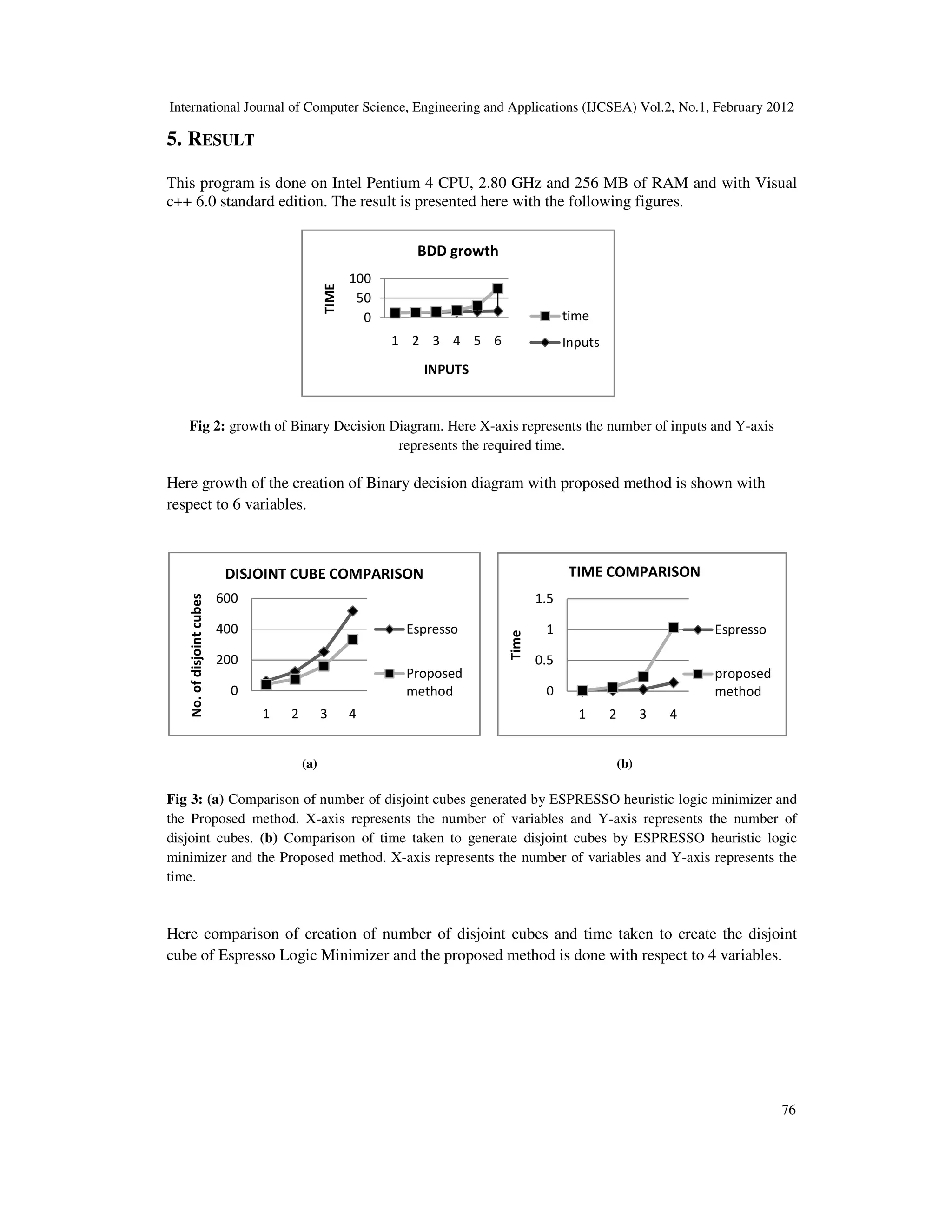
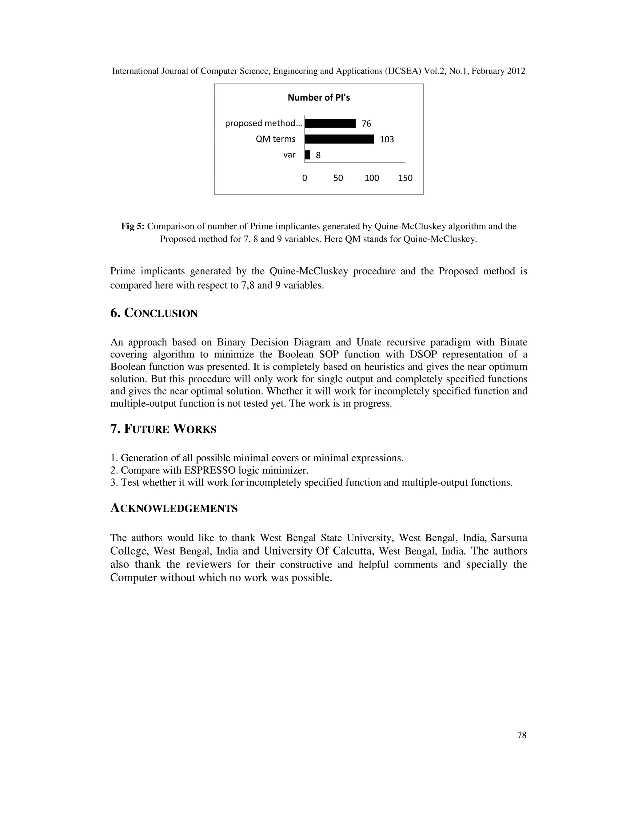
This document discusses an optimization technique for minimizing Boolean sum of products using Binary Decision Diagrams (BDDs). It highlights the speed and efficiency of the method, which leverages a symbolic representation to handle large problem instances, while stressing the importance of variable ordering in optimizing BDDs. Experimental results indicate that this technique performs comparably or better than other existing minimization approaches.