The document outlines a comprehensive facilities planning project focused on the production of c-clamps at a new factory in Burg El-Arab. It details the tasks involved, including product design, machine requirements, production area layout, employee needs, and material handling, using various charts and tables for clarity. Additionally, it justifies the selection of a product layout to optimize efficiency and effectiveness in production.
![13
3. TASK 3
REQUIRED:
a. State the name of departments in the production area
b. Select an appropriate layout [product layout, process layout, or cellular layout] and
c. justify your selection
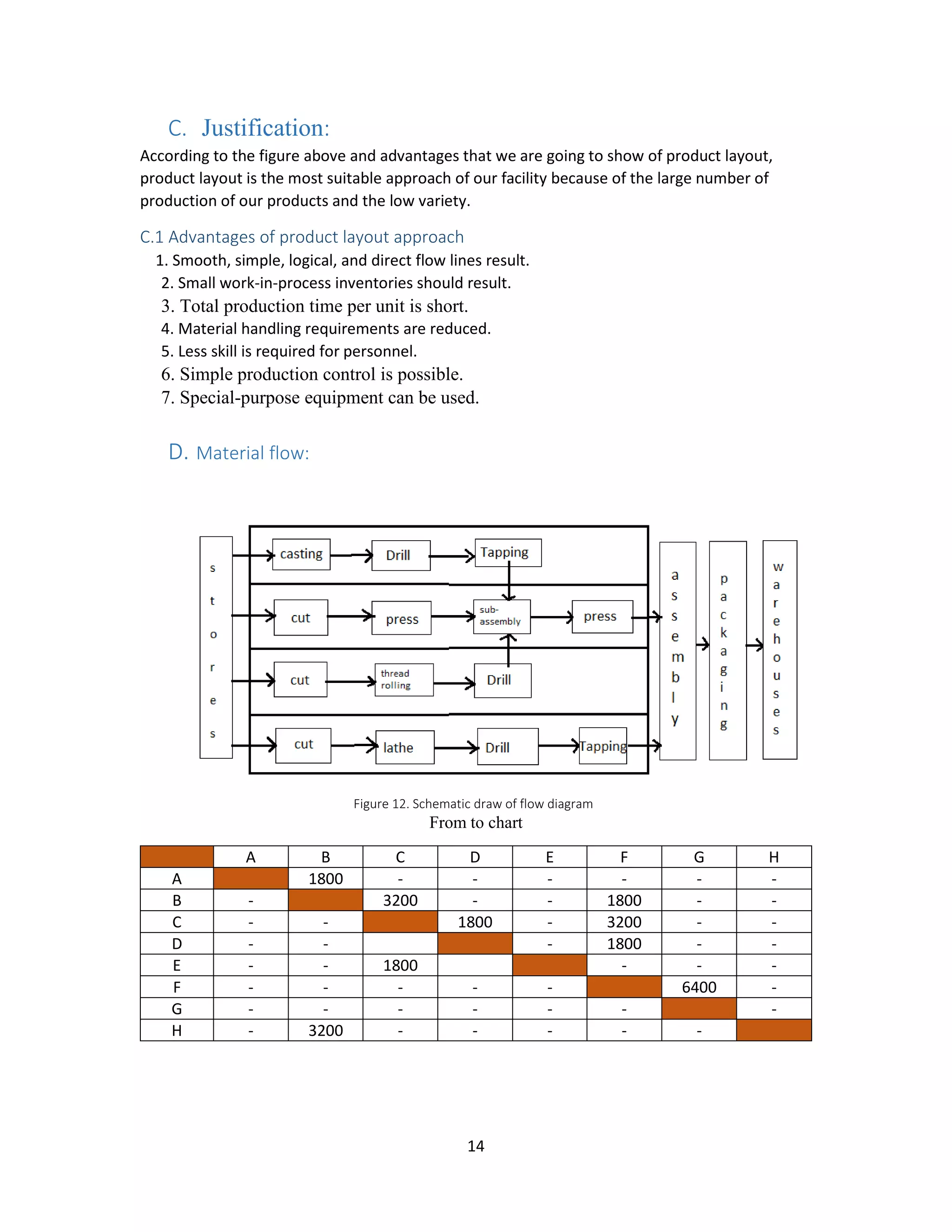
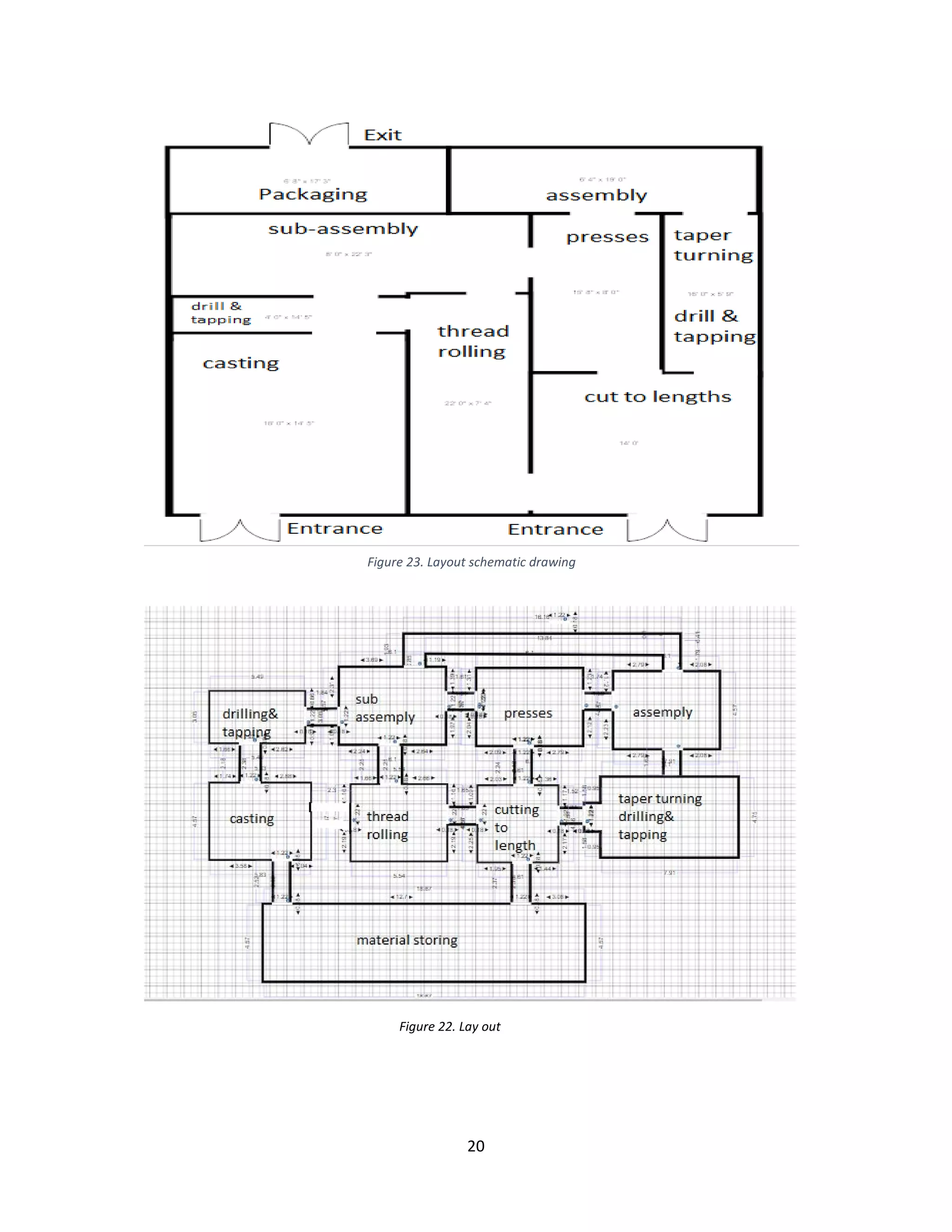
d. Draw an schematic diagram showing the material flow within the area (from stores
and
e. ending with warehouse)
f. Draw the production area layout
g. Calculate the required production area
A. List of departments in production area
• Casting department
• Forming department
• Machining department
• Assembly department
• Packaging department
B. Layout selection
We are going to select product layout
Figure 11. Volume-variety layout classification](https://image.slidesharecdn.com/finalreport2-190707170212/75/CClamp-Facility-Design-Project-17-2048.jpg)