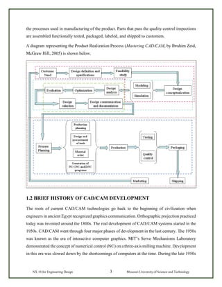
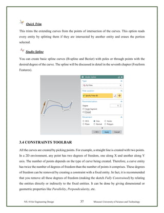
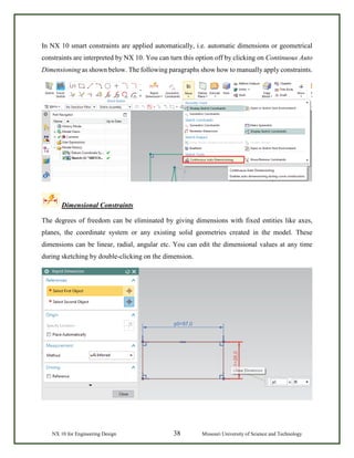
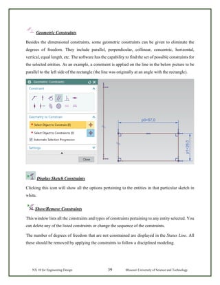
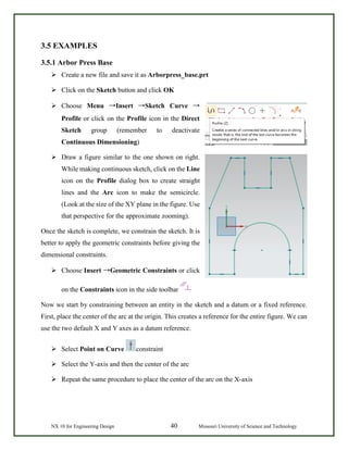
SlideShare a Scribd company logo
1 of 207
Download to read offline
NX 10 for Engineering Design
By
Ming C. Leu
Amir Ghazanfari
Krishna Kolan
Department of Mechanical and Aerospace Engineering
Contents
FOREWORD............................................................................................................1
CHAPTER 1 – INTRODUCTION.........................................................................2
1.1 Product Realization Process..................................................................................................2
1.2 Brief History of CAD/CAM Development...........................................................................3
1.3 Definition of CAD/CAM/CAE .............................................................................................5
1.3.1 Computer Aided Design – CAD .................................................................................. 5
1.3.2 Computer Aided Manufacturing – CAM ..................................................................... 5
1.3.3 Computer Aided Engineering – CAE........................................................................... 5
1.4. Scope of This Tutorial..........................................................................................................6
CHAPTER 2 – GETTING STARTED ..................................................................8
2.1 Starting an NX 10 Session and Opening Files......................................................................8
2.1.1 Start an NX 10 Session................................................................................................. 8
2.1.2 Open a New File........................................................................................................... 9
2.1.3 Open a Part File.......................................................................................................... 11
2.2 Printing, Saving and Closing Files......................................................................................12
2.2.1 Print an NX 10 Image................................................................................................. 12
2.2.2 Save Part Files............................................................................................................ 12
2.2.3 Close Part Files........................................................................................................... 13
2.2.4 Exit an NX 10 Session ............................................................................................... 14
2.3 NX 10 Interface...................................................................................................................14
2.3.1 Mouse Functionality................................................................................................... 14
2.3.2 NX 10 Gateway.......................................................................................................... 17
2.3.3 Geometry Selection.................................................................................................... 21
2.3.4 User Preferences......................................................................................................... 22
2.3.5 Applications ............................................................................................................... 25
2.4 Layers..................................................................................................................................26
2.4.1 Layer Control ............................................................................................................. 26
2.4.2 Commands in Layers.................................................................................................. 27
2.5 Coordinate Systems.............................................................................................................29
2.5.1 Absolute Coordinate System...................................................................................... 29
2.5.2 Work Coordinate System ........................................................................................... 29
2.5.3 Moving the WCS........................................................................................................ 29
2.6 Toolbars ..............................................................................................................................30
CHAPTER 3 – TWO DIMENSIONAL SKETCHING......................................33
3.1 Overview.............................................................................................................................33
3.2 Sketching Environment.......................................................................................................34
3.3 Sketch Curve Toolbar .........................................................................................................35
3.4 Constraints Toolbar.............................................................................................................37
3.5 Examples.............................................................................................................................40
3.5.1 Arbor Press Base ........................................................................................................ 40
3.5.2 Impeller Lower Casing............................................................................................... 44
3.5.3 Impeller ...................................................................................................................... 48
CHAPTER 4 – THREE DIMENSIONAL MODELING...................................50
4.1 Types of Features................................................................................................................50
4.1.1 Primitives ................................................................................................................... 51
4.1.2 Reference Features ..................................................................................................... 51
4.1.3 Swept Features ........................................................................................................... 52
4.1.4 Remove Features........................................................................................................ 53
4.1.5 Extract Features.......................................................................................................... 53
4.1.6 User-Defined features ................................................................................................ 54
4.2 Primitives ............................................................................................................................54
4.2.1 Model a Block ............................................................................................................ 54
4.2.2 Model a Shaft ............................................................................................................. 56
4.3 Reference Features..............................................................................................................58
4.3.1 Datum Plane ............................................................................................................... 58
4.3.2 Datum Axis ................................................................................................................ 60
4.4 Swept Features ....................................................................................................................61
4.5 Remove Features.................................................................................................................65
4.5.1 General Hole .............................................................................................................. 66
4.5.2 Pocket......................................................................................................................... 68
4.5.3 Slot ............................................................................................................................. 68
4.5.4 Groove........................................................................................................................ 68
4.6 Feature Operations ..............................................................................................................69
4.6.1 Edge Blend ................................................................................................................. 69
4.6.2 Chamfer...................................................................................................................... 69
4.6.3 Thread......................................................................................................................... 70
4.6.4 Trim Body .................................................................................................................. 71
4.6.5 Split Body................................................................................................................... 71
4.6.6 Mirror ......................................................................................................................... 71
4.6.7 Pattern......................................................................................................................... 72
4.6.8 Boolean Operations.................................................................................................... 73
4.6.9 Move........................................................................................................................... 73
4.7 Examples.............................................................................................................................75
4.7.1 Hexagonal Screw........................................................................................................ 75
4.7.2 Hexagonal Nut............................................................................................................ 78
4.7.3 L-Bar .......................................................................................................................... 81
4.7.4 Rack............................................................................................................................ 85
4.7.5 Impeller ...................................................................................................................... 89
4.8 Standard Parts Library.........................................................................................................92
4.9 Synchronous Technology....................................................................................................93
4.10 Exercises ...........................................................................................................................96
4.10.1 Circular Base............................................................................................................ 96
4.10.2 Impeller Upper Casing ............................................................................................. 96
4.10.3 Die-Cavity................................................................................................................ 97
CHAPTER 5 – DRAFTING..................................................................................99
5.1 Overview.............................................................................................................................99
5.2 Creating a Drafting............................................................................................................100
5.3 Dimensioning....................................................................................................................105
5.4 Sectional View ..................................................................................................................108
5.5 Product and Manufacturing Information...........................................................................109
5.6 Example.............................................................................................................................112
5.7 Exercise.............................................................................................................................116
CHAPTER 6 – ASSEMBLY MODELING .......................................................117
6.1 Terminology......................................................................................................................117
6.2 Assembling Approaches....................................................................................................118
6.2.1 Top-Down Approach................................................................................................ 118
6.2.2 Bottom-Up Approach............................................................................................... 118
6.2.3 Mixing and Matching............................................................................................... 119
6.3 Assembly Navigator..........................................................................................................119
6.4 Mating Constraints............................................................................................................120
6.5 Example.............................................................................................................................120
6.5.1 Starting an Assembly ............................................................................................... 121
6.5.2 Adding Components and Constraints....................................................................... 124
6.5.3 Exploded View......................................................................................................... 132
6.6 Exercise.............................................................................................................................135
CHAPTER 7 – FREEFORMING ......................................................................137
7.1 Overview...........................................................................................................................137
7.1.1 Creating Freeform Features from Points.................................................................. 138
7.1.2 Creating Freeform Features from Section Strings.................................................... 138
7.1.3 Creating Freeform Features from Faces................................................................... 139
7.2 FreeForm Feature Modeling .............................................................................................139
7.2.1 Modeling with Points ............................................................................................... 140
7.2.2 Modeling with a Point Cloud ................................................................................... 141
7.2.3 Modeling with Curves.............................................................................................. 143
7.2.4 Modeling with Curves and Faces............................................................................. 144
7.3 Exercise.............................................................................................................................146
CHAPTER 8 – FINITE ELEMENT ANALYSIS.............................................147
8.1 Overview...........................................................................................................................147
8.1.1 Element Shapes and Nodes ...................................................................................... 147
8.1.2 Solution Steps........................................................................................................... 149
8.1.3 Simulation Navigator ............................................................................................... 150
8.2 Scenario Creation..............................................................................................................150
8.3 Material Properties............................................................................................................153
8.4 Meshing.............................................................................................................................155
8.5 Loads.................................................................................................................................156
8.6 Boundary Conditions ........................................................................................................157
8.7 Result and Simulation .......................................................................................................158
8.7.1 Solving the Scenario................................................................................................. 158
8.7.2 FEA Result ............................................................................................................... 159
8.7.3 Simulation and Animation ....................................................................................... 162
8.8 Exercise.............................................................................................................................164
CHAPTER 9 – MANUFACTURING ................................................................165
9.1 Getting Started ..................................................................................................................165
9.1.1 Creation of a Blank .................................................................................................. 165
9.1.2 Setting Machining Environment .............................................................................. 167
9.1.3 Operation Navigator................................................................................................. 168
9.1.4 Machine Coordinate System (MCS) ........................................................................ 169
9.1.5 Geometry Definition ................................................................................................ 169
9.2 Creating Operation............................................................................................................170
9.2.1 Creating a New Operation........................................................................................ 170
9.2.2 Tool Creation and Selection..................................................................................... 171
9.2.3 Tool Path Settings .................................................................................................... 174
9.2.4 Step Over and Scallop Height .................................................................................. 175
9.2.5 Depth Per Cut........................................................................................................... 176
9.2.6 Cutting Parameters ................................................................................................... 176
9.2.7 Avoidance................................................................................................................. 177
9.2.8 Speeds and Feeds ..................................................................................................... 178
9.3 Program Generation and Verification...............................................................................180
9.3.1 Generating Program ................................................................................................. 180
9.3.2 Tool Path Display..................................................................................................... 180
9.3.3 Tool Path Simulation................................................................................................ 181
9.3.4 Gouge Check............................................................................................................ 183
9.4 Operation Methods............................................................................................................184
9.4.1 Roughing.................................................................................................................. 184
9.4.2 Semi-Finishing ......................................................................................................... 184
9.4.3 Finishing Profile....................................................................................................... 187
9.4.4 Finishing Contour Surface ....................................................................................... 191
9.4.5 Flooring.................................................................................................................... 195
9.5 Post Processing .................................................................................................................197
9.5.1 Creating CLSF.......................................................................................................... 198
9.5.2 Post Processing......................................................................................................... 199
NX 10 for Engineering Design 1 Missouri University of Science and Technology
FOREWORD
NX is one of the world’s most advanced and tightly integrated CAD/CAM/CAE product
development solution. Spanning the entire range of product development, NX delivers immense
value to enterprises of all sizes. It simplifies complex product designs, thus speeding up the process
of introducing products to the market.
The NX software integrates knowledge-based principles, industrial design, geometric modeling,
advanced analysis, graphic simulation, and concurrent engineering. The software has powerful
hybrid modeling capabilities by integrating constraint-based feature modeling and explicit
geometric modeling. In addition to modeling standard geometry parts, it allows the user to design
complex free-form shapes such as airfoils and manifolds. It also merges solid and surface modeling
techniques into one powerful tool set.
This self-guiding tutorial provides a step-by-step approach for users to learn NX 10. It is intended
for those with no previous experience with NX. However, users of previous versions of NX may
also find this tutorial useful for them to learn the new user interfaces and functions. The user will
be guided from starting an NX 10 session to creating models and designs that have various
applications. Each chapter has components explained with the help of various dialog boxes and
screen images. These components are later used in the assembly modeling, machining and finite
element analysis. The files of components are also available online to download and use. We first
released the tutorial for Unigraphics 18 and later updated for NX 2 followed by the updates for
NX 3, NX 5, NX 7 and NX 9. This write-up further updates to NX 10.
Our previous efforts to prepare the NX self-guiding tutorial were funded by the National Science
Foundation’s Advanced Technological Education Program and by the Partners of the
Advancement of Collaborative Engineering Education (PACE) program.
If you have any questions or comments about this tutorial, please email Ming C. Leu at
mleu@mst.edu or Amir Ghazanfari at ag4nc@mst.edu. The models and all the versions of the
tutorial are available at http://web.mst.edu/~mleu.
NX 10 for Engineering Design 2 Missouri University of Science and Technology
CHAPTER 1 – INTRODUCTION
The modern manufacturing environment can be characterized by the paradigm of delivering
products of increasing variety, smaller batches and higher quality in the context of increasing
global competition. Industries cannot survive worldwide competition unless they introduce new
products with better quality, at lower costs and with shorter lead-time. There is intense
international competition and decreased availability of skilled labor. With dramatic changes in
computing power and wider availability of software tools for design and production, engineers are
now using Computer Aided Design (CAD), Computer Aided Manufacturing (CAM) and Computer
Aided Engineering (CAE) systems to automate their design and production processes. These
technologies are now used every day for sorts of different engineering tasks. Below is a brief
description of how CAD, CAM, and CAE technologies are being used during the product
realization process.
1.1 PRODUCT REALIZATION PROCESS
The product realization process can be roughly divided into two phases; design and manufacturing.
The design process starts with identification of new customer needs and design variables to be
improved, which are identified by the marketing personnel after getting feedback from the
customers. Once the relevant design information is gathered, design specifications are formulated.
A feasibility study is conducted with relevant design information and detailed design and analyses
are performed. The detailed design includes design conceptualization, prospective product
drawings, sketches and geometric modeling. Analysis includes stress analysis, interference
checking, kinematics analysis, mass property calculations and tolerance analysis, and design
optimization. The quality of the results obtained from these activities is directly related to the
quality of the analysis and the tools used for conducting the analysis.
The manufacturing process starts with the shop-floor activities beginning from production
planning, which uses the design process drawings and ends with the actual product. Process
planning includes activities like production planning, material procurement, and machine
selection. There are varied tasks like procurement of new tools, NC programming and quality
checks at various stages during the production process. Process planning includes planning for all
NX 10 for Engineering Design 3 Missouri University of Science and Technology
the processes used in manufacturing of the product. Parts that pass the quality control inspections
are assembled functionally tested, packaged, labeled, and shipped to customers.
A diagram representing the Product Realization Process (Mastering CAD/CAM, by Ibrahim Zeid,
McGraw Hill, 2005) is shown below.
1.2 BRIEF HISTORY OF CAD/CAM DEVELOPMENT
The roots of current CAD/CAM technologies go back to the beginning of civilization when
engineers in ancient Egypt recognized graphics communication. Orthographic projection practiced
today was invented around the 1800s. The real development of CAD/CAM systems started in the
1950s. CAD/CAM went through four major phases of development in the last century. The 1950s
was known as the era of interactive computer graphics. MIT’s Servo Mechanisms Laboratory
demonstrated the concept of numerical control (NC) on a three-axis milling machine. Development
in this era was slowed down by the shortcomings of computers at the time. During the late 1950s
NX 10 for Engineering Design 4 Missouri University of Science and Technology
the development of Automatically Programmed Tools (APT) began and General Motors explored
the potential of interactive graphics.
The 1960s was the most critical research period for interactive computer graphics. Ivan Sutherland
developed a sketchpad system, which demonstrated the possibility of creating drawings and
altercations of objects interactively on a cathode ray tube (CRT). The term CAD started to appear
with the word ‘design’ extending beyond basic drafting concepts. General Motors announced their
DAC-1 system and Bell Technologies introduced the GRAPHIC 1 remote display system.
During the 1970s, the research efforts of the previous decade in computer graphics had begun to
be fruitful, and potential of interactive computer graphics in improving productivity was realized
by industry, government and academia. The 1970s is characterized as the golden era for computer
drafting and the beginning of ad hoc instrumental design applications. National Computer
Graphics Association (NCGA) was formed and Initial Graphics Exchange Specification (IGES)
was initiated.
In the 1980s, new theories and algorithms evolved and integration of various elements of design
and manufacturing was developed. The major research and development focus was to expand
CAD/CAM systems beyond three-dimensional geometric designs and provide more engineering
applications.
The present day CAD/CAM development focuses on efficient and fast integration and automation
of various elements of design and manufacturing along with the development of new algorithms.
There are many commercial CAD/CAM packages available for direct usages that are user-friendly
and very proficient.
Below are some of the commercial packages in the present market.
• Solid Edge, AutoCAD and Mechanical Desktop are some low-end CAD software systems,
which are mainly used for 2D modeling and drawing.
• NX, Pro-E, CATIA and I-DEAS are high-end modeling and designing software systems
that are costlier but more powerful. These software systems also have computer aided
manufacturing and engineering analysis capabilities.
• ANSYS, ABAQUS, NASTRAN, and COMSOL are packages mainly used for analysis of
structures and fluids. Different software are used for different proposes.
NX 10 for Engineering Design 5 Missouri University of Science and Technology
• Geomagic and CollabCAD are some of the systems that focus on collaborative design,
enabling multiple users of the software to collaborate on computer-aided design over the
Internet.
1.3 DEFINITION OF CAD/CAM/CAE
Following are the definitions of some of the terms used in this tutorial.
1.3.1 Computer Aided Design – CAD
CAD is technology concerned with using computer systems to assist in the creation, modification,
analysis, and optimization of a design. Any computer program that embodies computer graphics
and an application program facilitating engineering functions in design process can be classified
as CAD software.
The most basic role of CAD is to define the geometry of design – a mechanical part, a product
assembly, an architectural structure, an electronic circuit, a building layout, etc. The greatest
benefits of CAD systems are that they can save considerable time and reduce errors caused by
otherwise having to redefine the geometry of the design from scratch every time it is needed.
1.3.2 Computer Aided Manufacturing – CAM
CAM technology involves computer systems that plan, manage, and control the manufacturing
operations through computer interface with the plant’s production resources.
One of the most important areas of CAM is numerical control (NC). This is the technique of using
programmed instructions to control a machine tool, which cuts, mills, grinds, punches or turns raw
stock into a finished part. Another significant CAM function is in the programming of robots.
Process planning is also a target of computer automation.
1.3.3 Computer Aided Engineering – CAE
CAE technology uses a computer system to analyze the functions of a CAD-created product,
allowing designers to simulate and study how the product will behave so that the design can be
refined and optimized.
CAE tools are available for a number of different types of analyses. For example, kinematic
analysis programs can be used to determine motion paths and linkage velocities in mechanisms.
Dynamic analysis programs can be used to determine loads and displacements in complex
NX 10 for Engineering Design 6 Missouri University of Science and Technology
assemblies such as automobiles. One of the most popular methods of analyses is using a Finite
Element Method (FEM). This approach can be used to determine stress, deformation, heat transfer,
magnetic field distribution, fluid flow, and other continuous field problems that are often too tough
to solve with any other approach.
1.4. SCOPE OF THIS TUTORIAL
This tutorial is written for students and engineers who are interested in learning how to use NX 10
for designing mechanical components and assemblies. Learning to use this software will also be
valuable for learning how to use other CAD systems such as PRO-E and CATIA.
This tutorial provides a step-by-step approach for learning NX 10.
Chapter 2 includes the NX 10 essentials from starting a session to getting familiar with the NX
10 layout by practicing basic functions such as Print, Save, and Exit. It also gives a brief description
of the Coordinate System, Layers, various toolboxes and other important commands, which will
be used in later chapters.
Chapter 3 presents the concept of sketching. It describes how to create sketches and to give
geometric and dimensional constraints. This chapter is very important since present-day
components are very complex in geometry and difficult to model with only basic features.
The actual designing and modeling of parts begins with chapter 4. It describes different features
such as reference features, swept features and primitive features and how these features are used
to create designs. Various kinds of feature operations are performed on features.
You will learn how to create a drawing from a part model in chapter 5. In this chapter, we
demonstrate how to create a drawing by adding views, dimensioning the part drawings, and
modifying various attributes in the drawing such as text size, arrow size and tolerance.
Chapter 6 teaches the concepts of Assembly Modeling and its terminologies. It describes Top-
Down modeling and Bottom-Up modeling. We will use Bottom-Up modeling to assemble
components into a product.
Chapter 7 introduces free-form modeling. The method of modeling curves and smooth surfaces
will be demonstrated.
NX 10 for Engineering Design 7 Missouri University of Science and Technology
Chapter 8 is capsulated into a brief introduction to Design Simulations available in NX 10 for the
Finite Element Analysis.
Chapter 9 will be a real-time experience of implementing a designed model into a manufacturing
environment for machining. This chapter deals with generation, verification and simulation of Tool
Path to create CNC (Computer Numerical Codes) to produce the designed parts from multiple axes
and even advanced CNC machines.
The examples and exercise problems used in each chapter are so designed that they will be finally
assembled in the chapter. Due to this distinctive feature, you should save all the models that you
have generated in each chapter.
NX 10 for Engineering Design 8 Missouri University of Science and Technology
CHAPTER 2 – GETTING STARTED
We begin with starting of an NX 10 session. This chapter will provide the basics required to use
any CAD/CAM package. You will learn the preliminary steps to start, to understand and to use the
NX 10 package for modeling, drafting, etc. It contains five sub-sections a) Opening an NX 10
session, b) Printing, saving, and closing part files, c) getting acquainted with the NX 10 user
interface d) Using layers and e) Understanding important commands and dialogs.
2.1 STARTING AN NX 10 SESSION AND OPENING FILES
2.1.1 Start an NX 10 Session
 From the Windows desktop screen, click on Start →All Programs →Siemens NX 10 →
NX 10
NX 10 for Engineering Design 9 Missouri University of Science and Technology
The main NX 10 Screen will open. This is the Gateway for the NX 10 software. The NX 10 blank
screen looks like the figure shown below. There will be several tips displayed on the screen about
the special features of the current version. The Gateway also has the Standard Toolbar that will
allow you to create a new file or open an existing file. On the left side of the Gateway screen, there
is a toolbar called the Resource Bar that has menus related to different modules and the ability to
define and change the Role of the software, view History of the software use and so on. This will
be explained in detail later in this chapter.
2.1.2 Open a New File
Let’s begin by learning how to open a new part file in NX 10. To create a new file there are three
options.
 Click on the New button on top of the screen
OR
NX 10 for Engineering Design 10 Missouri University of Science and Technology
 Go through the File drop-down menu at the top-left of the screen and click New
OR
 Press <Ctrl> + N
This will open a new session, asking for the type, name and location of the new file to be created.
There are numerous types of files in NX 10 to select from the Templates dialogue box located at
the center of the window. The properties of the selected file are displayed below the Preview on
the right side. Since we want to work in the modeling environment and create new parts, only
specify the units (inches or millimeters) of the working environment and the name and location of
the file. The default unit is millimeters.
 Enter an appropriate name and location for the file and click OK
NX 10 for Engineering Design 11 Missouri University of Science and Technology
2.1.3 Open a Part File
There are several ways to open an existing file.
 Click on the Open or Open a Recent Part button on top of the screen
OR
 Go through the File drop-down menu at the top-left of the screen and click Open
OR
 Press <Ctrl> + O
The Open Part File dialog will appear. You can see the preview of the files on the right side of the
window. You can disable the Preview by un-clicking the box in front of the Preview button.
 Click Cancel to exit the window
NX 10 for Engineering Design 12 Missouri University of Science and Technology
2.2 PRINTING, SAVING AND CLOSING FILES
2.2.1 Print an NX 10 Image
To print an image from the current display,
 Click File →Print
The following figure shows the Print dialog box. Here,
you can choose the printer to use or specify the number
of copies to be printed, size of the paper and so on.
You can also select the scale for all the three
dimensions. You can also choose the method of
printing, i.e. wireframe, solid model by clicking on the
Output drop down-menu as shown in the Figure on right
side
 Click Cancel to exit the window
2.2.2 Save Part Files
It is imperative that you save your work frequently. If
for some reasons, NX 10 shuts down and the part is not
saved, all the work will be lost. To save the part files,
 Click File →Save
There are five options to save a file:
Save: This option will save the part on screen with the
same name as given before while creating the part file.
Save Work Part Only: This option will only save the
active part on the screen.
Save As: This option allows you to save the part on screen using a different name and/or type. The
default type is .prt. However, you can save your file as IGES (.igs), STEP 203 (.stp), STEP 214
(.step), AutoCAD DXF (.dxf), AutoCAD DWG (.dwg), CATIA Model (.model) and CATIA V5
(.catpart).
Save All: This option will save all the opened part files with their existing names.
NX 10 for Engineering Design 13 Missouri University of Science and Technology
Save Bookmark: This option will save a screenshot and context of the present model on the screen
as a .JPEG file and bookmarks.
2.2.3 Close Part Files
You can choose to close the parts that are
visible on screen by
 Click File →Close
If you close a file, the file will be cleared from
the working memory and any changes that are
not saved will be lost. Therefore, remember
to select Save and Close, Save As and Close,
Save All and Close or Save All and Exit. In
case of the first three options, the parts that
are selected or all parts will be closed but the
NX 10 session keeps on running.
NX 10 for Engineering Design 14 Missouri University of Science and Technology
2.2.4 Exit an NX 10 Session
 Click File →Exit
If you have files open and have made changes to them without saving, the message will ask you if
you really want to exit.
 Select No, save the files and then Exit
2.3 NX 10 INTERFACE
The user interface of NX 10 is made very simple through the use of different icons. Most of the
commands can be executed by navigating the mouse around the screen and clicking on the icons.
The keyboard entries are mostly limited to entering values and naming files.
2.3.1 Mouse Functionality
2.3.1.1 Left Mouse Button (MB1)
The left mouse button, named Mouse Button 1 (MB1) in NX, is used for Selection of icons, menus,
and other entities on the graphic screen. Double clicking MB1 on any feature will automatically
open the Edit Dialog box. Clicking MB1 on an object enables the user to have quick access to
several options shown below. These options will be discussed in next chapters.
NX 10 for Engineering Design 15 Missouri University of Science and Technology
2.3.1.2 Middle Mouse Button (MB2)
The middle mouse button (MB2) or the scroll button is used to Rotate the object by pressing,
holding and dragging. The model can also be rotated about a single axis. To rotate about the axis
horizontal to the screen, place the mouse pointer near the right edge of the graphic screen and
rotate. Similarly, for the vertical axis and the axis perpendicular to the screen, click at the bottom
edge and top edge of the screen respectively and rotate. If you keep pressing the MB2 at the same
position for a couple of seconds, it will fix the point of rotation (an orange circle symbol appears)
and you can drag around the object to view.
If it is a scroll button, the object can be zoomed in and out by scrolling. Clicking the MB2 will
also execute the OK command if any pop-up window or dialog box is open.
2.3.1.3 Right Mouse Button (MB3)
MB3 or Right Mouse Button is used to
access the user interface pop-up
menus. You can access the subsequent
options that pop up depending on the
selection mode and Application. The
figure shown below is in Sketch
Application. Clicking on MB3 when a
feature is selected will give the options
related to that feature (Object/Action
Menu).
NX 10 for Engineering Design 16 Missouri University of Science and Technology
Clicking MB3 and holding the button will display a set of icons around the feature.
These icons feature the possible commands that can be applied to the feature.
2.3.1.4 Combination of Buttons
Zoom In /Out:
 Press and hold both MB1 and MB2 simultaneously and drag
OR
 Press and hold <Ctrl> button on the keyboard and then press and drag the MB2
OR
Pan:
 Press and hold both the MB2 and MB3 simultaneously and drag
OR
 Press and hold <Shift> button on the keyboard and press and drag the MB2
Shortcut to menus:
 Press and hold <Ctrl> + <Shift> and MB1, MB2 and MB3 to see shortcuts to Feature,
Direct Sketch, and Synchronous Modeling groups, respectively
NX 10 for Engineering Design 17 Missouri University of Science and Technology
2.3.2 NX 10 Gateway
The following figure shows the typical layout of the NX 10 window when a file is opened. This is
the Gateway of NX 10 from where you can select any module to work on such as modeling,
manufacturing, etc. It has to be noted that these toolbars may not be exactly on the same position
of the screen as shown below. The toolbars can be placed at any location or position on the screen.
Look out for the same set of icons.
2.3.2.1 Ribbon Bar
The ribbon bar interface gives the user the ability to access the different commands easily without
reducing the graphics window area. Commands are organized in ribbon bars under different tabs
and groups for easy recognition and accessibility.
Resource Bar
Cue Line
Tabs
Graphic Window
Ribbon Bar
Top-border
Groups
Quick Access Toolbar
Command Finder
NX 10 for Engineering Design 18 Missouri University of Science and Technology
For example in the ribbon bar shown in the figure above, we have home, curve, etc. tabs. In the
home tab, we have direct sketch, feature, synchronous modeling and surface groups. And in each
group, we have a set of featured commands.
2.3.2.2 Quick Access Toolbar
The quick access toolbar has most commonly used buttons (save, undo, redo, cut, copy, paste and
recent commands) to expedite the modeling process. You may easily customize these buttons as
shown in the figure below.
2.3.2.3 Command Finder
If you do not know where to find a command, use Command Finder. Let’s say we have forgotten
where the Styled Sweep is.
 Type sweep in the Command Finder
 Hover the mouse over Styled Sweep
 NX will show you the path to the command: Menu →Insert →Sweep →Styled Sweep
OR
NX 10 for Engineering Design 19 Missouri University of Science and Technology
 Type sweep in the Command Finder
 Click on Styled Sweep in the Command Finder window
2.3.2.4 Top-border
The most important button in the top-border is the menu button. Most of the features and functions
of the software are available in the menu. The Selection Bar displays the selection options. These
options include the Filters, Components/Assembly, and Snap Points for selecting features. Most
common buttons in the View tab are also displayed in the Top-border.
2.3.2.5 Resource Bar
The Resource Bar features icons for a number of pages in one place using very little user interface
space. NX 10 places all navigator windows (Assembly, Constraint and Part) in the Resource Bar,
as well as the Reuse Library, HD3D Tools, Web Browser, History Palette, Process Studio,
NX 10 for Engineering Design 20 Missouri University of Science and Technology
Manufacturing Wizards, Roles and System Scenes. Two of the most important widows are
explained below.
Part Navigator
 Click on the Part Navigator icon, the third
icon from the top on the Resource bar
The Part Navigator provides a visual representation
of the parent-child relationships of features in the
work part in a separate window in a tree type format.
It shows all the primitives, entities used during
modeling. It allows you to perform various editing
actions on those features. For example, you can use
the Part Navigator to Suppress or Unsuppress the
features or change their parameters or positioning
dimensions. Removing the green tick mark will
‘Suppress’ the feature. The software will give a
warning if the parent child relationship is broken by
suppressing any particular feature.
The Part Navigator is available for all NX
applications and not just for modeling. However, you can only perform feature-editing operations
when you are in the Modeling module. Editing a feature in the Part Navigator will automatically
update the model. Feature editing will be discussed later.
History
 Click on the History icon, the seventh from the top on the Resource bar
The History Palette provides fast access to recently opened files or other palette entries. It can be
used to reload parts that have been recently worked on or to repeatedly add a small set of palette
items to a model.
The History Palette remembers the last palette options that were used and the state of the session
when it was closed. NX stores the palettes that were loaded into a session and restores them in the
next session. The system does not clean up the History Palette when parts are moved.
NX 10 for Engineering Design 21 Missouri University of Science and Technology
To re-use a part, drag and drop it from the History
Palette to the Graphics Window. To reload a part,
click on a saved session bookmark.
2.3.2.6 Cue Line
The Cue Line displays prompt messages that indicate
the next action that needs to be taken. To the right of
the Cue line, the Status Line is located which
displays messages about the current options or the
most recently completed function.
The Progress Meter is displayed in the Cue Line
when the system performs a time-consuming
operation such as loading a large assembly. The
meter shows the percentage of the operation that has
been completed. When the operation is finished, the
system displays the next appropriate cue.
2.3.3 Geometry Selection
You can filter the selection method, which facilitates
easy selection of the geometry in a close cluster. In
addition, you can perform any of the feature
operation options that NX 10 intelligently provides
depending on the selected entity. Selection of items can be based on the degree of the entity like,
selection of Geometric entities, Features and Components. The selection method can be opted by
choosing one of the icons in the Selection Toolbar.
2.3.3.1 Feature Selection
Clicking on any of the icons lets you select the features in the part file. It will not select the basic
entities like edges, faces etc. The features selected can also be applied to a part or an entire
assembly depending upon the requirement.
NX 10 for Engineering Design 22 Missouri University of Science and Technology
Besides that, the filtering of the features can be further narrowed down by
selecting one of the desired options in the drop-down menu as shown in the
figure. For example, selecting Curve will highlight only the curves in the
screen. The default is No Selection Filter.
2.3.3.2 General Object Selection
Navigate the mouse cursor closer to the entity until it is highlighted with a
magenta color and click the left mouse button to select any geometric entity,
feature, or component.
If you want to select an entity that is hidden behind the displayed geometry,
place the mouse cursor roughly close to that area on the screen such that the
cursor ball occupies a portion of the hidden geometry projected on the
screen. After a couple of seconds, the ball cursor turns into a plus symbol
as shown in the figure. Click the left mouse button (MB1) to get a Selection
Confirmation dialog box as shown in the
following figure below. This QuickPick
menu consists of the list of entities
captured within the ball of the cursor. The
entities are arranged in ascending order of
the degree of the entity. For example,
edges and vertices are assigned lower
numbers while solid faces are given
higher numbers. By moving the cursor on
the numbers displayed, NX 10 will
highlight the corresponding entity on the screen in a magenta color.
2.3.4 User Preferences
 Choose Preferences on the Menu button (located to top left of the main window) to find
the various options available
NX 10 for Engineering Design 23 Missouri University of Science and Technology
User Preferences are used to define the display parameters of
new objects, names, layouts, and views. You can set the layer,
color, font, and width of created objects. You can also design
layouts and views, control the display of object and view
names and borders, change the size of the selection ball,
specify the selection rectangle method, set chaining tolerance
and method, and design and activate a grid. Changes that you
make using the Preferences menu override any counterpart
customer defaults for the same functions.
2.3.4.1 User Interface
 Choose Preferences →User Interface to find the
options in the dialog box
The User Interface option customizes how NX works and
interacts to specifications you set. You can control the
location, size and visibility status of the main window,
graphics display, and information window. You can set the
number of decimal places (precision) that the system uses for
both input text fields and data displayed in the information
window. You can also specify a full or small dialog for file
selection. You can also set macro options and enable a
confirmation dialog for Undo operations.
• The Layout tab allows you to select the User Interface Environment
• The Touch tab lets you use touch screens
• The Options tab allows you, among others, to set the precision level (in the Information
Window)
• The Journal tab in the Tools allows you to use several programming languages
• The Macro tab in the Tools allows you to set the pause while displaying animation
NX 10 for Engineering Design 24 Missouri University of Science and Technology
2.3.4.2 Visualization
 Choose Preferences →Visualization to find the
options in the dialog box
This dialog box controls attributes that affect the display in
the graphics window. Some attributes are associated with
the part or with particular Views of the part. The settings for
these attributes are saved in the part file. For many of these
attributes, when a new part or a view is created, the setting
is initialized to the value specified in the Customer Defaults
file. Other attributes are associated with the session and
apply to all parts in the session. The settings of some of
these attributes are saved from session to session in the
registry. For some session attributes, the setting can be
initialized to the value specified by customer default, an
environment variable.
 Choose Preferences →Color Pallet to find the
options in the dialog box
NX 10 for Engineering Design 25 Missouri University of Science and Technology
 Click on Preferences →Background to get
another pop up Dialog box. You can change
your background color whatever you want
The background color refers to the color of the
background of the graphics window. NX supports
graduated backgrounds for all display modes. You can
select background colors for Shaded or Wireframe
displays. The background can be Plain or Graduated.
Valid options for all background colors are 0 to 255.
You can change and observe the Color and
Translucency of objects.
 Click Preferences →Object
This will pop up a dialog window Object Preferences.
You can also apply this setting to individual entities of
the solid. For example, you can click on any particular
surface of the solid and apply the Display settings.
2.3.5 Applications
Applications can be opened using the File option
located at the top left corner of the main window OR
the Applications tab above the Ribbon bar. You can
select the type of application you want to run. For
example, you can select Modeling, Drafting,
Assembly, and so on as shown in the figure. The default Application that starts when you open a
file or start a new file is Modeling. We will introduce some of these Application in the next
chapters.
NX 10 for Engineering Design 26 Missouri University of Science and Technology
2.4 LAYERS
Layers are used to store objects in a file, and work like containers to collect the objects in a
structured and consistent manner. Unlike simple visual tools like Show and Hide, Layers provide
a permanent way to organize and manage the visibility and selectability of objects in your file.
2.4.1 Layer Control
With NX 10, you can control whether objects are visible or selectable by using Layers. A Layer is
a system-defined attribute such as color, font, and width that all objects in NX 10 must have. There
are 256 usable layers in NX 10, one of which is always the Work Layer. Any of the 256 layers can
be assigned to one of four classifications of status.
• Work
• Selectable
• Visible Only
• Invisible
The Work Layer is the layer that objects are created ON and is
always visible and selectable while it remains the Work Layer.
Layer 1 is the default Work Layer when starting a new part file.
When the Work Layer is changed to another type of layer, the
previous Work Layer automatically becomes Selectable and can
then be assigned a status of Visible Only or Invisible.
The number of objects that can be on one layer is not limited. You
have the freedom to choose whichever layer you want to create
the object on and the status of that layer.
To assign a status to a layer or layers,
 Choose View →Layer Settings
However, it should be noted that the use of company standards in
regards to layers would be advantageous to maintain a consistency
between files.
NX 10 for Engineering Design 27 Missouri University of Science and Technology
2.4.2 Commands in Layers
We will follow simple steps to practice the commands in Layers. First, we will create two objects
(Solids) by the method as follows. The details of Solid Modeling will be discussed in the next
chapter. The solids that we draw here are only for practice in this chapter.
 Choose File →New
Name the file and choose a folder in which to save it. Make
sure you select the units to be millimeters in the drop-down
menu. Choose the file type as Model
 Choose Menu →Insert →Design Feature
→Cone
 Choose Diameter and Height under Type
 Click OK
 Right-click on the screen and choose Orient View
→Trimetric
 Right-click on the screen and choose Rendering
Style →Shaded
You will be able to see a solid cone similar to the picture
on right.
Now let us practice some Layer Commands.
 Choose View →Move to Layer
You will be asked to select an object
 Move the cursor on to the Cone and click on it so that it becomes highlighted
 Click OK
NX 10 for Engineering Design 28 Missouri University of Science and Technology
 In the Destination Layer or Category space at the top of the window, type 25 and Click
OK
The Cone has now gone to the 25th
layer. It can no longer be
seen in Layer 1.
 To see the Cone, click View →Layer Settings
 You can see that Layer 25 has the object whereas the
default Work Layer 1 has no objects.
The Cone will again be seen on the screen. Save the file as we
will be using it later in the tutorial.
NX 10 for Engineering Design 29 Missouri University of Science and Technology
2.5 COORDINATE SYSTEMS
There are different coordinate systems in NX. A three-axis symbol is used to identify the
coordinate system.
2.5.1 Absolute Coordinate System
The Absolute Coordinate System is the coordinate system from which
all objects are referenced. This is a fixed coordinate system and the
locations and orientations of every object in NX 10 modeling space are
related back to this system. The Absolute Coordinate System (or
Absolute CSYS) also provides a common frame of reference between
part files. An absolute position at X=1, Y=1, and Z=1 in one part file is
the same location in any other part file.
The View Triad on the bottom-left of the Graphics window is ONLY a visual
indicator that represents the ORIENTATION of the Absolute Coordinate System
of the model.
2.5.2 Work Coordinate System
The Work Coordinate System (WCS) is what you will use for construction when you want to
determine orientations and angles of features. The axes of the WCS are denoted XC, YC, and ZC.
(The “C” stands for “current”). It is
possible to have multiple coordinate
systems in a part file, but only one of them
can be the work coordinate system.
2.5.3 Moving the WCS
Here, you will learn how to translate and
rotate the WCS.
 Choose Menu →Format →WCS
2.5.3.1 Translate the WCS
This procedure will move the WCS origin
to any point you specify, but the
NX 10 for Engineering Design 30 Missouri University of Science and Technology
orientation (direction of the axes) of the WCS will remain the same.
 Choose Menu →Format →WCS →Origin
The Point Constructor dialog is displayed. You either can
specify a point from the drop down menu at the top of the
dialog box or enter the X-Y-Z coordinates in the XC, YC,
and ZC fields.
The majority of the work will be in relation to the Work
Coordinate System rather than the Absolute Coordinate
System. The default is the WCS.
2.5.3.2 Rotate the WCS
You can also rotate the WCS around one of its axes.
 Choose Menu → Format →WCS →Rotate
The dialog shows six different ways to rotate the WCS
around an axis. These rotation procedures follow the right-
hand rule of rotation. You can also specify the angle to which the
WCS be rotated.
You can save the current location and orientation of the WCS to use
as a permanent coordinate system.
 Choose Menu →Format →WCS →Save
2.6 TOOLBARS
Toolbars contain icons, which serve as shortcuts for many functions.
The figure on the right shows the main Toolbar items normally
displayed. However, you can find many more icons for different
feature commands, based on the module selected and how the
module is customized.
NX 10 for Engineering Design 31 Missouri University of Science and Technology
 Right-Clicking anywhere on the existing toolbars gives a list of other Toolbars. You can
add any of the toolbars by checking them.
Normally, the default setting should be sufficient for most operations but during certain operations,
you might need additional toolbars. If you want to add buttons pertaining to the commands and
toolbars,
 Click on the pull-down arrow on any of the Toolbars and choose Customize.
This will pop up a Customize dialog window with all the Toolbars and commands pertaining to
each Toolbar under Commands tab. To add a command,
 Choose a category and drag the command from the Commands list to the desired location.
NX 10 for Engineering Design 32 Missouri University of Science and Technology
You can customize the settings of your NX 10 interface by
clicking on the Roles tab on the Resource Bar.
The Roles tab has different settings of the toolbar menus
that are displayed on the NX 10 interface. It allows you to
customize the toolbars you desire to be displayed in the
Interface.
NX 10 for Engineering Design 33 Missouri University of Science and Technology
CHAPTER 3 – TWO DIMENSIONAL SKETCHING
In this chapter, you will learn how to create and edit sketches in NX 10. You can directly create a
sketch on a Plane in Modeling application. In most cases, Modeling starts from a 2D sketch and
then Extrude, Revolve or Sweep the sketch to create solids. Many complex shapes that are
otherwise very difficult to model can easily be drawn by sketching. In this chapter, we will see
some concepts of sketching and then proceed to sketch and model some parts.
3.1 OVERVIEW
An NX 10 sketch is a named set of curves joined in a string that when swept, form a solid. The
sketch represents the outer boundary of that part. The curves are created on a plane in the sketcher.
In the beginning, these curves are drawn without any exact dimensions. Then, Dimensional
Constraints as well as Geometric Constraints are applied to fully constrain the sketch. These will
be discussed in detail later in this chapter.
After sketching is completed, there are different ways to use them to generate 3D parts:
• A sketch can be revolved
• A sketch can be extruded
• A sketch can be swept along a guide (line):
Features created from a sketch are associated with it; i.e., if
the sketch changes so do the features.
NX 10 for Engineering Design 34 Missouri University of Science and Technology
The advantages of using sketching to create parts are:
• The curves used to create the profile outline are very flexible and can be used to model
unusual shapes.
• The curves are parametric, hence associative and they can easily be changed or removed.
• If the plane in which the sketch is drawn is changed, the sketch will be changed
accordingly.
• Sketches are useful when you want to control an outline of a feature, especially if it may
need to be changed in the future. Sketches can be edited very quickly and easily.
3.2 SKETCHING ENVIRONMENT
In NX 10 you can create sketch using two ways. The
first method creates the Sketch in the current
environment and application. For this,
 Choose Menu →Insert →Sketch
In the other method you can create Sketch using
 Choose Sketch in Home toolbar
In either case, a dialog box pop-ups asking you to
define the Sketch Plane. The screen will display the
sketch options. You can choose the Sketch Plane,
direction of sketching and type of plane for sketching.
When you create a sketch using the Create Sketch dialog box, you can choose the plane on which
the sketch can be created by clicking on the coordinate frame as shown. This will highlight the
plane you have selected. The default plane selected is XC-YC. However,
you can choose to sketch on another plane. If there are any solid features
created in the model beforehand, any of the flat surfaces can also be used
as a sketching plane.
 Choose the XC-YC plane and click OK
The sketch plane will appear and the X-Y directions will be marked.
NX 10 for Engineering Design 35 Missouri University of Science and Technology
The main screen will change to the Sketching Environment. The XY plane is highlighted as the
default plane for sketching. This is the basic sketch window. There is also a special Sketch Task
Environment in NX 10 which displays all sketch tools in the main window. For accessing the
Sketch Task Environment,
 Click the More option in the direct sketch tool bar area
 Click on Open in Sketch Task Environment as shown below
There are three useful options next to the Finish Flag. You can change
the name of the sketch in the box. The next one is Orient to Sketch
which orients the view to the plane of the sketch. If the model file is
rotated during the process of sketching, click on this icon to view the
sketch on a plane parallel to the screen Reattach attaches the sketch to a different planar face,
datum plane, or path, or changes the sketch orientation. It allows you to reattach the sketch to the
desired plane without recreating all the curves, dimensions, and constraints.
3.3 SKETCH CURVE TOOLBAR
This toolbar contains icons for creating the common types of
curves and spline curves, editing, extending, trimming,
filleting etc. Each type of curve has different methods of
selection and methods of creation. Let us discuss the most
frequently used options.
NX 10 for Engineering Design 36 Missouri University of Science and Technology
Profile
This option creates both straight lines as well as arcs depending on the icon you select in the pop-
up toolbar. You can pick the points by using the coordinate system or by entering the length and
angle of the line as shown in the following figures.
Line
This option will selectively create only straight lines.
Arc
This option creates arcs by either of two methods. The first option creates arc with three sequential
points as shown below.
The second option creates the arc with a center point, radius and sweep angle or by center point
with a start point and end point. The illustration is shown below.
Circle
Creating a circle is similar to creating an arc, except that circle is closed.
NX 10 for Engineering Design 37 Missouri University of Science and Technology
Quick Trim
This trims the extending curves from the points of intersection of the curves. This option reads
every entity by splitting them if they are intersected by another entity and erases the portion
selected.
Studio Spline
You can create basic spline curves (B-spline and Bezier) with poles or through points with the
desired degree of the curve. The spline will be discussed in detail in the seventh chapter (Freeform
Features).
3.4 CONSTRAINTS TOOLBAR
All the curves are created by picking points. For example, a straight line is created with two points.
In a 2D environment, any point has two degrees of freedom, one along X and another along Y
axis. The number of points depends on the type of curve being created. Therefore, a curve entity
has twice the number of degrees of freedom than the number of points it comprises. These degrees
of freedom can be removed by creating a constraint with a fixed entity. In fact, it is recommended
that you remove all these degrees of freedom (making the sketch Fully Constrained) by relating
the entities directly or indirectly to the fixed entities. It can be done by giving dimensional or
geometric properties like Parallelity, Perpendicularity, etc.
NX 10 for Engineering Design 38 Missouri University of Science and Technology
In NX 10 smart constraints are applied automatically, i.e. automatic dimensions or geometrical
constraints are interpreted by NX 10. You can turn this option off by clicking on Continuous Auto
Dimensioning as shown below. The following paragraphs show how to manually apply constraints.
Dimensional Constraints
The degrees of freedom can be eliminated by giving dimensions with fixed entities like axes,
planes, the coordinate system or any existing solid geometries created in the model. These
dimensions can be linear, radial, angular etc. You can edit the dimensional values at any time
during sketching by double-clicking on the dimension.
NX 10 for Engineering Design 39 Missouri University of Science and Technology
Geometric Constraints
Besides the dimensional constraints, some geometric constraints can be given to eliminate the
degrees of freedom. They include parallel, perpendicular, collinear, concentric, horizontal,
vertical, equal length, etc. The software has the capability to find the set of possible constraints for
the selected entities. As an example, a constraint is applied on the line in the below picture to be
parallel to the left side of the rectangle (the line was originally at an angle with the rectangle).
Display Sketch Constraints
Clicking this icon will show all the options pertaining to the entities in that particular sketch in
white.
Show/Remove Constraints
This window lists all the constraints and types of constraints pertaining to any entity selected. You
can delete any of the listed constraints or change the sequence of the constraints.
The number of degrees of freedom that are not constrained are displayed in the Status Line. All
these should be removed by applying the constraints to follow a disciplined modeling.
NX 10 for Engineering Design 40 Missouri University of Science and Technology
3.5 EXAMPLES
3.5.1 Arbor Press Base
 Create a new file and save it as Arborpress_base.prt
 Click on the Sketch button and click OK
 Choose Menu →Insert →Sketch Curve →
Profile or click on the Profile icon in the Direct
Sketch group (remember to deactivate
Continuous Dimensioning)
 Draw a figure similar to the one shown on right.
While making continuous sketch, click on the Line
icon on the Profile dialog box to create straight
lines and the Arc icon to make the semicircle.
(Look at the size of the XY plane in the figure. Use
that perspective for the approximate zooming).
Once the sketch is complete, we constrain the sketch. It is
better to apply the geometric constraints before giving the
dimensional constraints.
 Choose Insert →Geometric Constraints or click
on the Constraints icon in the side toolbar
Now we start by constraining between an entity in the sketch and a datum or a fixed reference.
First, place the center of the arc at the origin. This creates a reference for the entire figure. We can
use the two default X and Y axes as a datum reference.
 Select Point on Curve constraint
 Select the Y-axis and then the center of the arc
 Repeat the same procedure to place the center of the arc on the X-axis
NX 10 for Engineering Design 41 Missouri University of Science and Technology
Do not worry in case the figure gets crooked. The figure will come back to proper shape once all
the constraints are applied. However, it is better to take into consideration the final shape of the
object when you initially draw the unconstrained figure.
 Select the two slanted lines and make them Equal Length
 Similarly select the two long vertical lines and make them Equal Length
 Select the bottom two horizontal lines and make them Collinear and then click on the same
lines and make them Equal Length
If you DO NOT find the two Blue circles (Tangent Constraints) near the
semicircle as shown in the figure, follow the below steps. Otherwise, you
can ignore this.
 Select the circular arc and one of the two vertical lines connected to its endpoints
 Select the Tangent icon
If the arc and line is already tangent to each other, the icon will be grayed out. If that is the case
 Click on Edit →Selection →Deselect All. Repeat the same procedure for the arc and the
other vertical line.
NX 10 for Engineering Design 42 Missouri University of Science and Technology
 Select the two vertical lines and make them Equal
 Similarly select the two small horizontal lines at the top of the profile and make them
Collinear and Equal
 Similarly select the two vertical lines and make them Equal
Note: At times after applying a constraint, the geometric
continuity of the sketch may be lost like shown. In such
conditions, click the exact end points of the two line and
click the Coincident constraint as shown.
So far, we have created all the Geometric constraints. Now we have to create the Dimensional
constraints. If there is any conflict between the Dimensional and Geometric constraints, those
entities will be highlighted in yellow.
 Choose the Rapid Dimension icon in the Constraints toolbar
 Add on all the dimensions as shown in the following figure without specifying the values
NX 10 for Engineering Design 43 Missouri University of Science and Technology
For example, to create a dimension for the top two corners,
 Click somewhere near the top of the two diagonal lines to select them
While dimensioning, if you find the dimensions illegible, but do not worry about editing the
dimensions now.
Now we edit all the dimension values one by one. It is highly recommended to start editing from
the biggest dimension first and move to the smaller dimensions. Once enough number of
dimensions are provided, sketch color changes indicating it is fully defined.
 Edit the values as shown in the figure below. Double click on each dimension to change
the values to the values as shown in figure below
 Click on the Finish Flag on the top left corner or bottom right of the screen when
you are finished
 Click on the sketch and select Extrude (this Feature is explained in details in the next
sections)
NX 10 for Engineering Design 44 Missouri University of Science and Technology
 Extrude this sketch in the Z-direction by 60 mm
 Save and close the file
3.5.2 Impeller Lower Casing
 Create a new file in inches and save it as Impeller_lower_casing.prt
 Click Menu →Insert →Sketch In Task Environment or click Sketch In Task
Environment icon from the ribbon bar
 Set the sketching plane as the XC-YC plane
 Make sure the Profile window is showing and draw the following curve
NX 10 for Engineering Design 45 Missouri University of Science and Technology
 Create a point at the origin (0, 0, 0) by clicking the plus sign in the Direct Sketch group
Next, we will constrain the curve
 Click on the Geometric Constraints icon
 Select the point at the origin and click on the Fixed
constraint icon (if you cannot see this icon, click
on Settings and check it as shown on the right)
 Make all of the curve-lines and curve-curve joints
Tangent
 Apply the dimensional constraints as shown in the
figure below
Line 1
Curve 2
Curve 1
Line 2
NX 10 for Engineering Design 46 Missouri University of Science and Technology
 Select all the dimensions.
 Right click and Hide the dimensions
 Choose Menu →Edit →Move Object or choose
Move Curve from the ribbon bar
 Select all the curves. You should see 4 objects being
selected in Select Object
 Specify the Motion to be Distance
 Choose YC-Direction in the Specify Vector
 Enter the Distance to be 0.5 inch
 In the Result dialog box make sure you the click on
the Copy Original radio button
 Click OK
 Then join the end-points at the two ends using the
basic curves to complete the sketch
The sketch is ready.
 Choose Edit →Move Object or choose Move Curve from the ribbon bar
 Select the outer curve. Be sure to select all the four parts of the curve
 Move the lower curve in the Y-direction by -1.5 inches. This is the same as translating it
in the negative YC-direction by 1.5 inches
This will form a curve outside the casing.
NX 10 for Engineering Design 47 Missouri University of Science and Technology
 Using straight lines join this curve with the inside curve of the casing
It will form a closed chain curve as shown.
Now we will create the curve required for outside of the casing on the smaller side which will form
the flange portion.
 Choose Edit → Move Object
 Select the outer line as shown in the figure below
 Move the lower curve in the XC-direction by -0.5 inches. This is the same as translating it
in the negative XC-direction by 0.5 inches
NX 10 for Engineering Design 48 Missouri University of Science and Technology
 Using straight lines join the two lines as shown in the figure on right side
 Click on the Finish Flag
 Save and Close the file
We will use this sketching in the next chapter to model the Impeller Lower
Casing.
3.5.3 Impeller
 Create a new file in inches and save it as Impeller_impeller.prt
 Click on Sketch
 Set the sketching plane as the XC-YC plane and click OK
 Click on Menu →Insert →Datum/Point →Point or
click Point from Direct Sketch group in the ribbon bar
 Create two Points, one at the origin (0, 0, 0) and one at
(11.75, 6, 0)
 Click on the Arc icon on the side toolbar and click on the Arc by Center and Endpoints
icon in the pop-up toolbar
 Click on the point at the origin and create an arc with a radius of 1.5 similar to the one
shown in the figure below
 Click on the point at (11.75, 6, 0) and create an arc with
a radius of 0.5
 Click on the Arc by 3 Points icon in the pop-up
toolbar
 Select the top endpoints of the two arcs you just created
and click somewhere in between to create another arc that connects them. Do the same for
the bottom endpoints
NX 10 for Engineering Design 49 Missouri University of Science and Technology
 Click on the Constraints icon in the side toolbar and
make sure that all the arcs are Tangent to one another
at their endpoints
 Click on the point at the origin and click on the Fixed
icon
 Then click on the Rapid Dimension icon
 Give the Radius dimensions for each arc. Edit dimensions so that the two arcs on the end
are 1.5 and 0.5 inches and the two middle arcs are 18 and 15 inches as shown in the figure
below
 Click on the Finish Flag
 Save and Close the file.
We will use this sketching in the next chapter to
model the Impeller.
NX 10 for Engineering Design 50 Missouri University of Science and Technology
CHAPTER 4 – THREE DIMENSIONAL MODELING
This chapter discusses the basics of three dimensional modeling in NX 10. We will discuss what
a feature is, what the different types of features are, what primitives are and how to model features
in NX 10 using primitives. This will give a head start to the modeling portion of NX 10 and develop
an understanding of the use of Form Features for modeling. Once these feature are introduced, we
will focus on Feature Operations which are functions that can be applied to the faces and edges
of a solid body or features you have created. These include taper, edge blend, face blend, chamfer,
trim, etc. After explaining the feature operations, the chapter will walk you through some
examples.
In NX 10, Features are a class of objects that have a defined parent. Features are associatively
defined by one or more parents and the order of their creation and modification retain within the
model, thus capturing it through the History. Parents can be geometrical objects or numerical
variables. Features include primitives, surfaces and/or solids and certain wire frame objects (such
as curves and associative trim and bridge curves). For example, some common features include
blocks, cylinders, cones, spheres, extruded bodies, and revolved bodies.
Commonly Features can be classified as following
- Body: A class of objects containing solids and sheets
- Solid Body: A collection of faces and edges that enclose a volume
- Sheet Body: A collection of one or more faces that do not enclose a volume
- Face: A region on the outside of a body enclosed by edges
4.1 TYPES OF FEATURES
There are six types of Form Features: Primitives, Reference features, Swept features, Remove
features, Extract features, and User-defined features. Similar to previous versions, NX 10 stores
all the Form Features under the Insert menu option. The form features are also available in the
Form Features Toolbar.
 Click Insert on the Menu
NX 10 for Engineering Design 51 Missouri University of Science and Technology
As you can see, the marked menus in the figure on the right side contain the commands of Form
Features. The Form Feature icons are grouped in the Home Toolbar as shown below. You can
choose the icons that you use frequently.
 Click on the drop down arrow in Home Toolbar
 Choose Feature Group
4.1.1 Primitives
They let you create solid bodies in the form of generic building shapes. Primitives include:
• Block
• Cylinder
• Cone
• Sphere
Primitives are the primary entities. Hence, we will begin with a short description of primitives and
then proceed to modeling various objects.
4.1.2 Reference Features
These features let you create reference planes or reference axes. These references can assist you
in creating features on cylinders, cones, spheres and revolved solid bodies.
NX 10 for Engineering Design 52 Missouri University of Science and Technology
 Click on Menu →Insert →Datum/Point or click on Datum Plane in Feature group in
the ribbon bar to view the different Reference Feature options: Datum Plane, Datum
Axis, Datum CSYS, and Point
4.1.3 Swept Features
These features let you create bodies by extruding or revolving sketch geometry. Swept Features
include:
• Extruded Body
• Revolved Body
• Sweep along Guide
• Tube
• Styled Sweep
To select a swept feature you can do the following:
 Click on Insert →Design Feature for Extrude and Revolve or click on Extrude in
Feature group in the ribbon bar
OR
 Click on Insert →Sweep or click on More in Feature group in the ribbon bar to find all
the options available including Sweep
NX 10 for Engineering Design 53 Missouri University of Science and Technology
4.1.4 Remove Features
Remove Features let you create bodies by removing
solid part from other parts.
 Click on Insert →Design Feature
Remove Features include:
• Hole
• Pocket
• Slot
• Groove
4.1.5 Extract Features
These features let you create bodies by extracting
curves, faces and regions. These features are widely
spaced under Associative Copy and Offset/Scale
menus. Extract Features include:
• Extract
• Solid to Shell
• Thicken Sheet
• Bounded plane
• Sheet from curves
 Click on Insert →Associative Copy →Extract for Extract options or click on More in
Feature group in the ribbon bar to find Extract Geometry
 Click on Insert →Offset/Scale for Solid to Shell and Thicken Sheet Assistant or click on
More in Feature group in the ribbon bar to find Offset/Scale options
NX 10 for Engineering Design 54 Missouri University of Science and Technology
 Click on Insert →Surface for Bounded Plane and Sheet from curves
4.1.6 User-Defined features
These features allow you to create your own form features to automate commonly used design
elements. You can use user-defined features to extend the range and power of the built-in form
features.
 Click on Insert →Design Feature →User Defined
4.2 PRIMITIVES
Primitive features are base features from which many other features can be created. The basic
primitives are blocks, cylinders, cones and spheres. Primitives are non-associative which means
they are not associated to the geometry used to create them.
Note that usually Swept Features are used to create
Primitives instead of the commands mentioned here.
4.2.1 Model a Block
 Create a new file and name it as
Arborpress_plate.prt
 Choose Insert →Design Feature →Block or click
on the Block icon in the Form Feature Toolbar
The Block window appears. There are three main things to
define a block. They include the Type, Origin and the
NX 10 for Engineering Design 55 Missouri University of Science and Technology
Dimensions of the block. To access the Types, scroll the drop-down menu under Type. There are
three ways to create a block primitive:
• Origin and Edge Lengths
• Height and Two Points
• Two Diagonal Points
 Make sure the Origin and Edge Lengths method is selected
Now, we will choose the origin using the Point Constructor:
 Click on the Point Dialog icon under the Origin
The Point Constructor box will open. The XC, YC, ZC
points should have a default value of 0.
 Click OK
The Block window will reappear again.
 Type the following dimensions in the window
Length (XC) = 65 inches
Width (YC) = 85 inches
Height (ZC) = 20 inches
 Click OK
If you do not see anything on the screen,
 Right-click and select FIT. You can also press <Ctrl> + F
 Right-click on the screen and click on Orient View →Trimetric
NX 10 for Engineering Design 56 Missouri University of Science and Technology
You should be able to see the complete plate solid model. Save and close the part file.
4.2.2 Model a Shaft
We will now model a shaft having two cylinders and one cone joined together.
 Create a new file and save it as Impeller_shaft.prt
 Choose Insert →Design Feature →Cylinder or
click on More in Feature group in the ribbon bar
to find Cylinder in Design Feature section
Similar to the Block, there are three things that need to be
defined to create a cylinder: Type, Axis & Origin, and
Dimensions.
A Cylinder can be defined by two types which can be
obtained by scrolling the drop-down menu under Type
• Axis, Diameter, and Height
• Arc and Height
 Select Axis, Diameter, and Height
 Click on the Vector Constructor icon next to
Specify Vector and select the ZC Axis icon
 Click on the Point Dialog icon next to Specify
Point to set the origin of the cylinder
 Set all the XC, YC, and ZC coordinates to be 0
You can see that the selected point is the origin of WCS
 In the next dialog box of the window, type in the following values
NX 10 for Engineering Design 57 Missouri University of Science and Technology
Diameter = 4 inches
Height = 18 inches
 Click OK
 Right-click on the screen, choose Orient View →Isometric
The cylinder will look as shown on the right. Now we will create a cone at
one end of the cylinder.
 Choose Insert →Design Feature →Cone or click on More in
Feature group in the ribbon bar to find Cone in Design Feature
section
Similar to Block and Cylinder, there are various ways to create a cone which
can be seen by scrolling the drop-down menu in the Type box.
• Diameters and Height
• Diameters and Half Angle
• Base Diameter, Height, and Half Angle
• Top Diameter, Height, and Half Angle
• Two Coaxial Arcs
 Select Diameters and Height
 Click on the Vector Constructor icon next to
Specify Vector
 Choose the ZC-Axis icon so the vector is
pointing in the positive Z direction
 Click on the Point Constructor icon next to
Specify Point to set the origin of the cylinder.
The Point Constructor window will appear next.
 Choose the Arc/Ellipse/Sphere Center icon on
the dialog box and click on the top circular edge
of the cylinder
OR
NX 10 for Engineering Design 58 Missouri University of Science and Technology
 For the Output Coordinates, type in the following values:
XC = 0
YC = 0
ZC = 18
 Click OK
 In the Cone Window, type in the following values:
Base Diameter = 4 inches
Top Diameter = 6 inches
Height = 10 inches
 On the Boolean Operation window, choose Unite and
select the cylinder
 Click OK
Now the cone will appear on top of the cylinder. The shaft is as
shown on right.
Now we will create one more cylinder on top of the cone.
 Repeat the same procedure as before to create another Cylinder. The vector should be
pointing in the positive ZC-direction. On the Point Constructor window, again click on
the Center icon and construct it at the center point of the base of the cone. The cylinder
should have a diameter of 6 inches and a height of 20 inches. Unite the cylinder with the
old structure.
The complete shaft will look as shown on the right. Remember to save the model.
4.3 REFERENCE FEATURES
4.3.1 Datum Plane
Datum Planes are reference features that can be
used as a base feature in building a model. They
assist in creating features on cylinders, cones,
spheres, and revolved solid bodies which do not
have a planar surface and also aid in creating
NX 10 for Engineering Design 59 Missouri University of Science and Technology
features at angles other than normal to the faces of the target solid. We will follow some simple
steps to practice Reference Features. For starters, we will create a Datum Plane that is offset from
a face as shown in the figure below.
 Open the model Arborpress_plate.prt
 Choose Insert →Datum/Point →Datum Plane
The Datum Plane dialog can also be opened by clicking the icon as shown in the figure below
from the Feature Toolbar.
The Datum Plane window allows you to choose the method of selection. However, NX 10 is smart
enough to judge the method depending on the entity you select if you keep in Inferred option,
which is also the Default option.
 Click on the top surface of the block so that it becomes highlighted
The vector displays the positive offset direction that the datum plane will be created in. If you had
selected the bottom face, the vector would have pointed downward, away from the solid.
 Insert the Offset Distance value as 15 inches in the dialog box and click OK
NX 10 for Engineering Design 60 Missouri University of Science and Technology
 If you don’t see the complete model and plane, right-click and select FIT
4.3.2 Datum Axis
In this part, you are going to create a Datum Axis. A Datum Axis is a reference feature that can be
used to create Datum Planes, Revolved Features, Extruded Bodies, etc. It can be created either
relative to another object or as a fixed axis (i.e., not referencing, and not constrained by other
geometric objects).
 Choose Insert →Datum/Point →Datum Axis
The Datum Axis dialog can also be opened by clicking the icon as shown in
the figure below from the Feature toolbar.
The next window allows you to choose the method of selecting the axis.
However, NX 10 can judge which method to use depending on the entity you
select.
There are various ways to make a Datum Axis. They include Point and
Direction, Two Points, Two Planes, etc.
 Select the two points on the block as shown in the figure
on the right
 Click OK
The Datum Axis will be a diagonal as shown.
NX 10 for Engineering Design 61 Missouri University of Science and Technology
4.4 SWEPT FEATURES
Two important Swept Features (Extrude and Revolve) are introduced here using a practical
example which is the continuation of the lower casing of the impeller which we started in the
previous chapter.
 Open the Impeller_lower_casing.prt
In the previous section, we finished the two dimensional sketching of this part and it should look
similar to the below figure.
 Click on Insert →Design Feature →Revolve
OR
 Click on the Revolve button in the Feature Group
Make sure that the Selection Filter is set to Single Curve as shown below on the Selection Filter
Toolbar
 Click on each of the 10 curves as shown in the next figure
 In the Axis dialog box , in the Specify Vector option choose the Positive XC-direction
NX 10 for Engineering Design 62 Missouri University of Science and Technology
 In the Specify Point option, enter the coordinates (0, 0, 0) so the curve revolves around
XC-axis with respect to the origin
 Keep the Start Angle as 0 and enter 180 as the
value for the End Angle
 Click OK
The solid is shown on the right. Now, we will create
edges.
 Click on Insert →Design Feature →Extrude
OR
 Click on the Extrude button in the Feature
Group
NX 10 for Engineering Design 63 Missouri University of Science and Technology
 Select the outer curve of the casing as shown in the figure below (again make sure that the
Selection Filter is set to Single Curve).
Note: In case you are not able to select the proper lines, left-click and
hold the mouse button and you will see a dialog box pop-up as shown
which will provide you the options of which curve to select.
 Extrude this piece in the negative Z-direction by 0.5 inches
The final solid will be seen as follows.
We will now use the Mirror option to create an edge on the other side.
 Choose Edit →Transform
 Select the solid edge as shown. For this
you will have to change the Filter in the
dialog box to Solid Body
 Click OK
 Choose Mirror Through a Plane
 Select the Center Line as shown below
NX 10 for Engineering Design 64 Missouri University of Science and Technology
 Click OK
 Select Copy
 Click Cancel
The edge will be mirrored to the other side as shown below.
We will now create a flange at the smaller opening of the casing as shown.
NX 10 for Engineering Design 65 Missouri University of Science and Technology
 Click on Insert →Design Feature →Revolve
Again make sure that the Selection Filter is set to Single Curve. The default Inferred Curve option
will select the entire sketch instead of individual curves.
 Revolve this rectangle in the positive XC-direction relative to the Origin just like for the
casing. The End Angle should be 180
This will form the edge as shown below.
The lower casing is complete. Save the model.
4.5 REMOVE FEATURES
Remove Features allow you to remove a portion of the existing object to create an object with
additional features that are part of the design. These are illustrated below.
NX 10 for Engineering Design 66 Missouri University of Science and Technology
4.5.1 General Hole
This option lets you create Simple, Counterbored, Countersunk and Tapered holes in solid bodies.
 Open the file Arborpress_plate.prt
 Choose Insert →Design Features →Hole
OR
 Click on the icon in the Feature Toolbar as shown
The Hole window will open. There are various selections that need to be
done prior to making the holes. First you need to select the Type of the hole.
 Select the default General Hole
Next, you need to define the points at which you need to make the
holes.
 Click on the Sketch icon in the Position dialog box and
choose the top face of the plate as the Sketch Plane
NX 10 for Engineering Design 67 Missouri University of Science and Technology
 Click OK
This will take you the Sketch Plane.
 Click on the Point Dialog icon and specify all the points as given in the table below
X Y Z
11.25 10.00 0.00
32.50 23.50 0.00
53.75 10.00 0.00
11.25 75.00 0.00
32.50 61.50 0.00
53.75 75.00 0.00
 Click OK after you enter the coordinates of each point
 Click Close once you have entered all the points
 Click on Finish flag in the top left corner of the window
This will take you out of the Sketch mode and bring back to the
original Hole window on the graphics screen.
 In the Form dialog, choose the default option of
Simple Hole
 Enter the following values in the Dimensions
window
Diameter = 8 inches
Depth = 25 inches
Tip Angle = 118 degrees
NX 10 for Engineering Design 68 Missouri University of Science and Technology
 Choose Subtract in the Boolean dialog box and click OK
Make sure to save the model.
4.5.2 Pocket
This creates a cavity in an existing body.
 Create a Block using default values
 Choose Insert →Design Features →Pocket
 Select Rectangular
 Select the Face that you want to create the Pocket on
it
 Select a Vertical Face to use as the reference for
dimensioning
 Enter the dimensions of the Pocket as shown
 Change the Positioning if you want
4.5.3 Slot
This option lets you create a passage through or into a solid
body in the shape of a straight slot. An automatic subtract is
performed on the current target solid. It can be rectangular, T-
slot, U-Slot, Ball end or Dovetail. An example is shown on
the right.
4.5.4 Groove
This option lets you create a groove in a solid body, as if a
form tool moved inward (from an external placement face) or outward (from an
internal placement face) on a rotating part, as with a turning operation. An
example is shown on the right.
Note: Pocket, Slot, and Groove features are not commonly used in practice. All
the models created using these features can be modeled using 2D Sketches and
Extrude/Revolve.
NX 10 for Engineering Design 69 Missouri University of Science and Technology
4.6 FEATURE OPERATIONS
Feature Operations are performed on the basic Form Features to smooth corners, create tapers,
make threads, do instancing and unite or subtract certain solids from other solids. Some of the
Feature Operations are explained below.
4.6.1 Edge Blend
An Edge Blend is a radius blend that is tangent to the blended faces. This
feature modifies a solid body by rounding selected edges. This command
can be found under Insert →Detail Feature →Edge Blend. You can also
click on its icon in the Feature Group. You need to select the edges to be
blended and define the Radius of the Blend as shown below.
Similar to Edge Blend you can also do a Face Blend by selecting two faces.
4.6.2 Chamfer
The Chamfer Function operates very similarly to the Blend Function by adding or subtracting
material relative to whether the edge is an outside chamfer or an inside chamfer. This command
can be found under Insert →Detail Feature →Chamfer. You can also click on its icon in the
Feature Group. You need to select the edges to be chamfered and define the Distance of the
Chamfer as shown below.
NX 10 for Engineering Design 70 Missouri University of Science and Technology
4.6.3 Thread
Threads can only be created on cylindrical faces. The Thread Function lets you create Symbolic
or Detailed threads (on solid bodies) that are right or left handed, external or internal, on cylindrical
faces such as Holes, Bosses, or Cylinders. It also lets you select the method of creating the threads
such as cut, rolled, milled or ground. You can create different types of threads such as metric,
unified, acme and so on. To use this command, go to Insert →Design Feature →Thread. An
example of a Detailed Thread is shown below.
For Threaded Holes, it is recommended to use the
Threaded Hole command instead of the Thread
command: Insert →Design Feature →Hole
NX 10 for Engineering Design 71 Missouri University of Science and Technology
4.6.4 Trim Body
A solid body can be trimmed by a
Sheet Body or a Datum Plane. You
can use the Trim Body function to
trim a solid body with a sheet body
and at the same time retain
parameters and associativity. To
use this command, go to Insert
→Trim →Trim Body or click on its
icon in the Feature Group. An
example is shown on the right.
4.6.5 Split Body
A solid body can be split into two
similar to trimming it. It can be
done by a plane or a sheet body. To
use this command, go to Insert
→Trim →Split Body or click on its
icon in the Feature Group. An
example is shown on the right.
4.6.6 Mirror
Mirror is a type of Associative Copy in which a solid body is created by mirroring the body with
respect to a plane. To use this command, go to Insert →Associative Copy →Mirror Feature or
click on its icon in the Feature Group. An example is shown below.
NX 10 for Engineering Design 72 Missouri University of Science and Technology
4.6.7 Pattern
A Design Feature or a Detail Feature can be made into dependent copies in the form of an Array.
It can be Linear, Circular, Polygon, Spiral, etc. This particularly helpful feature saves plenty of
time and modeling when you have similar features. For example threads of a gear or holes on a
mounting plate, etc. This command can be found under Insert →Associative Copy →Pattern
Feature. You can also click on its icon in the Feature Group. An example is shown below.
NX 10 for Engineering Design Guide

More Related Content

What's hot

Domain Study Indian Power Sector
Domain Study Indian Power SectorDomain Study Indian Power Sector
Domain Study Indian Power SectorJaspal Bhatia
 
Orion instruments magnetic level gauge & instrument selection guide
Orion instruments magnetic level gauge & instrument selection guideOrion instruments magnetic level gauge & instrument selection guide
Orion instruments magnetic level gauge & instrument selection guideMiller Energy, Inc.
 
2011 GMC Savana Upfitting Wisconsin - Full Size Vans & Cutaways
2011 GMC Savana Upfitting Wisconsin - Full Size Vans & Cutaways2011 GMC Savana Upfitting Wisconsin - Full Size Vans & Cutaways
2011 GMC Savana Upfitting Wisconsin - Full Size Vans & CutawaysZimbrick Buick/GMC West
 
Man, marriage and machine – adventures in artificial advice
Man, marriage and machine – adventures in artificial adviceMan, marriage and machine – adventures in artificial advice
Man, marriage and machine – adventures in artificial adviceAsheesh Goja
 
Preview arduino-projects-and-circuits-guide
Preview arduino-projects-and-circuits-guidePreview arduino-projects-and-circuits-guide
Preview arduino-projects-and-circuits-guideDomingo Arroyo
 
WebHost Manager User Manual
WebHost Manager User ManualWebHost Manager User Manual
WebHost Manager User Manualwebhostingguy
 
AERODYNAMIC DEVELOPMENT OF THE SEGURACING F1-R01 PROTOTYPE USING CFD
AERODYNAMIC DEVELOPMENT OF THE SEGURACING F1-R01 PROTOTYPE USING CFDAERODYNAMIC DEVELOPMENT OF THE SEGURACING F1-R01 PROTOTYPE USING CFD
AERODYNAMIC DEVELOPMENT OF THE SEGURACING F1-R01 PROTOTYPE USING CFDmouhamedakremmouffouk
 
Report on flood hazard model
Report on flood hazard modelReport on flood hazard model
Report on flood hazard modelCIRM
 

What's hot (14)

Domain Study Indian Power Sector
Domain Study Indian Power SectorDomain Study Indian Power Sector
Domain Study Indian Power Sector
 
Orion instruments magnetic level gauge & instrument selection guide
Orion instruments magnetic level gauge & instrument selection guideOrion instruments magnetic level gauge & instrument selection guide
Orion instruments magnetic level gauge & instrument selection guide
 
GATE 2015 Information Brochure
GATE 2015 Information BrochureGATE 2015 Information Brochure
GATE 2015 Information Brochure
 
2011 GMC Savana Upfitting Wisconsin - Full Size Vans & Cutaways
2011 GMC Savana Upfitting Wisconsin - Full Size Vans & Cutaways2011 GMC Savana Upfitting Wisconsin - Full Size Vans & Cutaways
2011 GMC Savana Upfitting Wisconsin - Full Size Vans & Cutaways
 
Man, marriage and machine – adventures in artificial advice
Man, marriage and machine – adventures in artificial adviceMan, marriage and machine – adventures in artificial advice
Man, marriage and machine – adventures in artificial advice
 
FSM Energy Policy - Volume II (Action Plans)
FSM Energy Policy - Volume II (Action Plans)FSM Energy Policy - Volume II (Action Plans)
FSM Energy Policy - Volume II (Action Plans)
 
Preview arduino-projects-and-circuits-guide
Preview arduino-projects-and-circuits-guidePreview arduino-projects-and-circuits-guide
Preview arduino-projects-and-circuits-guide
 
DNV Liquified Gas Terminal
DNV Liquified Gas TerminalDNV Liquified Gas Terminal
DNV Liquified Gas Terminal
 
WebHost Manager User Manual
WebHost Manager User ManualWebHost Manager User Manual
WebHost Manager User Manual
 
Financial Plan Assessment
Financial Plan AssessmentFinancial Plan Assessment
Financial Plan Assessment
 
Tesi master Goulong yu
Tesi master Goulong yuTesi master Goulong yu
Tesi master Goulong yu
 
Energy Policy (Volume II Action Plans) - Updated
Energy Policy (Volume II   Action Plans) - UpdatedEnergy Policy (Volume II   Action Plans) - Updated
Energy Policy (Volume II Action Plans) - Updated
 
AERODYNAMIC DEVELOPMENT OF THE SEGURACING F1-R01 PROTOTYPE USING CFD
AERODYNAMIC DEVELOPMENT OF THE SEGURACING F1-R01 PROTOTYPE USING CFDAERODYNAMIC DEVELOPMENT OF THE SEGURACING F1-R01 PROTOTYPE USING CFD
AERODYNAMIC DEVELOPMENT OF THE SEGURACING F1-R01 PROTOTYPE USING CFD
 
Report on flood hazard model
Report on flood hazard modelReport on flood hazard model
Report on flood hazard model
 

Similar to NX 10 for Engineering Design Guide

BizTalk Practical Course Preview
BizTalk Practical Course PreviewBizTalk Practical Course Preview
BizTalk Practical Course PreviewMoustafaRefaat
 
nasa-safer-using-b-method
nasa-safer-using-b-methodnasa-safer-using-b-method
nasa-safer-using-b-methodSylvain Verly
 
GUIA REFERENCIA EZSTEER PARA EZ250
GUIA REFERENCIA EZSTEER PARA EZ250GUIA REFERENCIA EZSTEER PARA EZ250
GUIA REFERENCIA EZSTEER PARA EZ250Pablo Cea Campos
 
133688798 frequency-planning-guidelines-alu
133688798 frequency-planning-guidelines-alu133688798 frequency-planning-guidelines-alu
133688798 frequency-planning-guidelines-alupkamoto
 
Computer aided achitecture design
Computer aided achitecture design Computer aided achitecture design
Computer aided achitecture design Chhay Teng
 
59582162 dpr
59582162 dpr59582162 dpr
59582162 dprablaze7
 
Kioti daedong dk451 tractor service repair manual
Kioti daedong dk451 tractor service repair manualKioti daedong dk451 tractor service repair manual
Kioti daedong dk451 tractor service repair manualfjsjjekdkme
 
Kioti Daedong DK451 Tractor Service Repair Manual.pdf
Kioti Daedong DK451 Tractor Service Repair Manual.pdfKioti Daedong DK451 Tractor Service Repair Manual.pdf
Kioti Daedong DK451 Tractor Service Repair Manual.pdfkm7seyduh7dw
 
Kioti Daedong DK45S Tractor Service Repair Manual.pdf
Kioti Daedong DK45S Tractor Service Repair Manual.pdfKioti Daedong DK45S Tractor Service Repair Manual.pdf
Kioti Daedong DK45S Tractor Service Repair Manual.pdfkm7seyduh7dw
 
Kioti Daedong DK451 Tractor Service Repair Manual
Kioti Daedong DK451 Tractor Service Repair ManualKioti Daedong DK451 Tractor Service Repair Manual
Kioti Daedong DK451 Tractor Service Repair Manualkjksemjdmkdm
 
Kioti daedong dk45 s tractor service repair manual
Kioti daedong dk45 s tractor service repair manualKioti daedong dk45 s tractor service repair manual
Kioti daedong dk45 s tractor service repair manualfjskekdmjekm
 
Kioti daedong dk451 tractor service repair manual
Kioti daedong dk451 tractor service repair manualKioti daedong dk451 tractor service repair manual
Kioti daedong dk451 tractor service repair manualfjskedmmem
 
Kioti daedong dk451 tractor service repair manual
Kioti daedong dk451 tractor service repair manualKioti daedong dk451 tractor service repair manual
Kioti daedong dk451 tractor service repair manualfjseedcxkmdmme
 
Implementation Guidelines KQMH
Implementation Guidelines KQMHImplementation Guidelines KQMH
Implementation Guidelines KQMHgizhsp2
 

Similar to NX 10 for Engineering Design Guide (20)

BizTalk Practical Course Preview
BizTalk Practical Course PreviewBizTalk Practical Course Preview
BizTalk Practical Course Preview
 
nasa-safer-using-b-method
nasa-safer-using-b-methodnasa-safer-using-b-method
nasa-safer-using-b-method
 
GUIA REFERENCIA EZSTEER PARA EZ250
GUIA REFERENCIA EZSTEER PARA EZ250GUIA REFERENCIA EZSTEER PARA EZ250
GUIA REFERENCIA EZSTEER PARA EZ250
 
Tortoise svn 1.7-en
Tortoise svn 1.7-enTortoise svn 1.7-en
Tortoise svn 1.7-en
 
133688798 frequency-planning-guidelines-alu
133688798 frequency-planning-guidelines-alu133688798 frequency-planning-guidelines-alu
133688798 frequency-planning-guidelines-alu
 
Computer aided achitecture design
Computer aided achitecture design Computer aided achitecture design
Computer aided achitecture design
 
Cms user manual
Cms user manualCms user manual
Cms user manual
 
2226 v3 rev_a
2226 v3 rev_a2226 v3 rev_a
2226 v3 rev_a
 
Nx 12-for-engineering-design
Nx 12-for-engineering-designNx 12-for-engineering-design
Nx 12-for-engineering-design
 
59582162 dpr
59582162 dpr59582162 dpr
59582162 dpr
 
UMG8900.docx
UMG8900.docxUMG8900.docx
UMG8900.docx
 
Kioti daedong dk451 tractor service repair manual
Kioti daedong dk451 tractor service repair manualKioti daedong dk451 tractor service repair manual
Kioti daedong dk451 tractor service repair manual
 
Kioti Daedong DK451 Tractor Service Repair Manual.pdf
Kioti Daedong DK451 Tractor Service Repair Manual.pdfKioti Daedong DK451 Tractor Service Repair Manual.pdf
Kioti Daedong DK451 Tractor Service Repair Manual.pdf
 
Kioti Daedong DK45S Tractor Service Repair Manual.pdf
Kioti Daedong DK45S Tractor Service Repair Manual.pdfKioti Daedong DK45S Tractor Service Repair Manual.pdf
Kioti Daedong DK45S Tractor Service Repair Manual.pdf
 
Kioti Daedong DK451 Tractor Service Repair Manual
Kioti Daedong DK451 Tractor Service Repair ManualKioti Daedong DK451 Tractor Service Repair Manual
Kioti Daedong DK451 Tractor Service Repair Manual
 
Kioti daedong dk45 s tractor service repair manual
Kioti daedong dk45 s tractor service repair manualKioti daedong dk45 s tractor service repair manual
Kioti daedong dk45 s tractor service repair manual
 
Kioti daedong dk451 tractor service repair manual
Kioti daedong dk451 tractor service repair manualKioti daedong dk451 tractor service repair manual
Kioti daedong dk451 tractor service repair manual
 
Kioti daedong dk451 tractor service repair manual
Kioti daedong dk451 tractor service repair manualKioti daedong dk451 tractor service repair manual
Kioti daedong dk451 tractor service repair manual
 
Mitsubishi SFC.pdf
Mitsubishi SFC.pdfMitsubishi SFC.pdf
Mitsubishi SFC.pdf
 
Implementation Guidelines KQMH
Implementation Guidelines KQMHImplementation Guidelines KQMH
Implementation Guidelines KQMH
 

More from Sergio Barrios

El_ABC_y_XYZ_de_la_apicultura.pdf
El_ABC_y_XYZ_de_la_apicultura.pdfEl_ABC_y_XYZ_de_la_apicultura.pdf
El_ABC_y_XYZ_de_la_apicultura.pdfSergio Barrios
 
Manual de Buenas Practicas Apicolas con Manejo Organico.pdf
Manual de Buenas Practicas Apicolas con Manejo Organico.pdfManual de Buenas Practicas Apicolas con Manejo Organico.pdf
Manual de Buenas Practicas Apicolas con Manejo Organico.pdfSergio Barrios
 
Le_Secret_Des_Patriarches_Marcel_Violet.pdf
Le_Secret_Des_Patriarches_Marcel_Violet.pdfLe_Secret_Des_Patriarches_Marcel_Violet.pdf
Le_Secret_Des_Patriarches_Marcel_Violet.pdfSergio Barrios
 
fuentes-del-campo-magnetico.pdf
fuentes-del-campo-magnetico.pdffuentes-del-campo-magnetico.pdf
fuentes-del-campo-magnetico.pdfSergio Barrios
 
EL_SECRETO_LAKHOVSKY.pdf
EL_SECRETO_LAKHOVSKY.pdfEL_SECRETO_LAKHOVSKY.pdf
EL_SECRETO_LAKHOVSKY.pdfSergio Barrios
 
Mejora apicola con zanganos seleccionados
Mejora apicola con zanganos seleccionadosMejora apicola con zanganos seleccionados
Mejora apicola con zanganos seleccionadosSergio Barrios
 
Manual de enfermedades de abejas
Manual de enfermedades de abejasManual de enfermedades de abejas
Manual de enfermedades de abejasSergio Barrios
 
Manual Cría de Reina de Abejas
Manual Cría de Reina de AbejasManual Cría de Reina de Abejas
Manual Cría de Reina de AbejasSergio Barrios
 
Aparato digestivo de la abeja
Aparato digestivo de la abejaAparato digestivo de la abeja
Aparato digestivo de la abejaSergio Barrios
 
El hibridaje en las abejas
El hibridaje en las abejasEl hibridaje en las abejas
El hibridaje en las abejasSergio Barrios
 
Mecánica aviones tema5 parte1
Mecánica aviones tema5 parte1Mecánica aviones tema5 parte1
Mecánica aviones tema5 parte1Sergio Barrios
 
Manual de Aerodinámica
Manual de AerodinámicaManual de Aerodinámica
Manual de AerodinámicaSergio Barrios
 
Manual programación arduino
Manual programación arduinoManual programación arduino
Manual programación arduinoSergio Barrios
 
Manual programación arduino
Manual programación arduinoManual programación arduino
Manual programación arduinoSergio Barrios
 
Para subir las defensas
Para subir las defensasPara subir las defensas
Para subir las defensasSergio Barrios
 
Rapid manual operador Robot Studio ABB
Rapid manual operador Robot Studio ABBRapid manual operador Robot Studio ABB
Rapid manual operador Robot Studio ABBSergio Barrios
 
Resumen PSU matemáticas completo
Resumen PSU matemáticas completoResumen PSU matemáticas completo
Resumen PSU matemáticas completoSergio Barrios
 

More from Sergio Barrios (20)

El_ABC_y_XYZ_de_la_apicultura.pdf
El_ABC_y_XYZ_de_la_apicultura.pdfEl_ABC_y_XYZ_de_la_apicultura.pdf
El_ABC_y_XYZ_de_la_apicultura.pdf
 
Manual de Buenas Practicas Apicolas con Manejo Organico.pdf
Manual de Buenas Practicas Apicolas con Manejo Organico.pdfManual de Buenas Practicas Apicolas con Manejo Organico.pdf
Manual de Buenas Practicas Apicolas con Manejo Organico.pdf
 
Le_Secret_Des_Patriarches_Marcel_Violet.pdf
Le_Secret_Des_Patriarches_Marcel_Violet.pdfLe_Secret_Des_Patriarches_Marcel_Violet.pdf
Le_Secret_Des_Patriarches_Marcel_Violet.pdf
 
fuentes-del-campo-magnetico.pdf
fuentes-del-campo-magnetico.pdffuentes-del-campo-magnetico.pdf
fuentes-del-campo-magnetico.pdf
 
EL_SECRETO_LAKHOVSKY.pdf
EL_SECRETO_LAKHOVSKY.pdfEL_SECRETO_LAKHOVSKY.pdf
EL_SECRETO_LAKHOVSKY.pdf
 
Mejora apicola con zanganos seleccionados
Mejora apicola con zanganos seleccionadosMejora apicola con zanganos seleccionados
Mejora apicola con zanganos seleccionados
 
Manual de enfermedades de abejas
Manual de enfermedades de abejasManual de enfermedades de abejas
Manual de enfermedades de abejas
 
Manual Cría de Reina de Abejas
Manual Cría de Reina de AbejasManual Cría de Reina de Abejas
Manual Cría de Reina de Abejas
 
Aparato digestivo de la abeja
Aparato digestivo de la abejaAparato digestivo de la abeja
Aparato digestivo de la abeja
 
El hibridaje en las abejas
El hibridaje en las abejasEl hibridaje en las abejas
El hibridaje en las abejas
 
Mecánica aviones tema5 parte1
Mecánica aviones tema5 parte1Mecánica aviones tema5 parte1
Mecánica aviones tema5 parte1
 
Problemas aeronaves
Problemas aeronavesProblemas aeronaves
Problemas aeronaves
 
Manual de Aerodinámica
Manual de AerodinámicaManual de Aerodinámica
Manual de Aerodinámica
 
Leyes de newton
Leyes de newtonLeyes de newton
Leyes de newton
 
Manual programación arduino
Manual programación arduinoManual programación arduino
Manual programación arduino
 
Manual programación arduino
Manual programación arduinoManual programación arduino
Manual programación arduino
 
Manual de Arduino
Manual de ArduinoManual de Arduino
Manual de Arduino
 
Para subir las defensas
Para subir las defensasPara subir las defensas
Para subir las defensas
 
Rapid manual operador Robot Studio ABB
Rapid manual operador Robot Studio ABBRapid manual operador Robot Studio ABB
Rapid manual operador Robot Studio ABB
 
Resumen PSU matemáticas completo
Resumen PSU matemáticas completoResumen PSU matemáticas completo
Resumen PSU matemáticas completo
 

Recently uploaded

(RIA) Call Girls Bhosari ( 7001035870 ) HI-Fi Pune Escorts Service
(RIA) Call Girls Bhosari ( 7001035870 ) HI-Fi Pune Escorts Service(RIA) Call Girls Bhosari ( 7001035870 ) HI-Fi Pune Escorts Service
(RIA) Call Girls Bhosari ( 7001035870 ) HI-Fi Pune Escorts Serviceranjana rawat
 
VIP Call Girls Service Kondapur Hyderabad Call +91-8250192130
VIP Call Girls Service Kondapur Hyderabad Call +91-8250192130VIP Call Girls Service Kondapur Hyderabad Call +91-8250192130
VIP Call Girls Service Kondapur Hyderabad Call +91-8250192130Suhani Kapoor
 
Structural Analysis and Design of Foundations: A Comprehensive Handbook for S...
Structural Analysis and Design of Foundations: A Comprehensive Handbook for S...Structural Analysis and Design of Foundations: A Comprehensive Handbook for S...
Structural Analysis and Design of Foundations: A Comprehensive Handbook for S...Dr.Costas Sachpazis
 
High Profile Call Girls Nagpur Meera Call 7001035870 Meet With Nagpur Escorts
High Profile Call Girls Nagpur Meera Call 7001035870 Meet With Nagpur EscortsHigh Profile Call Girls Nagpur Meera Call 7001035870 Meet With Nagpur Escorts
High Profile Call Girls Nagpur Meera Call 7001035870 Meet With Nagpur EscortsCall Girls in Nagpur High Profile
 
MANUFACTURING PROCESS-II UNIT-5 NC MACHINE TOOLS
MANUFACTURING PROCESS-II UNIT-5 NC MACHINE TOOLSMANUFACTURING PROCESS-II UNIT-5 NC MACHINE TOOLS
MANUFACTURING PROCESS-II UNIT-5 NC MACHINE TOOLSSIVASHANKAR N
 
247267395-1-Symmetric-and-distributed-shared-memory-architectures-ppt (1).ppt
247267395-1-Symmetric-and-distributed-shared-memory-architectures-ppt (1).ppt247267395-1-Symmetric-and-distributed-shared-memory-architectures-ppt (1).ppt
247267395-1-Symmetric-and-distributed-shared-memory-architectures-ppt (1).pptssuser5c9d4b1
 
Model Call Girl in Narela Delhi reach out to us at 🔝8264348440🔝
Model Call Girl in Narela Delhi reach out to us at 🔝8264348440🔝Model Call Girl in Narela Delhi reach out to us at 🔝8264348440🔝
Model Call Girl in Narela Delhi reach out to us at 🔝8264348440🔝soniya singh
 
Extrusion Processes and Their Limitations
Extrusion Processes and Their LimitationsExtrusion Processes and Their Limitations
Extrusion Processes and Their Limitations120cr0395
 
Call Girls in Nagpur Suman Call 7001035870 Meet With Nagpur Escorts
Call Girls in Nagpur Suman Call 7001035870 Meet With Nagpur EscortsCall Girls in Nagpur Suman Call 7001035870 Meet With Nagpur Escorts
Call Girls in Nagpur Suman Call 7001035870 Meet With Nagpur EscortsCall Girls in Nagpur High Profile
 
Sheet Pile Wall Design and Construction: A Practical Guide for Civil Engineer...
Sheet Pile Wall Design and Construction: A Practical Guide for Civil Engineer...Sheet Pile Wall Design and Construction: A Practical Guide for Civil Engineer...
Sheet Pile Wall Design and Construction: A Practical Guide for Civil Engineer...Dr.Costas Sachpazis
 
Decoding Kotlin - Your guide to solving the mysterious in Kotlin.pptx
Decoding Kotlin - Your guide to solving the mysterious in Kotlin.pptxDecoding Kotlin - Your guide to solving the mysterious in Kotlin.pptx
Decoding Kotlin - Your guide to solving the mysterious in Kotlin.pptxJoão Esperancinha
 
HARMONY IN THE NATURE AND EXISTENCE - Unit-IV
HARMONY IN THE NATURE AND EXISTENCE - Unit-IVHARMONY IN THE NATURE AND EXISTENCE - Unit-IV
HARMONY IN THE NATURE AND EXISTENCE - Unit-IVRajaP95
 
Microscopic Analysis of Ceramic Materials.pptx
Microscopic Analysis of Ceramic Materials.pptxMicroscopic Analysis of Ceramic Materials.pptx
Microscopic Analysis of Ceramic Materials.pptxpurnimasatapathy1234
 
VIP Call Girls Service Hitech City Hyderabad Call +91-8250192130
VIP Call Girls Service Hitech City Hyderabad Call +91-8250192130VIP Call Girls Service Hitech City Hyderabad Call +91-8250192130
VIP Call Girls Service Hitech City Hyderabad Call +91-8250192130Suhani Kapoor
 
IMPLICATIONS OF THE ABOVE HOLISTIC UNDERSTANDING OF HARMONY ON PROFESSIONAL E...
IMPLICATIONS OF THE ABOVE HOLISTIC UNDERSTANDING OF HARMONY ON PROFESSIONAL E...IMPLICATIONS OF THE ABOVE HOLISTIC UNDERSTANDING OF HARMONY ON PROFESSIONAL E...
IMPLICATIONS OF THE ABOVE HOLISTIC UNDERSTANDING OF HARMONY ON PROFESSIONAL E...RajaP95
 
Booking open Available Pune Call Girls Koregaon Park 6297143586 Call Hot Ind...
Booking open Available Pune Call Girls Koregaon Park  6297143586 Call Hot Ind...Booking open Available Pune Call Girls Koregaon Park  6297143586 Call Hot Ind...
Booking open Available Pune Call Girls Koregaon Park 6297143586 Call Hot Ind...Call Girls in Nagpur High Profile
 
The Most Attractive Pune Call Girls Budhwar Peth 8250192130 Will You Miss Thi...
The Most Attractive Pune Call Girls Budhwar Peth 8250192130 Will You Miss Thi...The Most Attractive Pune Call Girls Budhwar Peth 8250192130 Will You Miss Thi...
The Most Attractive Pune Call Girls Budhwar Peth 8250192130 Will You Miss Thi...ranjana rawat
 

Recently uploaded (20)

(RIA) Call Girls Bhosari ( 7001035870 ) HI-Fi Pune Escorts Service
(RIA) Call Girls Bhosari ( 7001035870 ) HI-Fi Pune Escorts Service(RIA) Call Girls Bhosari ( 7001035870 ) HI-Fi Pune Escorts Service
(RIA) Call Girls Bhosari ( 7001035870 ) HI-Fi Pune Escorts Service
 
VIP Call Girls Service Kondapur Hyderabad Call +91-8250192130
VIP Call Girls Service Kondapur Hyderabad Call +91-8250192130VIP Call Girls Service Kondapur Hyderabad Call +91-8250192130
VIP Call Girls Service Kondapur Hyderabad Call +91-8250192130
 
Structural Analysis and Design of Foundations: A Comprehensive Handbook for S...
Structural Analysis and Design of Foundations: A Comprehensive Handbook for S...Structural Analysis and Design of Foundations: A Comprehensive Handbook for S...
Structural Analysis and Design of Foundations: A Comprehensive Handbook for S...
 
9953056974 Call Girls In South Ex, Escorts (Delhi) NCR.pdf
9953056974 Call Girls In South Ex, Escorts (Delhi) NCR.pdf9953056974 Call Girls In South Ex, Escorts (Delhi) NCR.pdf
9953056974 Call Girls In South Ex, Escorts (Delhi) NCR.pdf
 
High Profile Call Girls Nagpur Meera Call 7001035870 Meet With Nagpur Escorts
High Profile Call Girls Nagpur Meera Call 7001035870 Meet With Nagpur EscortsHigh Profile Call Girls Nagpur Meera Call 7001035870 Meet With Nagpur Escorts
High Profile Call Girls Nagpur Meera Call 7001035870 Meet With Nagpur Escorts
 
MANUFACTURING PROCESS-II UNIT-5 NC MACHINE TOOLS
MANUFACTURING PROCESS-II UNIT-5 NC MACHINE TOOLSMANUFACTURING PROCESS-II UNIT-5 NC MACHINE TOOLS
MANUFACTURING PROCESS-II UNIT-5 NC MACHINE TOOLS
 
247267395-1-Symmetric-and-distributed-shared-memory-architectures-ppt (1).ppt
247267395-1-Symmetric-and-distributed-shared-memory-architectures-ppt (1).ppt247267395-1-Symmetric-and-distributed-shared-memory-architectures-ppt (1).ppt
247267395-1-Symmetric-and-distributed-shared-memory-architectures-ppt (1).ppt
 
Model Call Girl in Narela Delhi reach out to us at 🔝8264348440🔝
Model Call Girl in Narela Delhi reach out to us at 🔝8264348440🔝Model Call Girl in Narela Delhi reach out to us at 🔝8264348440🔝
Model Call Girl in Narela Delhi reach out to us at 🔝8264348440🔝
 
Extrusion Processes and Their Limitations
Extrusion Processes and Their LimitationsExtrusion Processes and Their Limitations
Extrusion Processes and Their Limitations
 
Call Girls in Nagpur Suman Call 7001035870 Meet With Nagpur Escorts
Call Girls in Nagpur Suman Call 7001035870 Meet With Nagpur EscortsCall Girls in Nagpur Suman Call 7001035870 Meet With Nagpur Escorts
Call Girls in Nagpur Suman Call 7001035870 Meet With Nagpur Escorts
 
Sheet Pile Wall Design and Construction: A Practical Guide for Civil Engineer...
Sheet Pile Wall Design and Construction: A Practical Guide for Civil Engineer...Sheet Pile Wall Design and Construction: A Practical Guide for Civil Engineer...
Sheet Pile Wall Design and Construction: A Practical Guide for Civil Engineer...
 
Decoding Kotlin - Your guide to solving the mysterious in Kotlin.pptx
Decoding Kotlin - Your guide to solving the mysterious in Kotlin.pptxDecoding Kotlin - Your guide to solving the mysterious in Kotlin.pptx
Decoding Kotlin - Your guide to solving the mysterious in Kotlin.pptx
 
Roadmap to Membership of RICS - Pathways and Routes
Roadmap to Membership of RICS - Pathways and RoutesRoadmap to Membership of RICS - Pathways and Routes
Roadmap to Membership of RICS - Pathways and Routes
 
HARMONY IN THE NATURE AND EXISTENCE - Unit-IV
HARMONY IN THE NATURE AND EXISTENCE - Unit-IVHARMONY IN THE NATURE AND EXISTENCE - Unit-IV
HARMONY IN THE NATURE AND EXISTENCE - Unit-IV
 
Microscopic Analysis of Ceramic Materials.pptx
Microscopic Analysis of Ceramic Materials.pptxMicroscopic Analysis of Ceramic Materials.pptx
Microscopic Analysis of Ceramic Materials.pptx
 
VIP Call Girls Service Hitech City Hyderabad Call +91-8250192130
VIP Call Girls Service Hitech City Hyderabad Call +91-8250192130VIP Call Girls Service Hitech City Hyderabad Call +91-8250192130
VIP Call Girls Service Hitech City Hyderabad Call +91-8250192130
 
IMPLICATIONS OF THE ABOVE HOLISTIC UNDERSTANDING OF HARMONY ON PROFESSIONAL E...
IMPLICATIONS OF THE ABOVE HOLISTIC UNDERSTANDING OF HARMONY ON PROFESSIONAL E...IMPLICATIONS OF THE ABOVE HOLISTIC UNDERSTANDING OF HARMONY ON PROFESSIONAL E...
IMPLICATIONS OF THE ABOVE HOLISTIC UNDERSTANDING OF HARMONY ON PROFESSIONAL E...
 
Booking open Available Pune Call Girls Koregaon Park 6297143586 Call Hot Ind...
Booking open Available Pune Call Girls Koregaon Park  6297143586 Call Hot Ind...Booking open Available Pune Call Girls Koregaon Park  6297143586 Call Hot Ind...
Booking open Available Pune Call Girls Koregaon Park 6297143586 Call Hot Ind...
 
The Most Attractive Pune Call Girls Budhwar Peth 8250192130 Will You Miss Thi...
The Most Attractive Pune Call Girls Budhwar Peth 8250192130 Will You Miss Thi...The Most Attractive Pune Call Girls Budhwar Peth 8250192130 Will You Miss Thi...
The Most Attractive Pune Call Girls Budhwar Peth 8250192130 Will You Miss Thi...
 
DJARUM4D - SLOT GACOR ONLINE | SLOT DEMO ONLINE
DJARUM4D - SLOT GACOR ONLINE | SLOT DEMO ONLINEDJARUM4D - SLOT GACOR ONLINE | SLOT DEMO ONLINE
DJARUM4D - SLOT GACOR ONLINE | SLOT DEMO ONLINE
 

NX 10 for Engineering Design Guide

  • 1. NX 10 for Engineering Design By Ming C. Leu Amir Ghazanfari Krishna Kolan Department of Mechanical and Aerospace Engineering
  • 2. Contents FOREWORD............................................................................................................1 CHAPTER 1 – INTRODUCTION.........................................................................2 1.1 Product Realization Process..................................................................................................2 1.2 Brief History of CAD/CAM Development...........................................................................3 1.3 Definition of CAD/CAM/CAE .............................................................................................5 1.3.1 Computer Aided Design – CAD .................................................................................. 5 1.3.2 Computer Aided Manufacturing – CAM ..................................................................... 5 1.3.3 Computer Aided Engineering – CAE........................................................................... 5 1.4. Scope of This Tutorial..........................................................................................................6 CHAPTER 2 – GETTING STARTED ..................................................................8 2.1 Starting an NX 10 Session and Opening Files......................................................................8 2.1.1 Start an NX 10 Session................................................................................................. 8 2.1.2 Open a New File........................................................................................................... 9 2.1.3 Open a Part File.......................................................................................................... 11 2.2 Printing, Saving and Closing Files......................................................................................12 2.2.1 Print an NX 10 Image................................................................................................. 12 2.2.2 Save Part Files............................................................................................................ 12 2.2.3 Close Part Files........................................................................................................... 13 2.2.4 Exit an NX 10 Session ............................................................................................... 14 2.3 NX 10 Interface...................................................................................................................14 2.3.1 Mouse Functionality................................................................................................... 14 2.3.2 NX 10 Gateway.......................................................................................................... 17 2.3.3 Geometry Selection.................................................................................................... 21 2.3.4 User Preferences......................................................................................................... 22 2.3.5 Applications ............................................................................................................... 25 2.4 Layers..................................................................................................................................26 2.4.1 Layer Control ............................................................................................................. 26 2.4.2 Commands in Layers.................................................................................................. 27
  • 3. 2.5 Coordinate Systems.............................................................................................................29 2.5.1 Absolute Coordinate System...................................................................................... 29 2.5.2 Work Coordinate System ........................................................................................... 29 2.5.3 Moving the WCS........................................................................................................ 29 2.6 Toolbars ..............................................................................................................................30 CHAPTER 3 – TWO DIMENSIONAL SKETCHING......................................33 3.1 Overview.............................................................................................................................33 3.2 Sketching Environment.......................................................................................................34 3.3 Sketch Curve Toolbar .........................................................................................................35 3.4 Constraints Toolbar.............................................................................................................37 3.5 Examples.............................................................................................................................40 3.5.1 Arbor Press Base ........................................................................................................ 40 3.5.2 Impeller Lower Casing............................................................................................... 44 3.5.3 Impeller ...................................................................................................................... 48 CHAPTER 4 – THREE DIMENSIONAL MODELING...................................50 4.1 Types of Features................................................................................................................50 4.1.1 Primitives ................................................................................................................... 51 4.1.2 Reference Features ..................................................................................................... 51 4.1.3 Swept Features ........................................................................................................... 52 4.1.4 Remove Features........................................................................................................ 53 4.1.5 Extract Features.......................................................................................................... 53 4.1.6 User-Defined features ................................................................................................ 54 4.2 Primitives ............................................................................................................................54 4.2.1 Model a Block ............................................................................................................ 54 4.2.2 Model a Shaft ............................................................................................................. 56 4.3 Reference Features..............................................................................................................58 4.3.1 Datum Plane ............................................................................................................... 58 4.3.2 Datum Axis ................................................................................................................ 60 4.4 Swept Features ....................................................................................................................61 4.5 Remove Features.................................................................................................................65
  • 4. 4.5.1 General Hole .............................................................................................................. 66 4.5.2 Pocket......................................................................................................................... 68 4.5.3 Slot ............................................................................................................................. 68 4.5.4 Groove........................................................................................................................ 68 4.6 Feature Operations ..............................................................................................................69 4.6.1 Edge Blend ................................................................................................................. 69 4.6.2 Chamfer...................................................................................................................... 69 4.6.3 Thread......................................................................................................................... 70 4.6.4 Trim Body .................................................................................................................. 71 4.6.5 Split Body................................................................................................................... 71 4.6.6 Mirror ......................................................................................................................... 71 4.6.7 Pattern......................................................................................................................... 72 4.6.8 Boolean Operations.................................................................................................... 73 4.6.9 Move........................................................................................................................... 73 4.7 Examples.............................................................................................................................75 4.7.1 Hexagonal Screw........................................................................................................ 75 4.7.2 Hexagonal Nut............................................................................................................ 78 4.7.3 L-Bar .......................................................................................................................... 81 4.7.4 Rack............................................................................................................................ 85 4.7.5 Impeller ...................................................................................................................... 89 4.8 Standard Parts Library.........................................................................................................92 4.9 Synchronous Technology....................................................................................................93 4.10 Exercises ...........................................................................................................................96 4.10.1 Circular Base............................................................................................................ 96 4.10.2 Impeller Upper Casing ............................................................................................. 96 4.10.3 Die-Cavity................................................................................................................ 97 CHAPTER 5 – DRAFTING..................................................................................99 5.1 Overview.............................................................................................................................99 5.2 Creating a Drafting............................................................................................................100 5.3 Dimensioning....................................................................................................................105
  • 5. 5.4 Sectional View ..................................................................................................................108 5.5 Product and Manufacturing Information...........................................................................109 5.6 Example.............................................................................................................................112 5.7 Exercise.............................................................................................................................116 CHAPTER 6 – ASSEMBLY MODELING .......................................................117 6.1 Terminology......................................................................................................................117 6.2 Assembling Approaches....................................................................................................118 6.2.1 Top-Down Approach................................................................................................ 118 6.2.2 Bottom-Up Approach............................................................................................... 118 6.2.3 Mixing and Matching............................................................................................... 119 6.3 Assembly Navigator..........................................................................................................119 6.4 Mating Constraints............................................................................................................120 6.5 Example.............................................................................................................................120 6.5.1 Starting an Assembly ............................................................................................... 121 6.5.2 Adding Components and Constraints....................................................................... 124 6.5.3 Exploded View......................................................................................................... 132 6.6 Exercise.............................................................................................................................135 CHAPTER 7 – FREEFORMING ......................................................................137 7.1 Overview...........................................................................................................................137 7.1.1 Creating Freeform Features from Points.................................................................. 138 7.1.2 Creating Freeform Features from Section Strings.................................................... 138 7.1.3 Creating Freeform Features from Faces................................................................... 139 7.2 FreeForm Feature Modeling .............................................................................................139 7.2.1 Modeling with Points ............................................................................................... 140 7.2.2 Modeling with a Point Cloud ................................................................................... 141 7.2.3 Modeling with Curves.............................................................................................. 143 7.2.4 Modeling with Curves and Faces............................................................................. 144 7.3 Exercise.............................................................................................................................146 CHAPTER 8 – FINITE ELEMENT ANALYSIS.............................................147
  • 6. 8.1 Overview...........................................................................................................................147 8.1.1 Element Shapes and Nodes ...................................................................................... 147 8.1.2 Solution Steps........................................................................................................... 149 8.1.3 Simulation Navigator ............................................................................................... 150 8.2 Scenario Creation..............................................................................................................150 8.3 Material Properties............................................................................................................153 8.4 Meshing.............................................................................................................................155 8.5 Loads.................................................................................................................................156 8.6 Boundary Conditions ........................................................................................................157 8.7 Result and Simulation .......................................................................................................158 8.7.1 Solving the Scenario................................................................................................. 158 8.7.2 FEA Result ............................................................................................................... 159 8.7.3 Simulation and Animation ....................................................................................... 162 8.8 Exercise.............................................................................................................................164 CHAPTER 9 – MANUFACTURING ................................................................165 9.1 Getting Started ..................................................................................................................165 9.1.1 Creation of a Blank .................................................................................................. 165 9.1.2 Setting Machining Environment .............................................................................. 167 9.1.3 Operation Navigator................................................................................................. 168 9.1.4 Machine Coordinate System (MCS) ........................................................................ 169 9.1.5 Geometry Definition ................................................................................................ 169 9.2 Creating Operation............................................................................................................170 9.2.1 Creating a New Operation........................................................................................ 170 9.2.2 Tool Creation and Selection..................................................................................... 171 9.2.3 Tool Path Settings .................................................................................................... 174 9.2.4 Step Over and Scallop Height .................................................................................. 175 9.2.5 Depth Per Cut........................................................................................................... 176 9.2.6 Cutting Parameters ................................................................................................... 176 9.2.7 Avoidance................................................................................................................. 177 9.2.8 Speeds and Feeds ..................................................................................................... 178
  • 7. 9.3 Program Generation and Verification...............................................................................180 9.3.1 Generating Program ................................................................................................. 180 9.3.2 Tool Path Display..................................................................................................... 180 9.3.3 Tool Path Simulation................................................................................................ 181 9.3.4 Gouge Check............................................................................................................ 183 9.4 Operation Methods............................................................................................................184 9.4.1 Roughing.................................................................................................................. 184 9.4.2 Semi-Finishing ......................................................................................................... 184 9.4.3 Finishing Profile....................................................................................................... 187 9.4.4 Finishing Contour Surface ....................................................................................... 191 9.4.5 Flooring.................................................................................................................... 195 9.5 Post Processing .................................................................................................................197 9.5.1 Creating CLSF.......................................................................................................... 198 9.5.2 Post Processing......................................................................................................... 199
  • 8. NX 10 for Engineering Design 1 Missouri University of Science and Technology FOREWORD NX is one of the world’s most advanced and tightly integrated CAD/CAM/CAE product development solution. Spanning the entire range of product development, NX delivers immense value to enterprises of all sizes. It simplifies complex product designs, thus speeding up the process of introducing products to the market. The NX software integrates knowledge-based principles, industrial design, geometric modeling, advanced analysis, graphic simulation, and concurrent engineering. The software has powerful hybrid modeling capabilities by integrating constraint-based feature modeling and explicit geometric modeling. In addition to modeling standard geometry parts, it allows the user to design complex free-form shapes such as airfoils and manifolds. It also merges solid and surface modeling techniques into one powerful tool set. This self-guiding tutorial provides a step-by-step approach for users to learn NX 10. It is intended for those with no previous experience with NX. However, users of previous versions of NX may also find this tutorial useful for them to learn the new user interfaces and functions. The user will be guided from starting an NX 10 session to creating models and designs that have various applications. Each chapter has components explained with the help of various dialog boxes and screen images. These components are later used in the assembly modeling, machining and finite element analysis. The files of components are also available online to download and use. We first released the tutorial for Unigraphics 18 and later updated for NX 2 followed by the updates for NX 3, NX 5, NX 7 and NX 9. This write-up further updates to NX 10. Our previous efforts to prepare the NX self-guiding tutorial were funded by the National Science Foundation’s Advanced Technological Education Program and by the Partners of the Advancement of Collaborative Engineering Education (PACE) program. If you have any questions or comments about this tutorial, please email Ming C. Leu at mleu@mst.edu or Amir Ghazanfari at ag4nc@mst.edu. The models and all the versions of the tutorial are available at http://web.mst.edu/~mleu.
  • 9. NX 10 for Engineering Design 2 Missouri University of Science and Technology CHAPTER 1 – INTRODUCTION The modern manufacturing environment can be characterized by the paradigm of delivering products of increasing variety, smaller batches and higher quality in the context of increasing global competition. Industries cannot survive worldwide competition unless they introduce new products with better quality, at lower costs and with shorter lead-time. There is intense international competition and decreased availability of skilled labor. With dramatic changes in computing power and wider availability of software tools for design and production, engineers are now using Computer Aided Design (CAD), Computer Aided Manufacturing (CAM) and Computer Aided Engineering (CAE) systems to automate their design and production processes. These technologies are now used every day for sorts of different engineering tasks. Below is a brief description of how CAD, CAM, and CAE technologies are being used during the product realization process. 1.1 PRODUCT REALIZATION PROCESS The product realization process can be roughly divided into two phases; design and manufacturing. The design process starts with identification of new customer needs and design variables to be improved, which are identified by the marketing personnel after getting feedback from the customers. Once the relevant design information is gathered, design specifications are formulated. A feasibility study is conducted with relevant design information and detailed design and analyses are performed. The detailed design includes design conceptualization, prospective product drawings, sketches and geometric modeling. Analysis includes stress analysis, interference checking, kinematics analysis, mass property calculations and tolerance analysis, and design optimization. The quality of the results obtained from these activities is directly related to the quality of the analysis and the tools used for conducting the analysis. The manufacturing process starts with the shop-floor activities beginning from production planning, which uses the design process drawings and ends with the actual product. Process planning includes activities like production planning, material procurement, and machine selection. There are varied tasks like procurement of new tools, NC programming and quality checks at various stages during the production process. Process planning includes planning for all
  • 10. NX 10 for Engineering Design 3 Missouri University of Science and Technology the processes used in manufacturing of the product. Parts that pass the quality control inspections are assembled functionally tested, packaged, labeled, and shipped to customers. A diagram representing the Product Realization Process (Mastering CAD/CAM, by Ibrahim Zeid, McGraw Hill, 2005) is shown below. 1.2 BRIEF HISTORY OF CAD/CAM DEVELOPMENT The roots of current CAD/CAM technologies go back to the beginning of civilization when engineers in ancient Egypt recognized graphics communication. Orthographic projection practiced today was invented around the 1800s. The real development of CAD/CAM systems started in the 1950s. CAD/CAM went through four major phases of development in the last century. The 1950s was known as the era of interactive computer graphics. MIT’s Servo Mechanisms Laboratory demonstrated the concept of numerical control (NC) on a three-axis milling machine. Development in this era was slowed down by the shortcomings of computers at the time. During the late 1950s
  • 11. NX 10 for Engineering Design 4 Missouri University of Science and Technology the development of Automatically Programmed Tools (APT) began and General Motors explored the potential of interactive graphics. The 1960s was the most critical research period for interactive computer graphics. Ivan Sutherland developed a sketchpad system, which demonstrated the possibility of creating drawings and altercations of objects interactively on a cathode ray tube (CRT). The term CAD started to appear with the word ‘design’ extending beyond basic drafting concepts. General Motors announced their DAC-1 system and Bell Technologies introduced the GRAPHIC 1 remote display system. During the 1970s, the research efforts of the previous decade in computer graphics had begun to be fruitful, and potential of interactive computer graphics in improving productivity was realized by industry, government and academia. The 1970s is characterized as the golden era for computer drafting and the beginning of ad hoc instrumental design applications. National Computer Graphics Association (NCGA) was formed and Initial Graphics Exchange Specification (IGES) was initiated. In the 1980s, new theories and algorithms evolved and integration of various elements of design and manufacturing was developed. The major research and development focus was to expand CAD/CAM systems beyond three-dimensional geometric designs and provide more engineering applications. The present day CAD/CAM development focuses on efficient and fast integration and automation of various elements of design and manufacturing along with the development of new algorithms. There are many commercial CAD/CAM packages available for direct usages that are user-friendly and very proficient. Below are some of the commercial packages in the present market. • Solid Edge, AutoCAD and Mechanical Desktop are some low-end CAD software systems, which are mainly used for 2D modeling and drawing. • NX, Pro-E, CATIA and I-DEAS are high-end modeling and designing software systems that are costlier but more powerful. These software systems also have computer aided manufacturing and engineering analysis capabilities. • ANSYS, ABAQUS, NASTRAN, and COMSOL are packages mainly used for analysis of structures and fluids. Different software are used for different proposes.
  • 12. NX 10 for Engineering Design 5 Missouri University of Science and Technology • Geomagic and CollabCAD are some of the systems that focus on collaborative design, enabling multiple users of the software to collaborate on computer-aided design over the Internet. 1.3 DEFINITION OF CAD/CAM/CAE Following are the definitions of some of the terms used in this tutorial. 1.3.1 Computer Aided Design – CAD CAD is technology concerned with using computer systems to assist in the creation, modification, analysis, and optimization of a design. Any computer program that embodies computer graphics and an application program facilitating engineering functions in design process can be classified as CAD software. The most basic role of CAD is to define the geometry of design – a mechanical part, a product assembly, an architectural structure, an electronic circuit, a building layout, etc. The greatest benefits of CAD systems are that they can save considerable time and reduce errors caused by otherwise having to redefine the geometry of the design from scratch every time it is needed. 1.3.2 Computer Aided Manufacturing – CAM CAM technology involves computer systems that plan, manage, and control the manufacturing operations through computer interface with the plant’s production resources. One of the most important areas of CAM is numerical control (NC). This is the technique of using programmed instructions to control a machine tool, which cuts, mills, grinds, punches or turns raw stock into a finished part. Another significant CAM function is in the programming of robots. Process planning is also a target of computer automation. 1.3.3 Computer Aided Engineering – CAE CAE technology uses a computer system to analyze the functions of a CAD-created product, allowing designers to simulate and study how the product will behave so that the design can be refined and optimized. CAE tools are available for a number of different types of analyses. For example, kinematic analysis programs can be used to determine motion paths and linkage velocities in mechanisms. Dynamic analysis programs can be used to determine loads and displacements in complex
  • 13. NX 10 for Engineering Design 6 Missouri University of Science and Technology assemblies such as automobiles. One of the most popular methods of analyses is using a Finite Element Method (FEM). This approach can be used to determine stress, deformation, heat transfer, magnetic field distribution, fluid flow, and other continuous field problems that are often too tough to solve with any other approach. 1.4. SCOPE OF THIS TUTORIAL This tutorial is written for students and engineers who are interested in learning how to use NX 10 for designing mechanical components and assemblies. Learning to use this software will also be valuable for learning how to use other CAD systems such as PRO-E and CATIA. This tutorial provides a step-by-step approach for learning NX 10. Chapter 2 includes the NX 10 essentials from starting a session to getting familiar with the NX 10 layout by practicing basic functions such as Print, Save, and Exit. It also gives a brief description of the Coordinate System, Layers, various toolboxes and other important commands, which will be used in later chapters. Chapter 3 presents the concept of sketching. It describes how to create sketches and to give geometric and dimensional constraints. This chapter is very important since present-day components are very complex in geometry and difficult to model with only basic features. The actual designing and modeling of parts begins with chapter 4. It describes different features such as reference features, swept features and primitive features and how these features are used to create designs. Various kinds of feature operations are performed on features. You will learn how to create a drawing from a part model in chapter 5. In this chapter, we demonstrate how to create a drawing by adding views, dimensioning the part drawings, and modifying various attributes in the drawing such as text size, arrow size and tolerance. Chapter 6 teaches the concepts of Assembly Modeling and its terminologies. It describes Top- Down modeling and Bottom-Up modeling. We will use Bottom-Up modeling to assemble components into a product. Chapter 7 introduces free-form modeling. The method of modeling curves and smooth surfaces will be demonstrated.
  • 14. NX 10 for Engineering Design 7 Missouri University of Science and Technology Chapter 8 is capsulated into a brief introduction to Design Simulations available in NX 10 for the Finite Element Analysis. Chapter 9 will be a real-time experience of implementing a designed model into a manufacturing environment for machining. This chapter deals with generation, verification and simulation of Tool Path to create CNC (Computer Numerical Codes) to produce the designed parts from multiple axes and even advanced CNC machines. The examples and exercise problems used in each chapter are so designed that they will be finally assembled in the chapter. Due to this distinctive feature, you should save all the models that you have generated in each chapter.
  • 15. NX 10 for Engineering Design 8 Missouri University of Science and Technology CHAPTER 2 – GETTING STARTED We begin with starting of an NX 10 session. This chapter will provide the basics required to use any CAD/CAM package. You will learn the preliminary steps to start, to understand and to use the NX 10 package for modeling, drafting, etc. It contains five sub-sections a) Opening an NX 10 session, b) Printing, saving, and closing part files, c) getting acquainted with the NX 10 user interface d) Using layers and e) Understanding important commands and dialogs. 2.1 STARTING AN NX 10 SESSION AND OPENING FILES 2.1.1 Start an NX 10 Session  From the Windows desktop screen, click on Start →All Programs →Siemens NX 10 → NX 10
  • 16. NX 10 for Engineering Design 9 Missouri University of Science and Technology The main NX 10 Screen will open. This is the Gateway for the NX 10 software. The NX 10 blank screen looks like the figure shown below. There will be several tips displayed on the screen about the special features of the current version. The Gateway also has the Standard Toolbar that will allow you to create a new file or open an existing file. On the left side of the Gateway screen, there is a toolbar called the Resource Bar that has menus related to different modules and the ability to define and change the Role of the software, view History of the software use and so on. This will be explained in detail later in this chapter. 2.1.2 Open a New File Let’s begin by learning how to open a new part file in NX 10. To create a new file there are three options.  Click on the New button on top of the screen OR
  • 17. NX 10 for Engineering Design 10 Missouri University of Science and Technology  Go through the File drop-down menu at the top-left of the screen and click New OR  Press <Ctrl> + N This will open a new session, asking for the type, name and location of the new file to be created. There are numerous types of files in NX 10 to select from the Templates dialogue box located at the center of the window. The properties of the selected file are displayed below the Preview on the right side. Since we want to work in the modeling environment and create new parts, only specify the units (inches or millimeters) of the working environment and the name and location of the file. The default unit is millimeters.  Enter an appropriate name and location for the file and click OK
  • 18. NX 10 for Engineering Design 11 Missouri University of Science and Technology 2.1.3 Open a Part File There are several ways to open an existing file.  Click on the Open or Open a Recent Part button on top of the screen OR  Go through the File drop-down menu at the top-left of the screen and click Open OR  Press <Ctrl> + O The Open Part File dialog will appear. You can see the preview of the files on the right side of the window. You can disable the Preview by un-clicking the box in front of the Preview button.  Click Cancel to exit the window
  • 19. NX 10 for Engineering Design 12 Missouri University of Science and Technology 2.2 PRINTING, SAVING AND CLOSING FILES 2.2.1 Print an NX 10 Image To print an image from the current display,  Click File →Print The following figure shows the Print dialog box. Here, you can choose the printer to use or specify the number of copies to be printed, size of the paper and so on. You can also select the scale for all the three dimensions. You can also choose the method of printing, i.e. wireframe, solid model by clicking on the Output drop down-menu as shown in the Figure on right side  Click Cancel to exit the window 2.2.2 Save Part Files It is imperative that you save your work frequently. If for some reasons, NX 10 shuts down and the part is not saved, all the work will be lost. To save the part files,  Click File →Save There are five options to save a file: Save: This option will save the part on screen with the same name as given before while creating the part file. Save Work Part Only: This option will only save the active part on the screen. Save As: This option allows you to save the part on screen using a different name and/or type. The default type is .prt. However, you can save your file as IGES (.igs), STEP 203 (.stp), STEP 214 (.step), AutoCAD DXF (.dxf), AutoCAD DWG (.dwg), CATIA Model (.model) and CATIA V5 (.catpart). Save All: This option will save all the opened part files with their existing names.
  • 20. NX 10 for Engineering Design 13 Missouri University of Science and Technology Save Bookmark: This option will save a screenshot and context of the present model on the screen as a .JPEG file and bookmarks. 2.2.3 Close Part Files You can choose to close the parts that are visible on screen by  Click File →Close If you close a file, the file will be cleared from the working memory and any changes that are not saved will be lost. Therefore, remember to select Save and Close, Save As and Close, Save All and Close or Save All and Exit. In case of the first three options, the parts that are selected or all parts will be closed but the NX 10 session keeps on running.
  • 21. NX 10 for Engineering Design 14 Missouri University of Science and Technology 2.2.4 Exit an NX 10 Session  Click File →Exit If you have files open and have made changes to them without saving, the message will ask you if you really want to exit.  Select No, save the files and then Exit 2.3 NX 10 INTERFACE The user interface of NX 10 is made very simple through the use of different icons. Most of the commands can be executed by navigating the mouse around the screen and clicking on the icons. The keyboard entries are mostly limited to entering values and naming files. 2.3.1 Mouse Functionality 2.3.1.1 Left Mouse Button (MB1) The left mouse button, named Mouse Button 1 (MB1) in NX, is used for Selection of icons, menus, and other entities on the graphic screen. Double clicking MB1 on any feature will automatically open the Edit Dialog box. Clicking MB1 on an object enables the user to have quick access to several options shown below. These options will be discussed in next chapters.
  • 22. NX 10 for Engineering Design 15 Missouri University of Science and Technology 2.3.1.2 Middle Mouse Button (MB2) The middle mouse button (MB2) or the scroll button is used to Rotate the object by pressing, holding and dragging. The model can also be rotated about a single axis. To rotate about the axis horizontal to the screen, place the mouse pointer near the right edge of the graphic screen and rotate. Similarly, for the vertical axis and the axis perpendicular to the screen, click at the bottom edge and top edge of the screen respectively and rotate. If you keep pressing the MB2 at the same position for a couple of seconds, it will fix the point of rotation (an orange circle symbol appears) and you can drag around the object to view. If it is a scroll button, the object can be zoomed in and out by scrolling. Clicking the MB2 will also execute the OK command if any pop-up window or dialog box is open. 2.3.1.3 Right Mouse Button (MB3) MB3 or Right Mouse Button is used to access the user interface pop-up menus. You can access the subsequent options that pop up depending on the selection mode and Application. The figure shown below is in Sketch Application. Clicking on MB3 when a feature is selected will give the options related to that feature (Object/Action Menu).
  • 23. NX 10 for Engineering Design 16 Missouri University of Science and Technology Clicking MB3 and holding the button will display a set of icons around the feature. These icons feature the possible commands that can be applied to the feature. 2.3.1.4 Combination of Buttons Zoom In /Out:  Press and hold both MB1 and MB2 simultaneously and drag OR  Press and hold <Ctrl> button on the keyboard and then press and drag the MB2 OR Pan:  Press and hold both the MB2 and MB3 simultaneously and drag OR  Press and hold <Shift> button on the keyboard and press and drag the MB2 Shortcut to menus:  Press and hold <Ctrl> + <Shift> and MB1, MB2 and MB3 to see shortcuts to Feature, Direct Sketch, and Synchronous Modeling groups, respectively
  • 24. NX 10 for Engineering Design 17 Missouri University of Science and Technology 2.3.2 NX 10 Gateway The following figure shows the typical layout of the NX 10 window when a file is opened. This is the Gateway of NX 10 from where you can select any module to work on such as modeling, manufacturing, etc. It has to be noted that these toolbars may not be exactly on the same position of the screen as shown below. The toolbars can be placed at any location or position on the screen. Look out for the same set of icons. 2.3.2.1 Ribbon Bar The ribbon bar interface gives the user the ability to access the different commands easily without reducing the graphics window area. Commands are organized in ribbon bars under different tabs and groups for easy recognition and accessibility. Resource Bar Cue Line Tabs Graphic Window Ribbon Bar Top-border Groups Quick Access Toolbar Command Finder
  • 25. NX 10 for Engineering Design 18 Missouri University of Science and Technology For example in the ribbon bar shown in the figure above, we have home, curve, etc. tabs. In the home tab, we have direct sketch, feature, synchronous modeling and surface groups. And in each group, we have a set of featured commands. 2.3.2.2 Quick Access Toolbar The quick access toolbar has most commonly used buttons (save, undo, redo, cut, copy, paste and recent commands) to expedite the modeling process. You may easily customize these buttons as shown in the figure below. 2.3.2.3 Command Finder If you do not know where to find a command, use Command Finder. Let’s say we have forgotten where the Styled Sweep is.  Type sweep in the Command Finder  Hover the mouse over Styled Sweep  NX will show you the path to the command: Menu →Insert →Sweep →Styled Sweep OR
  • 26. NX 10 for Engineering Design 19 Missouri University of Science and Technology  Type sweep in the Command Finder  Click on Styled Sweep in the Command Finder window 2.3.2.4 Top-border The most important button in the top-border is the menu button. Most of the features and functions of the software are available in the menu. The Selection Bar displays the selection options. These options include the Filters, Components/Assembly, and Snap Points for selecting features. Most common buttons in the View tab are also displayed in the Top-border. 2.3.2.5 Resource Bar The Resource Bar features icons for a number of pages in one place using very little user interface space. NX 10 places all navigator windows (Assembly, Constraint and Part) in the Resource Bar, as well as the Reuse Library, HD3D Tools, Web Browser, History Palette, Process Studio,
  • 27. NX 10 for Engineering Design 20 Missouri University of Science and Technology Manufacturing Wizards, Roles and System Scenes. Two of the most important widows are explained below. Part Navigator  Click on the Part Navigator icon, the third icon from the top on the Resource bar The Part Navigator provides a visual representation of the parent-child relationships of features in the work part in a separate window in a tree type format. It shows all the primitives, entities used during modeling. It allows you to perform various editing actions on those features. For example, you can use the Part Navigator to Suppress or Unsuppress the features or change their parameters or positioning dimensions. Removing the green tick mark will ‘Suppress’ the feature. The software will give a warning if the parent child relationship is broken by suppressing any particular feature. The Part Navigator is available for all NX applications and not just for modeling. However, you can only perform feature-editing operations when you are in the Modeling module. Editing a feature in the Part Navigator will automatically update the model. Feature editing will be discussed later. History  Click on the History icon, the seventh from the top on the Resource bar The History Palette provides fast access to recently opened files or other palette entries. It can be used to reload parts that have been recently worked on or to repeatedly add a small set of palette items to a model. The History Palette remembers the last palette options that were used and the state of the session when it was closed. NX stores the palettes that were loaded into a session and restores them in the next session. The system does not clean up the History Palette when parts are moved.
  • 28. NX 10 for Engineering Design 21 Missouri University of Science and Technology To re-use a part, drag and drop it from the History Palette to the Graphics Window. To reload a part, click on a saved session bookmark. 2.3.2.6 Cue Line The Cue Line displays prompt messages that indicate the next action that needs to be taken. To the right of the Cue line, the Status Line is located which displays messages about the current options or the most recently completed function. The Progress Meter is displayed in the Cue Line when the system performs a time-consuming operation such as loading a large assembly. The meter shows the percentage of the operation that has been completed. When the operation is finished, the system displays the next appropriate cue. 2.3.3 Geometry Selection You can filter the selection method, which facilitates easy selection of the geometry in a close cluster. In addition, you can perform any of the feature operation options that NX 10 intelligently provides depending on the selected entity. Selection of items can be based on the degree of the entity like, selection of Geometric entities, Features and Components. The selection method can be opted by choosing one of the icons in the Selection Toolbar. 2.3.3.1 Feature Selection Clicking on any of the icons lets you select the features in the part file. It will not select the basic entities like edges, faces etc. The features selected can also be applied to a part or an entire assembly depending upon the requirement.
  • 29. NX 10 for Engineering Design 22 Missouri University of Science and Technology Besides that, the filtering of the features can be further narrowed down by selecting one of the desired options in the drop-down menu as shown in the figure. For example, selecting Curve will highlight only the curves in the screen. The default is No Selection Filter. 2.3.3.2 General Object Selection Navigate the mouse cursor closer to the entity until it is highlighted with a magenta color and click the left mouse button to select any geometric entity, feature, or component. If you want to select an entity that is hidden behind the displayed geometry, place the mouse cursor roughly close to that area on the screen such that the cursor ball occupies a portion of the hidden geometry projected on the screen. After a couple of seconds, the ball cursor turns into a plus symbol as shown in the figure. Click the left mouse button (MB1) to get a Selection Confirmation dialog box as shown in the following figure below. This QuickPick menu consists of the list of entities captured within the ball of the cursor. The entities are arranged in ascending order of the degree of the entity. For example, edges and vertices are assigned lower numbers while solid faces are given higher numbers. By moving the cursor on the numbers displayed, NX 10 will highlight the corresponding entity on the screen in a magenta color. 2.3.4 User Preferences  Choose Preferences on the Menu button (located to top left of the main window) to find the various options available
  • 30. NX 10 for Engineering Design 23 Missouri University of Science and Technology User Preferences are used to define the display parameters of new objects, names, layouts, and views. You can set the layer, color, font, and width of created objects. You can also design layouts and views, control the display of object and view names and borders, change the size of the selection ball, specify the selection rectangle method, set chaining tolerance and method, and design and activate a grid. Changes that you make using the Preferences menu override any counterpart customer defaults for the same functions. 2.3.4.1 User Interface  Choose Preferences →User Interface to find the options in the dialog box The User Interface option customizes how NX works and interacts to specifications you set. You can control the location, size and visibility status of the main window, graphics display, and information window. You can set the number of decimal places (precision) that the system uses for both input text fields and data displayed in the information window. You can also specify a full or small dialog for file selection. You can also set macro options and enable a confirmation dialog for Undo operations. • The Layout tab allows you to select the User Interface Environment • The Touch tab lets you use touch screens • The Options tab allows you, among others, to set the precision level (in the Information Window) • The Journal tab in the Tools allows you to use several programming languages • The Macro tab in the Tools allows you to set the pause while displaying animation
  • 31. NX 10 for Engineering Design 24 Missouri University of Science and Technology 2.3.4.2 Visualization  Choose Preferences →Visualization to find the options in the dialog box This dialog box controls attributes that affect the display in the graphics window. Some attributes are associated with the part or with particular Views of the part. The settings for these attributes are saved in the part file. For many of these attributes, when a new part or a view is created, the setting is initialized to the value specified in the Customer Defaults file. Other attributes are associated with the session and apply to all parts in the session. The settings of some of these attributes are saved from session to session in the registry. For some session attributes, the setting can be initialized to the value specified by customer default, an environment variable.  Choose Preferences →Color Pallet to find the options in the dialog box
  • 32. NX 10 for Engineering Design 25 Missouri University of Science and Technology  Click on Preferences →Background to get another pop up Dialog box. You can change your background color whatever you want The background color refers to the color of the background of the graphics window. NX supports graduated backgrounds for all display modes. You can select background colors for Shaded or Wireframe displays. The background can be Plain or Graduated. Valid options for all background colors are 0 to 255. You can change and observe the Color and Translucency of objects.  Click Preferences →Object This will pop up a dialog window Object Preferences. You can also apply this setting to individual entities of the solid. For example, you can click on any particular surface of the solid and apply the Display settings. 2.3.5 Applications Applications can be opened using the File option located at the top left corner of the main window OR the Applications tab above the Ribbon bar. You can select the type of application you want to run. For example, you can select Modeling, Drafting, Assembly, and so on as shown in the figure. The default Application that starts when you open a file or start a new file is Modeling. We will introduce some of these Application in the next chapters.
  • 33. NX 10 for Engineering Design 26 Missouri University of Science and Technology 2.4 LAYERS Layers are used to store objects in a file, and work like containers to collect the objects in a structured and consistent manner. Unlike simple visual tools like Show and Hide, Layers provide a permanent way to organize and manage the visibility and selectability of objects in your file. 2.4.1 Layer Control With NX 10, you can control whether objects are visible or selectable by using Layers. A Layer is a system-defined attribute such as color, font, and width that all objects in NX 10 must have. There are 256 usable layers in NX 10, one of which is always the Work Layer. Any of the 256 layers can be assigned to one of four classifications of status. • Work • Selectable • Visible Only • Invisible The Work Layer is the layer that objects are created ON and is always visible and selectable while it remains the Work Layer. Layer 1 is the default Work Layer when starting a new part file. When the Work Layer is changed to another type of layer, the previous Work Layer automatically becomes Selectable and can then be assigned a status of Visible Only or Invisible. The number of objects that can be on one layer is not limited. You have the freedom to choose whichever layer you want to create the object on and the status of that layer. To assign a status to a layer or layers,  Choose View →Layer Settings However, it should be noted that the use of company standards in regards to layers would be advantageous to maintain a consistency between files.
  • 34. NX 10 for Engineering Design 27 Missouri University of Science and Technology 2.4.2 Commands in Layers We will follow simple steps to practice the commands in Layers. First, we will create two objects (Solids) by the method as follows. The details of Solid Modeling will be discussed in the next chapter. The solids that we draw here are only for practice in this chapter.  Choose File →New Name the file and choose a folder in which to save it. Make sure you select the units to be millimeters in the drop-down menu. Choose the file type as Model  Choose Menu →Insert →Design Feature →Cone  Choose Diameter and Height under Type  Click OK  Right-click on the screen and choose Orient View →Trimetric  Right-click on the screen and choose Rendering Style →Shaded You will be able to see a solid cone similar to the picture on right. Now let us practice some Layer Commands.  Choose View →Move to Layer You will be asked to select an object  Move the cursor on to the Cone and click on it so that it becomes highlighted  Click OK
  • 35. NX 10 for Engineering Design 28 Missouri University of Science and Technology  In the Destination Layer or Category space at the top of the window, type 25 and Click OK The Cone has now gone to the 25th layer. It can no longer be seen in Layer 1.  To see the Cone, click View →Layer Settings  You can see that Layer 25 has the object whereas the default Work Layer 1 has no objects. The Cone will again be seen on the screen. Save the file as we will be using it later in the tutorial.
  • 36. NX 10 for Engineering Design 29 Missouri University of Science and Technology 2.5 COORDINATE SYSTEMS There are different coordinate systems in NX. A three-axis symbol is used to identify the coordinate system. 2.5.1 Absolute Coordinate System The Absolute Coordinate System is the coordinate system from which all objects are referenced. This is a fixed coordinate system and the locations and orientations of every object in NX 10 modeling space are related back to this system. The Absolute Coordinate System (or Absolute CSYS) also provides a common frame of reference between part files. An absolute position at X=1, Y=1, and Z=1 in one part file is the same location in any other part file. The View Triad on the bottom-left of the Graphics window is ONLY a visual indicator that represents the ORIENTATION of the Absolute Coordinate System of the model. 2.5.2 Work Coordinate System The Work Coordinate System (WCS) is what you will use for construction when you want to determine orientations and angles of features. The axes of the WCS are denoted XC, YC, and ZC. (The “C” stands for “current”). It is possible to have multiple coordinate systems in a part file, but only one of them can be the work coordinate system. 2.5.3 Moving the WCS Here, you will learn how to translate and rotate the WCS.  Choose Menu →Format →WCS 2.5.3.1 Translate the WCS This procedure will move the WCS origin to any point you specify, but the
  • 37. NX 10 for Engineering Design 30 Missouri University of Science and Technology orientation (direction of the axes) of the WCS will remain the same.  Choose Menu →Format →WCS →Origin The Point Constructor dialog is displayed. You either can specify a point from the drop down menu at the top of the dialog box or enter the X-Y-Z coordinates in the XC, YC, and ZC fields. The majority of the work will be in relation to the Work Coordinate System rather than the Absolute Coordinate System. The default is the WCS. 2.5.3.2 Rotate the WCS You can also rotate the WCS around one of its axes.  Choose Menu → Format →WCS →Rotate The dialog shows six different ways to rotate the WCS around an axis. These rotation procedures follow the right- hand rule of rotation. You can also specify the angle to which the WCS be rotated. You can save the current location and orientation of the WCS to use as a permanent coordinate system.  Choose Menu →Format →WCS →Save 2.6 TOOLBARS Toolbars contain icons, which serve as shortcuts for many functions. The figure on the right shows the main Toolbar items normally displayed. However, you can find many more icons for different feature commands, based on the module selected and how the module is customized.
  • 38. NX 10 for Engineering Design 31 Missouri University of Science and Technology  Right-Clicking anywhere on the existing toolbars gives a list of other Toolbars. You can add any of the toolbars by checking them. Normally, the default setting should be sufficient for most operations but during certain operations, you might need additional toolbars. If you want to add buttons pertaining to the commands and toolbars,  Click on the pull-down arrow on any of the Toolbars and choose Customize. This will pop up a Customize dialog window with all the Toolbars and commands pertaining to each Toolbar under Commands tab. To add a command,  Choose a category and drag the command from the Commands list to the desired location.
  • 39. NX 10 for Engineering Design 32 Missouri University of Science and Technology You can customize the settings of your NX 10 interface by clicking on the Roles tab on the Resource Bar. The Roles tab has different settings of the toolbar menus that are displayed on the NX 10 interface. It allows you to customize the toolbars you desire to be displayed in the Interface.
  • 40. NX 10 for Engineering Design 33 Missouri University of Science and Technology CHAPTER 3 – TWO DIMENSIONAL SKETCHING In this chapter, you will learn how to create and edit sketches in NX 10. You can directly create a sketch on a Plane in Modeling application. In most cases, Modeling starts from a 2D sketch and then Extrude, Revolve or Sweep the sketch to create solids. Many complex shapes that are otherwise very difficult to model can easily be drawn by sketching. In this chapter, we will see some concepts of sketching and then proceed to sketch and model some parts. 3.1 OVERVIEW An NX 10 sketch is a named set of curves joined in a string that when swept, form a solid. The sketch represents the outer boundary of that part. The curves are created on a plane in the sketcher. In the beginning, these curves are drawn without any exact dimensions. Then, Dimensional Constraints as well as Geometric Constraints are applied to fully constrain the sketch. These will be discussed in detail later in this chapter. After sketching is completed, there are different ways to use them to generate 3D parts: • A sketch can be revolved • A sketch can be extruded • A sketch can be swept along a guide (line): Features created from a sketch are associated with it; i.e., if the sketch changes so do the features.
  • 41. NX 10 for Engineering Design 34 Missouri University of Science and Technology The advantages of using sketching to create parts are: • The curves used to create the profile outline are very flexible and can be used to model unusual shapes. • The curves are parametric, hence associative and they can easily be changed or removed. • If the plane in which the sketch is drawn is changed, the sketch will be changed accordingly. • Sketches are useful when you want to control an outline of a feature, especially if it may need to be changed in the future. Sketches can be edited very quickly and easily. 3.2 SKETCHING ENVIRONMENT In NX 10 you can create sketch using two ways. The first method creates the Sketch in the current environment and application. For this,  Choose Menu →Insert →Sketch In the other method you can create Sketch using  Choose Sketch in Home toolbar In either case, a dialog box pop-ups asking you to define the Sketch Plane. The screen will display the sketch options. You can choose the Sketch Plane, direction of sketching and type of plane for sketching. When you create a sketch using the Create Sketch dialog box, you can choose the plane on which the sketch can be created by clicking on the coordinate frame as shown. This will highlight the plane you have selected. The default plane selected is XC-YC. However, you can choose to sketch on another plane. If there are any solid features created in the model beforehand, any of the flat surfaces can also be used as a sketching plane.  Choose the XC-YC plane and click OK The sketch plane will appear and the X-Y directions will be marked.
  • 42. NX 10 for Engineering Design 35 Missouri University of Science and Technology The main screen will change to the Sketching Environment. The XY plane is highlighted as the default plane for sketching. This is the basic sketch window. There is also a special Sketch Task Environment in NX 10 which displays all sketch tools in the main window. For accessing the Sketch Task Environment,  Click the More option in the direct sketch tool bar area  Click on Open in Sketch Task Environment as shown below There are three useful options next to the Finish Flag. You can change the name of the sketch in the box. The next one is Orient to Sketch which orients the view to the plane of the sketch. If the model file is rotated during the process of sketching, click on this icon to view the sketch on a plane parallel to the screen Reattach attaches the sketch to a different planar face, datum plane, or path, or changes the sketch orientation. It allows you to reattach the sketch to the desired plane without recreating all the curves, dimensions, and constraints. 3.3 SKETCH CURVE TOOLBAR This toolbar contains icons for creating the common types of curves and spline curves, editing, extending, trimming, filleting etc. Each type of curve has different methods of selection and methods of creation. Let us discuss the most frequently used options.
  • 43. NX 10 for Engineering Design 36 Missouri University of Science and Technology Profile This option creates both straight lines as well as arcs depending on the icon you select in the pop- up toolbar. You can pick the points by using the coordinate system or by entering the length and angle of the line as shown in the following figures. Line This option will selectively create only straight lines. Arc This option creates arcs by either of two methods. The first option creates arc with three sequential points as shown below. The second option creates the arc with a center point, radius and sweep angle or by center point with a start point and end point. The illustration is shown below. Circle Creating a circle is similar to creating an arc, except that circle is closed.
  • 44. NX 10 for Engineering Design 37 Missouri University of Science and Technology Quick Trim This trims the extending curves from the points of intersection of the curves. This option reads every entity by splitting them if they are intersected by another entity and erases the portion selected. Studio Spline You can create basic spline curves (B-spline and Bezier) with poles or through points with the desired degree of the curve. The spline will be discussed in detail in the seventh chapter (Freeform Features). 3.4 CONSTRAINTS TOOLBAR All the curves are created by picking points. For example, a straight line is created with two points. In a 2D environment, any point has two degrees of freedom, one along X and another along Y axis. The number of points depends on the type of curve being created. Therefore, a curve entity has twice the number of degrees of freedom than the number of points it comprises. These degrees of freedom can be removed by creating a constraint with a fixed entity. In fact, it is recommended that you remove all these degrees of freedom (making the sketch Fully Constrained) by relating the entities directly or indirectly to the fixed entities. It can be done by giving dimensional or geometric properties like Parallelity, Perpendicularity, etc.
  • 45. NX 10 for Engineering Design 38 Missouri University of Science and Technology In NX 10 smart constraints are applied automatically, i.e. automatic dimensions or geometrical constraints are interpreted by NX 10. You can turn this option off by clicking on Continuous Auto Dimensioning as shown below. The following paragraphs show how to manually apply constraints. Dimensional Constraints The degrees of freedom can be eliminated by giving dimensions with fixed entities like axes, planes, the coordinate system or any existing solid geometries created in the model. These dimensions can be linear, radial, angular etc. You can edit the dimensional values at any time during sketching by double-clicking on the dimension.
  • 46. NX 10 for Engineering Design 39 Missouri University of Science and Technology Geometric Constraints Besides the dimensional constraints, some geometric constraints can be given to eliminate the degrees of freedom. They include parallel, perpendicular, collinear, concentric, horizontal, vertical, equal length, etc. The software has the capability to find the set of possible constraints for the selected entities. As an example, a constraint is applied on the line in the below picture to be parallel to the left side of the rectangle (the line was originally at an angle with the rectangle). Display Sketch Constraints Clicking this icon will show all the options pertaining to the entities in that particular sketch in white. Show/Remove Constraints This window lists all the constraints and types of constraints pertaining to any entity selected. You can delete any of the listed constraints or change the sequence of the constraints. The number of degrees of freedom that are not constrained are displayed in the Status Line. All these should be removed by applying the constraints to follow a disciplined modeling.
  • 47. NX 10 for Engineering Design 40 Missouri University of Science and Technology 3.5 EXAMPLES 3.5.1 Arbor Press Base  Create a new file and save it as Arborpress_base.prt  Click on the Sketch button and click OK  Choose Menu →Insert →Sketch Curve → Profile or click on the Profile icon in the Direct Sketch group (remember to deactivate Continuous Dimensioning)  Draw a figure similar to the one shown on right. While making continuous sketch, click on the Line icon on the Profile dialog box to create straight lines and the Arc icon to make the semicircle. (Look at the size of the XY plane in the figure. Use that perspective for the approximate zooming). Once the sketch is complete, we constrain the sketch. It is better to apply the geometric constraints before giving the dimensional constraints.  Choose Insert →Geometric Constraints or click on the Constraints icon in the side toolbar Now we start by constraining between an entity in the sketch and a datum or a fixed reference. First, place the center of the arc at the origin. This creates a reference for the entire figure. We can use the two default X and Y axes as a datum reference.  Select Point on Curve constraint  Select the Y-axis and then the center of the arc  Repeat the same procedure to place the center of the arc on the X-axis
  • 48. NX 10 for Engineering Design 41 Missouri University of Science and Technology Do not worry in case the figure gets crooked. The figure will come back to proper shape once all the constraints are applied. However, it is better to take into consideration the final shape of the object when you initially draw the unconstrained figure.  Select the two slanted lines and make them Equal Length  Similarly select the two long vertical lines and make them Equal Length  Select the bottom two horizontal lines and make them Collinear and then click on the same lines and make them Equal Length If you DO NOT find the two Blue circles (Tangent Constraints) near the semicircle as shown in the figure, follow the below steps. Otherwise, you can ignore this.  Select the circular arc and one of the two vertical lines connected to its endpoints  Select the Tangent icon If the arc and line is already tangent to each other, the icon will be grayed out. If that is the case  Click on Edit →Selection →Deselect All. Repeat the same procedure for the arc and the other vertical line.
  • 49. NX 10 for Engineering Design 42 Missouri University of Science and Technology  Select the two vertical lines and make them Equal  Similarly select the two small horizontal lines at the top of the profile and make them Collinear and Equal  Similarly select the two vertical lines and make them Equal Note: At times after applying a constraint, the geometric continuity of the sketch may be lost like shown. In such conditions, click the exact end points of the two line and click the Coincident constraint as shown. So far, we have created all the Geometric constraints. Now we have to create the Dimensional constraints. If there is any conflict between the Dimensional and Geometric constraints, those entities will be highlighted in yellow.  Choose the Rapid Dimension icon in the Constraints toolbar  Add on all the dimensions as shown in the following figure without specifying the values
  • 50. NX 10 for Engineering Design 43 Missouri University of Science and Technology For example, to create a dimension for the top two corners,  Click somewhere near the top of the two diagonal lines to select them While dimensioning, if you find the dimensions illegible, but do not worry about editing the dimensions now. Now we edit all the dimension values one by one. It is highly recommended to start editing from the biggest dimension first and move to the smaller dimensions. Once enough number of dimensions are provided, sketch color changes indicating it is fully defined.  Edit the values as shown in the figure below. Double click on each dimension to change the values to the values as shown in figure below  Click on the Finish Flag on the top left corner or bottom right of the screen when you are finished  Click on the sketch and select Extrude (this Feature is explained in details in the next sections)
  • 51. NX 10 for Engineering Design 44 Missouri University of Science and Technology  Extrude this sketch in the Z-direction by 60 mm  Save and close the file 3.5.2 Impeller Lower Casing  Create a new file in inches and save it as Impeller_lower_casing.prt  Click Menu →Insert →Sketch In Task Environment or click Sketch In Task Environment icon from the ribbon bar  Set the sketching plane as the XC-YC plane  Make sure the Profile window is showing and draw the following curve
  • 52. NX 10 for Engineering Design 45 Missouri University of Science and Technology  Create a point at the origin (0, 0, 0) by clicking the plus sign in the Direct Sketch group Next, we will constrain the curve  Click on the Geometric Constraints icon  Select the point at the origin and click on the Fixed constraint icon (if you cannot see this icon, click on Settings and check it as shown on the right)  Make all of the curve-lines and curve-curve joints Tangent  Apply the dimensional constraints as shown in the figure below Line 1 Curve 2 Curve 1 Line 2
  • 53. NX 10 for Engineering Design 46 Missouri University of Science and Technology  Select all the dimensions.  Right click and Hide the dimensions  Choose Menu →Edit →Move Object or choose Move Curve from the ribbon bar  Select all the curves. You should see 4 objects being selected in Select Object  Specify the Motion to be Distance  Choose YC-Direction in the Specify Vector  Enter the Distance to be 0.5 inch  In the Result dialog box make sure you the click on the Copy Original radio button  Click OK  Then join the end-points at the two ends using the basic curves to complete the sketch The sketch is ready.  Choose Edit →Move Object or choose Move Curve from the ribbon bar  Select the outer curve. Be sure to select all the four parts of the curve  Move the lower curve in the Y-direction by -1.5 inches. This is the same as translating it in the negative YC-direction by 1.5 inches This will form a curve outside the casing.
  • 54. NX 10 for Engineering Design 47 Missouri University of Science and Technology  Using straight lines join this curve with the inside curve of the casing It will form a closed chain curve as shown. Now we will create the curve required for outside of the casing on the smaller side which will form the flange portion.  Choose Edit → Move Object  Select the outer line as shown in the figure below  Move the lower curve in the XC-direction by -0.5 inches. This is the same as translating it in the negative XC-direction by 0.5 inches
  • 55. NX 10 for Engineering Design 48 Missouri University of Science and Technology  Using straight lines join the two lines as shown in the figure on right side  Click on the Finish Flag  Save and Close the file We will use this sketching in the next chapter to model the Impeller Lower Casing. 3.5.3 Impeller  Create a new file in inches and save it as Impeller_impeller.prt  Click on Sketch  Set the sketching plane as the XC-YC plane and click OK  Click on Menu →Insert →Datum/Point →Point or click Point from Direct Sketch group in the ribbon bar  Create two Points, one at the origin (0, 0, 0) and one at (11.75, 6, 0)  Click on the Arc icon on the side toolbar and click on the Arc by Center and Endpoints icon in the pop-up toolbar  Click on the point at the origin and create an arc with a radius of 1.5 similar to the one shown in the figure below  Click on the point at (11.75, 6, 0) and create an arc with a radius of 0.5  Click on the Arc by 3 Points icon in the pop-up toolbar  Select the top endpoints of the two arcs you just created and click somewhere in between to create another arc that connects them. Do the same for the bottom endpoints
  • 56. NX 10 for Engineering Design 49 Missouri University of Science and Technology  Click on the Constraints icon in the side toolbar and make sure that all the arcs are Tangent to one another at their endpoints  Click on the point at the origin and click on the Fixed icon  Then click on the Rapid Dimension icon  Give the Radius dimensions for each arc. Edit dimensions so that the two arcs on the end are 1.5 and 0.5 inches and the two middle arcs are 18 and 15 inches as shown in the figure below  Click on the Finish Flag  Save and Close the file. We will use this sketching in the next chapter to model the Impeller.
  • 57. NX 10 for Engineering Design 50 Missouri University of Science and Technology CHAPTER 4 – THREE DIMENSIONAL MODELING This chapter discusses the basics of three dimensional modeling in NX 10. We will discuss what a feature is, what the different types of features are, what primitives are and how to model features in NX 10 using primitives. This will give a head start to the modeling portion of NX 10 and develop an understanding of the use of Form Features for modeling. Once these feature are introduced, we will focus on Feature Operations which are functions that can be applied to the faces and edges of a solid body or features you have created. These include taper, edge blend, face blend, chamfer, trim, etc. After explaining the feature operations, the chapter will walk you through some examples. In NX 10, Features are a class of objects that have a defined parent. Features are associatively defined by one or more parents and the order of their creation and modification retain within the model, thus capturing it through the History. Parents can be geometrical objects or numerical variables. Features include primitives, surfaces and/or solids and certain wire frame objects (such as curves and associative trim and bridge curves). For example, some common features include blocks, cylinders, cones, spheres, extruded bodies, and revolved bodies. Commonly Features can be classified as following - Body: A class of objects containing solids and sheets - Solid Body: A collection of faces and edges that enclose a volume - Sheet Body: A collection of one or more faces that do not enclose a volume - Face: A region on the outside of a body enclosed by edges 4.1 TYPES OF FEATURES There are six types of Form Features: Primitives, Reference features, Swept features, Remove features, Extract features, and User-defined features. Similar to previous versions, NX 10 stores all the Form Features under the Insert menu option. The form features are also available in the Form Features Toolbar.  Click Insert on the Menu
  • 58. NX 10 for Engineering Design 51 Missouri University of Science and Technology As you can see, the marked menus in the figure on the right side contain the commands of Form Features. The Form Feature icons are grouped in the Home Toolbar as shown below. You can choose the icons that you use frequently.  Click on the drop down arrow in Home Toolbar  Choose Feature Group 4.1.1 Primitives They let you create solid bodies in the form of generic building shapes. Primitives include: • Block • Cylinder • Cone • Sphere Primitives are the primary entities. Hence, we will begin with a short description of primitives and then proceed to modeling various objects. 4.1.2 Reference Features These features let you create reference planes or reference axes. These references can assist you in creating features on cylinders, cones, spheres and revolved solid bodies.
  • 59. NX 10 for Engineering Design 52 Missouri University of Science and Technology  Click on Menu →Insert →Datum/Point or click on Datum Plane in Feature group in the ribbon bar to view the different Reference Feature options: Datum Plane, Datum Axis, Datum CSYS, and Point 4.1.3 Swept Features These features let you create bodies by extruding or revolving sketch geometry. Swept Features include: • Extruded Body • Revolved Body • Sweep along Guide • Tube • Styled Sweep To select a swept feature you can do the following:  Click on Insert →Design Feature for Extrude and Revolve or click on Extrude in Feature group in the ribbon bar OR  Click on Insert →Sweep or click on More in Feature group in the ribbon bar to find all the options available including Sweep
  • 60. NX 10 for Engineering Design 53 Missouri University of Science and Technology 4.1.4 Remove Features Remove Features let you create bodies by removing solid part from other parts.  Click on Insert →Design Feature Remove Features include: • Hole • Pocket • Slot • Groove 4.1.5 Extract Features These features let you create bodies by extracting curves, faces and regions. These features are widely spaced under Associative Copy and Offset/Scale menus. Extract Features include: • Extract • Solid to Shell • Thicken Sheet • Bounded plane • Sheet from curves  Click on Insert →Associative Copy →Extract for Extract options or click on More in Feature group in the ribbon bar to find Extract Geometry  Click on Insert →Offset/Scale for Solid to Shell and Thicken Sheet Assistant or click on More in Feature group in the ribbon bar to find Offset/Scale options
  • 61. NX 10 for Engineering Design 54 Missouri University of Science and Technology  Click on Insert →Surface for Bounded Plane and Sheet from curves 4.1.6 User-Defined features These features allow you to create your own form features to automate commonly used design elements. You can use user-defined features to extend the range and power of the built-in form features.  Click on Insert →Design Feature →User Defined 4.2 PRIMITIVES Primitive features are base features from which many other features can be created. The basic primitives are blocks, cylinders, cones and spheres. Primitives are non-associative which means they are not associated to the geometry used to create them. Note that usually Swept Features are used to create Primitives instead of the commands mentioned here. 4.2.1 Model a Block  Create a new file and name it as Arborpress_plate.prt  Choose Insert →Design Feature →Block or click on the Block icon in the Form Feature Toolbar The Block window appears. There are three main things to define a block. They include the Type, Origin and the
  • 62. NX 10 for Engineering Design 55 Missouri University of Science and Technology Dimensions of the block. To access the Types, scroll the drop-down menu under Type. There are three ways to create a block primitive: • Origin and Edge Lengths • Height and Two Points • Two Diagonal Points  Make sure the Origin and Edge Lengths method is selected Now, we will choose the origin using the Point Constructor:  Click on the Point Dialog icon under the Origin The Point Constructor box will open. The XC, YC, ZC points should have a default value of 0.  Click OK The Block window will reappear again.  Type the following dimensions in the window Length (XC) = 65 inches Width (YC) = 85 inches Height (ZC) = 20 inches  Click OK If you do not see anything on the screen,  Right-click and select FIT. You can also press <Ctrl> + F  Right-click on the screen and click on Orient View →Trimetric
  • 63. NX 10 for Engineering Design 56 Missouri University of Science and Technology You should be able to see the complete plate solid model. Save and close the part file. 4.2.2 Model a Shaft We will now model a shaft having two cylinders and one cone joined together.  Create a new file and save it as Impeller_shaft.prt  Choose Insert →Design Feature →Cylinder or click on More in Feature group in the ribbon bar to find Cylinder in Design Feature section Similar to the Block, there are three things that need to be defined to create a cylinder: Type, Axis & Origin, and Dimensions. A Cylinder can be defined by two types which can be obtained by scrolling the drop-down menu under Type • Axis, Diameter, and Height • Arc and Height  Select Axis, Diameter, and Height  Click on the Vector Constructor icon next to Specify Vector and select the ZC Axis icon  Click on the Point Dialog icon next to Specify Point to set the origin of the cylinder  Set all the XC, YC, and ZC coordinates to be 0 You can see that the selected point is the origin of WCS  In the next dialog box of the window, type in the following values
  • 64. NX 10 for Engineering Design 57 Missouri University of Science and Technology Diameter = 4 inches Height = 18 inches  Click OK  Right-click on the screen, choose Orient View →Isometric The cylinder will look as shown on the right. Now we will create a cone at one end of the cylinder.  Choose Insert →Design Feature →Cone or click on More in Feature group in the ribbon bar to find Cone in Design Feature section Similar to Block and Cylinder, there are various ways to create a cone which can be seen by scrolling the drop-down menu in the Type box. • Diameters and Height • Diameters and Half Angle • Base Diameter, Height, and Half Angle • Top Diameter, Height, and Half Angle • Two Coaxial Arcs  Select Diameters and Height  Click on the Vector Constructor icon next to Specify Vector  Choose the ZC-Axis icon so the vector is pointing in the positive Z direction  Click on the Point Constructor icon next to Specify Point to set the origin of the cylinder. The Point Constructor window will appear next.  Choose the Arc/Ellipse/Sphere Center icon on the dialog box and click on the top circular edge of the cylinder OR
  • 65. NX 10 for Engineering Design 58 Missouri University of Science and Technology  For the Output Coordinates, type in the following values: XC = 0 YC = 0 ZC = 18  Click OK  In the Cone Window, type in the following values: Base Diameter = 4 inches Top Diameter = 6 inches Height = 10 inches  On the Boolean Operation window, choose Unite and select the cylinder  Click OK Now the cone will appear on top of the cylinder. The shaft is as shown on right. Now we will create one more cylinder on top of the cone.  Repeat the same procedure as before to create another Cylinder. The vector should be pointing in the positive ZC-direction. On the Point Constructor window, again click on the Center icon and construct it at the center point of the base of the cone. The cylinder should have a diameter of 6 inches and a height of 20 inches. Unite the cylinder with the old structure. The complete shaft will look as shown on the right. Remember to save the model. 4.3 REFERENCE FEATURES 4.3.1 Datum Plane Datum Planes are reference features that can be used as a base feature in building a model. They assist in creating features on cylinders, cones, spheres, and revolved solid bodies which do not have a planar surface and also aid in creating
  • 66. NX 10 for Engineering Design 59 Missouri University of Science and Technology features at angles other than normal to the faces of the target solid. We will follow some simple steps to practice Reference Features. For starters, we will create a Datum Plane that is offset from a face as shown in the figure below.  Open the model Arborpress_plate.prt  Choose Insert →Datum/Point →Datum Plane The Datum Plane dialog can also be opened by clicking the icon as shown in the figure below from the Feature Toolbar. The Datum Plane window allows you to choose the method of selection. However, NX 10 is smart enough to judge the method depending on the entity you select if you keep in Inferred option, which is also the Default option.  Click on the top surface of the block so that it becomes highlighted The vector displays the positive offset direction that the datum plane will be created in. If you had selected the bottom face, the vector would have pointed downward, away from the solid.  Insert the Offset Distance value as 15 inches in the dialog box and click OK
  • 67. NX 10 for Engineering Design 60 Missouri University of Science and Technology  If you don’t see the complete model and plane, right-click and select FIT 4.3.2 Datum Axis In this part, you are going to create a Datum Axis. A Datum Axis is a reference feature that can be used to create Datum Planes, Revolved Features, Extruded Bodies, etc. It can be created either relative to another object or as a fixed axis (i.e., not referencing, and not constrained by other geometric objects).  Choose Insert →Datum/Point →Datum Axis The Datum Axis dialog can also be opened by clicking the icon as shown in the figure below from the Feature toolbar. The next window allows you to choose the method of selecting the axis. However, NX 10 can judge which method to use depending on the entity you select. There are various ways to make a Datum Axis. They include Point and Direction, Two Points, Two Planes, etc.  Select the two points on the block as shown in the figure on the right  Click OK The Datum Axis will be a diagonal as shown.
  • 68. NX 10 for Engineering Design 61 Missouri University of Science and Technology 4.4 SWEPT FEATURES Two important Swept Features (Extrude and Revolve) are introduced here using a practical example which is the continuation of the lower casing of the impeller which we started in the previous chapter.  Open the Impeller_lower_casing.prt In the previous section, we finished the two dimensional sketching of this part and it should look similar to the below figure.  Click on Insert →Design Feature →Revolve OR  Click on the Revolve button in the Feature Group Make sure that the Selection Filter is set to Single Curve as shown below on the Selection Filter Toolbar  Click on each of the 10 curves as shown in the next figure  In the Axis dialog box , in the Specify Vector option choose the Positive XC-direction
  • 69. NX 10 for Engineering Design 62 Missouri University of Science and Technology  In the Specify Point option, enter the coordinates (0, 0, 0) so the curve revolves around XC-axis with respect to the origin  Keep the Start Angle as 0 and enter 180 as the value for the End Angle  Click OK The solid is shown on the right. Now, we will create edges.  Click on Insert →Design Feature →Extrude OR  Click on the Extrude button in the Feature Group
  • 70. NX 10 for Engineering Design 63 Missouri University of Science and Technology  Select the outer curve of the casing as shown in the figure below (again make sure that the Selection Filter is set to Single Curve). Note: In case you are not able to select the proper lines, left-click and hold the mouse button and you will see a dialog box pop-up as shown which will provide you the options of which curve to select.  Extrude this piece in the negative Z-direction by 0.5 inches The final solid will be seen as follows. We will now use the Mirror option to create an edge on the other side.  Choose Edit →Transform  Select the solid edge as shown. For this you will have to change the Filter in the dialog box to Solid Body  Click OK  Choose Mirror Through a Plane  Select the Center Line as shown below
  • 71. NX 10 for Engineering Design 64 Missouri University of Science and Technology  Click OK  Select Copy  Click Cancel The edge will be mirrored to the other side as shown below. We will now create a flange at the smaller opening of the casing as shown.
  • 72. NX 10 for Engineering Design 65 Missouri University of Science and Technology  Click on Insert →Design Feature →Revolve Again make sure that the Selection Filter is set to Single Curve. The default Inferred Curve option will select the entire sketch instead of individual curves.  Revolve this rectangle in the positive XC-direction relative to the Origin just like for the casing. The End Angle should be 180 This will form the edge as shown below. The lower casing is complete. Save the model. 4.5 REMOVE FEATURES Remove Features allow you to remove a portion of the existing object to create an object with additional features that are part of the design. These are illustrated below.
  • 73. NX 10 for Engineering Design 66 Missouri University of Science and Technology 4.5.1 General Hole This option lets you create Simple, Counterbored, Countersunk and Tapered holes in solid bodies.  Open the file Arborpress_plate.prt  Choose Insert →Design Features →Hole OR  Click on the icon in the Feature Toolbar as shown The Hole window will open. There are various selections that need to be done prior to making the holes. First you need to select the Type of the hole.  Select the default General Hole Next, you need to define the points at which you need to make the holes.  Click on the Sketch icon in the Position dialog box and choose the top face of the plate as the Sketch Plane
  • 74. NX 10 for Engineering Design 67 Missouri University of Science and Technology  Click OK This will take you the Sketch Plane.  Click on the Point Dialog icon and specify all the points as given in the table below X Y Z 11.25 10.00 0.00 32.50 23.50 0.00 53.75 10.00 0.00 11.25 75.00 0.00 32.50 61.50 0.00 53.75 75.00 0.00  Click OK after you enter the coordinates of each point  Click Close once you have entered all the points  Click on Finish flag in the top left corner of the window This will take you out of the Sketch mode and bring back to the original Hole window on the graphics screen.  In the Form dialog, choose the default option of Simple Hole  Enter the following values in the Dimensions window Diameter = 8 inches Depth = 25 inches Tip Angle = 118 degrees
  • 75. NX 10 for Engineering Design 68 Missouri University of Science and Technology  Choose Subtract in the Boolean dialog box and click OK Make sure to save the model. 4.5.2 Pocket This creates a cavity in an existing body.  Create a Block using default values  Choose Insert →Design Features →Pocket  Select Rectangular  Select the Face that you want to create the Pocket on it  Select a Vertical Face to use as the reference for dimensioning  Enter the dimensions of the Pocket as shown  Change the Positioning if you want 4.5.3 Slot This option lets you create a passage through or into a solid body in the shape of a straight slot. An automatic subtract is performed on the current target solid. It can be rectangular, T- slot, U-Slot, Ball end or Dovetail. An example is shown on the right. 4.5.4 Groove This option lets you create a groove in a solid body, as if a form tool moved inward (from an external placement face) or outward (from an internal placement face) on a rotating part, as with a turning operation. An example is shown on the right. Note: Pocket, Slot, and Groove features are not commonly used in practice. All the models created using these features can be modeled using 2D Sketches and Extrude/Revolve.
  • 76. NX 10 for Engineering Design 69 Missouri University of Science and Technology 4.6 FEATURE OPERATIONS Feature Operations are performed on the basic Form Features to smooth corners, create tapers, make threads, do instancing and unite or subtract certain solids from other solids. Some of the Feature Operations are explained below. 4.6.1 Edge Blend An Edge Blend is a radius blend that is tangent to the blended faces. This feature modifies a solid body by rounding selected edges. This command can be found under Insert →Detail Feature →Edge Blend. You can also click on its icon in the Feature Group. You need to select the edges to be blended and define the Radius of the Blend as shown below. Similar to Edge Blend you can also do a Face Blend by selecting two faces. 4.6.2 Chamfer The Chamfer Function operates very similarly to the Blend Function by adding or subtracting material relative to whether the edge is an outside chamfer or an inside chamfer. This command can be found under Insert →Detail Feature →Chamfer. You can also click on its icon in the Feature Group. You need to select the edges to be chamfered and define the Distance of the Chamfer as shown below.
  • 77. NX 10 for Engineering Design 70 Missouri University of Science and Technology 4.6.3 Thread Threads can only be created on cylindrical faces. The Thread Function lets you create Symbolic or Detailed threads (on solid bodies) that are right or left handed, external or internal, on cylindrical faces such as Holes, Bosses, or Cylinders. It also lets you select the method of creating the threads such as cut, rolled, milled or ground. You can create different types of threads such as metric, unified, acme and so on. To use this command, go to Insert →Design Feature →Thread. An example of a Detailed Thread is shown below. For Threaded Holes, it is recommended to use the Threaded Hole command instead of the Thread command: Insert →Design Feature →Hole
  • 78. NX 10 for Engineering Design 71 Missouri University of Science and Technology 4.6.4 Trim Body A solid body can be trimmed by a Sheet Body or a Datum Plane. You can use the Trim Body function to trim a solid body with a sheet body and at the same time retain parameters and associativity. To use this command, go to Insert →Trim →Trim Body or click on its icon in the Feature Group. An example is shown on the right. 4.6.5 Split Body A solid body can be split into two similar to trimming it. It can be done by a plane or a sheet body. To use this command, go to Insert →Trim →Split Body or click on its icon in the Feature Group. An example is shown on the right. 4.6.6 Mirror Mirror is a type of Associative Copy in which a solid body is created by mirroring the body with respect to a plane. To use this command, go to Insert →Associative Copy →Mirror Feature or click on its icon in the Feature Group. An example is shown below.
  • 79. NX 10 for Engineering Design 72 Missouri University of Science and Technology 4.6.7 Pattern A Design Feature or a Detail Feature can be made into dependent copies in the form of an Array. It can be Linear, Circular, Polygon, Spiral, etc. This particularly helpful feature saves plenty of time and modeling when you have similar features. For example threads of a gear or holes on a mounting plate, etc. This command can be found under Insert →Associative Copy →Pattern Feature. You can also click on its icon in the Feature Group. An example is shown below.