Downloaded 96 times
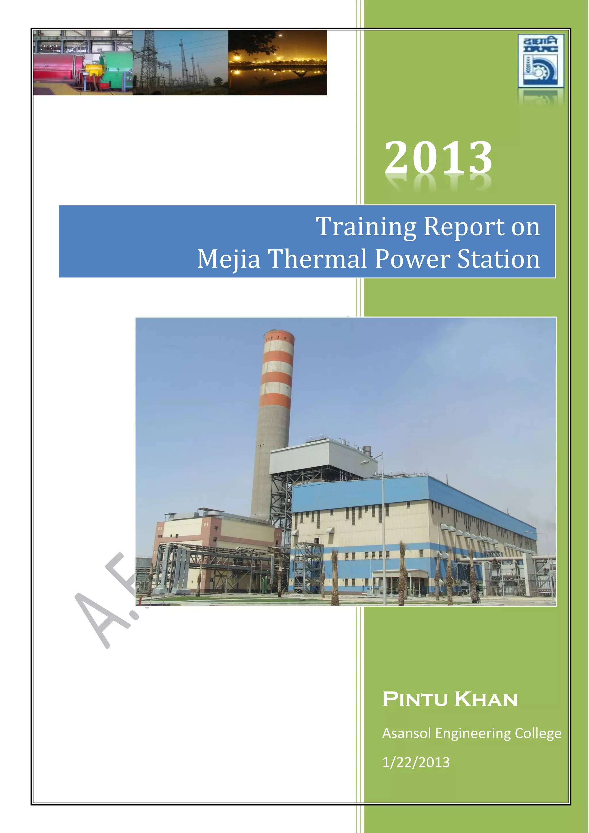
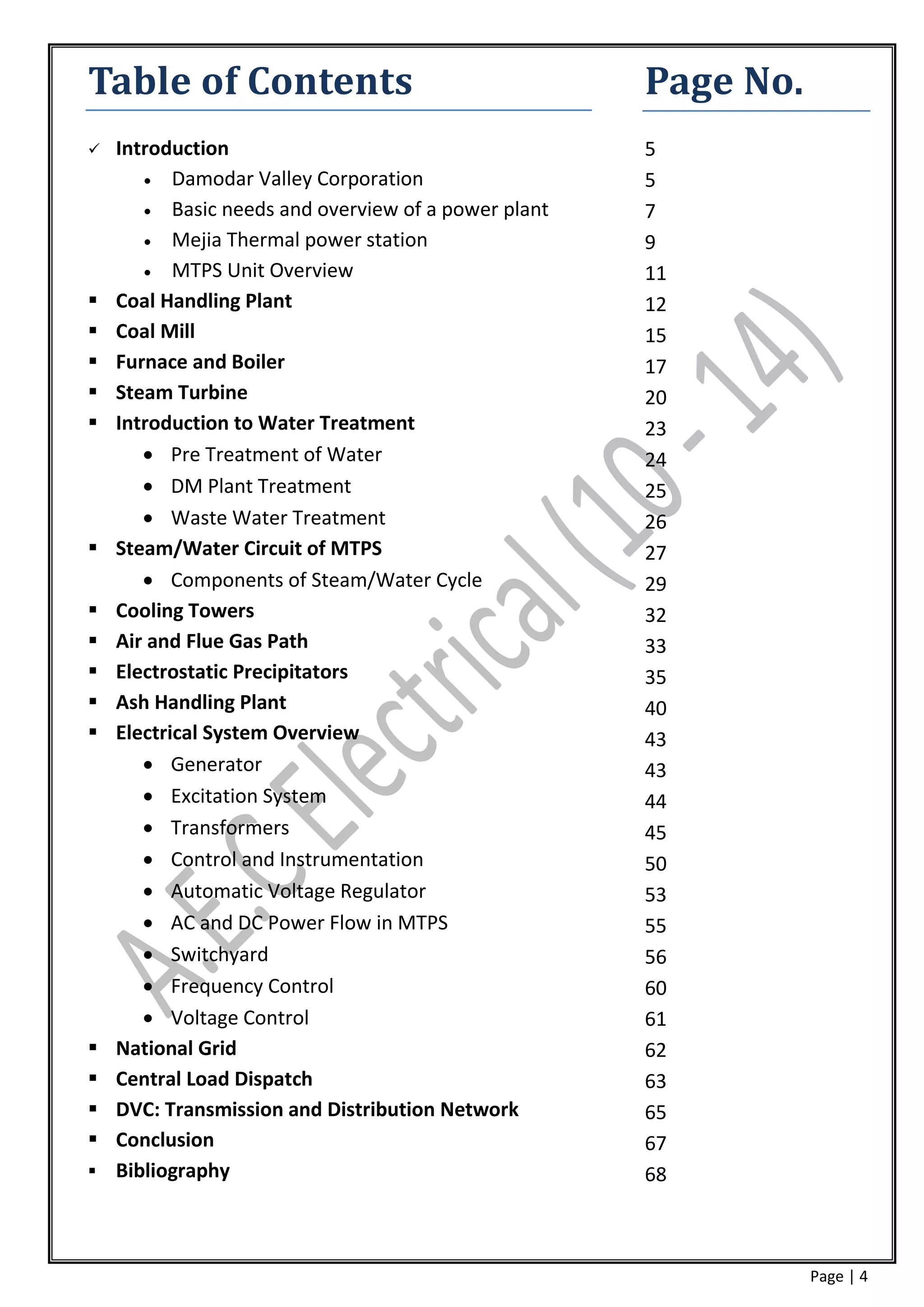
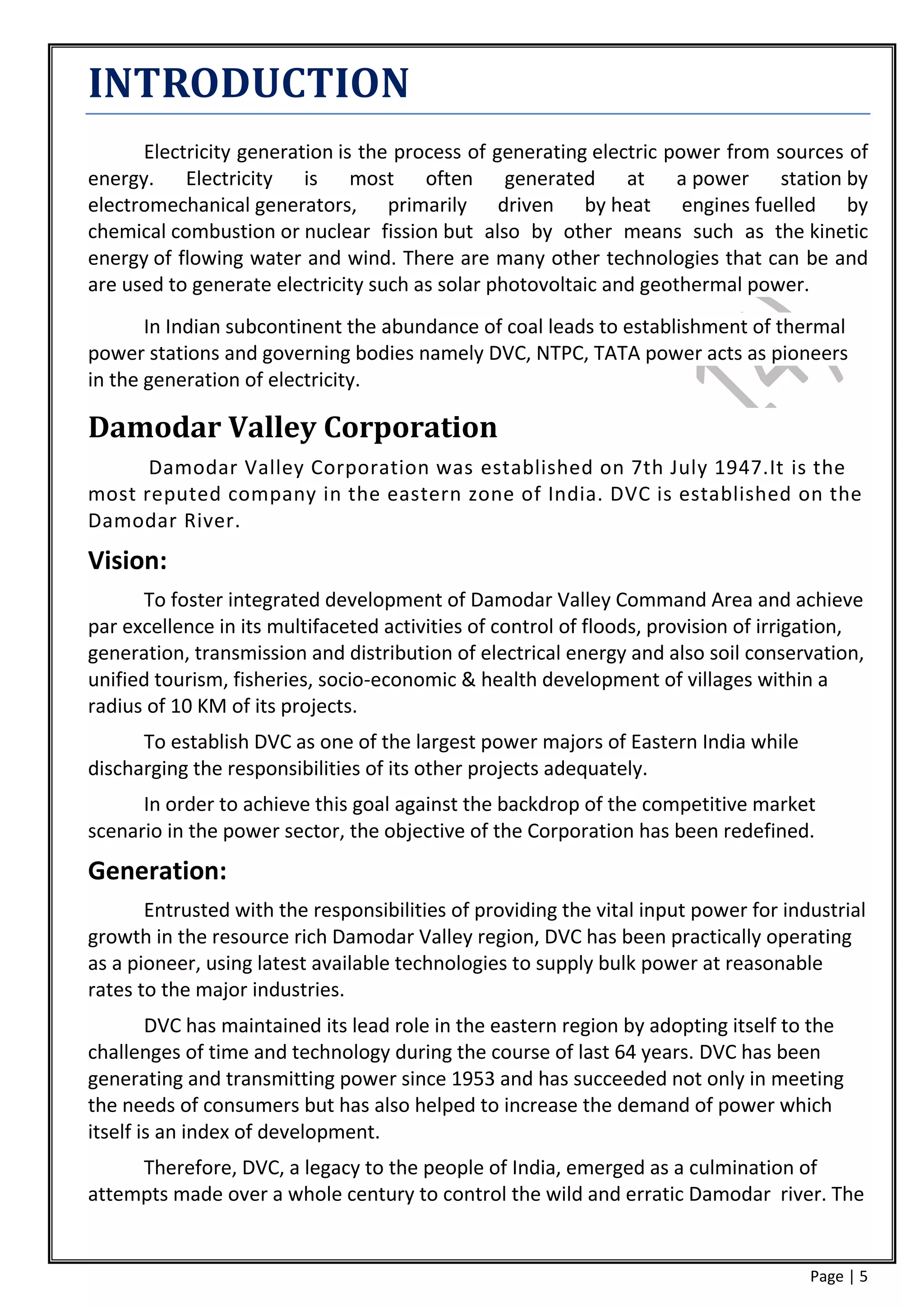
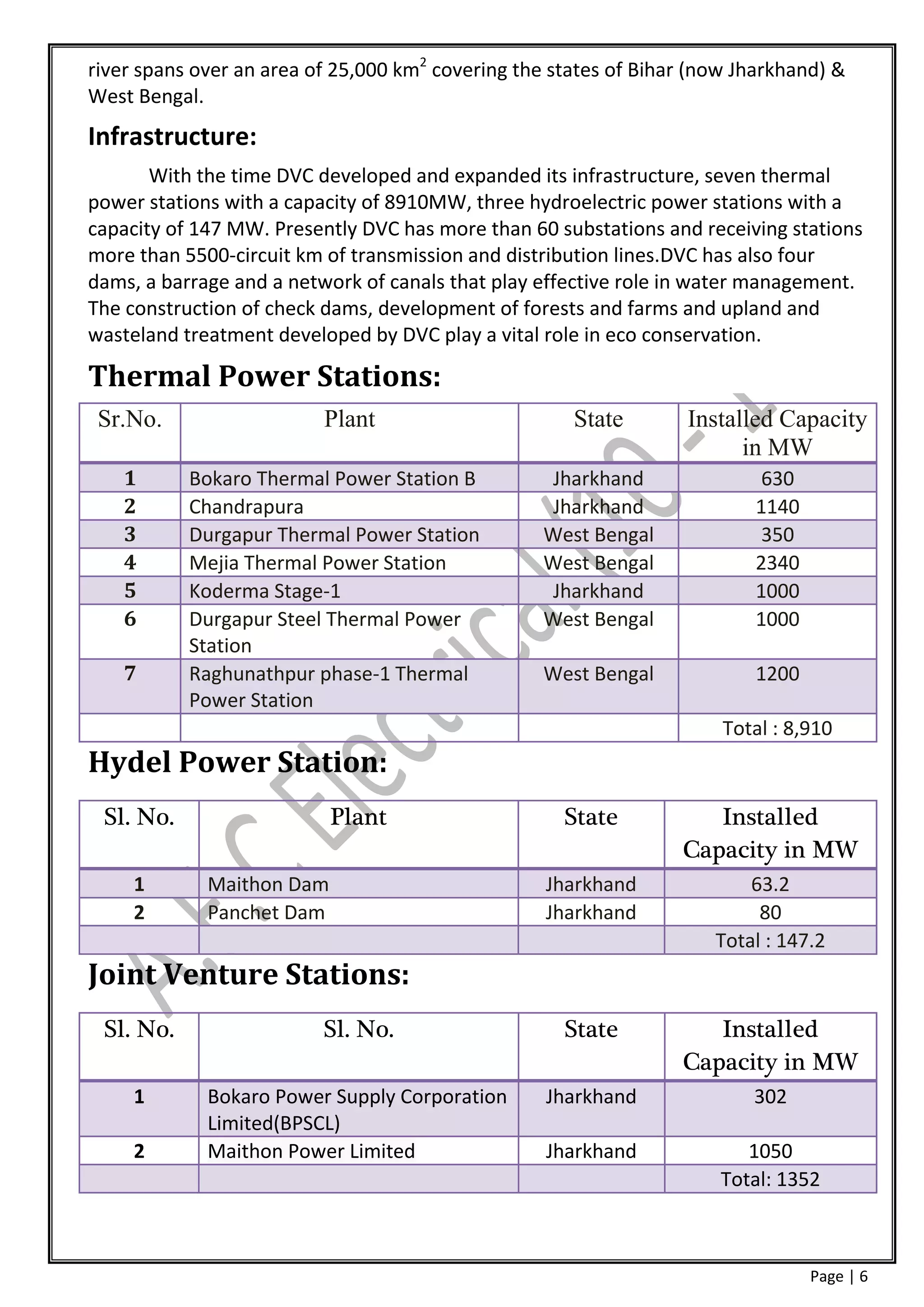
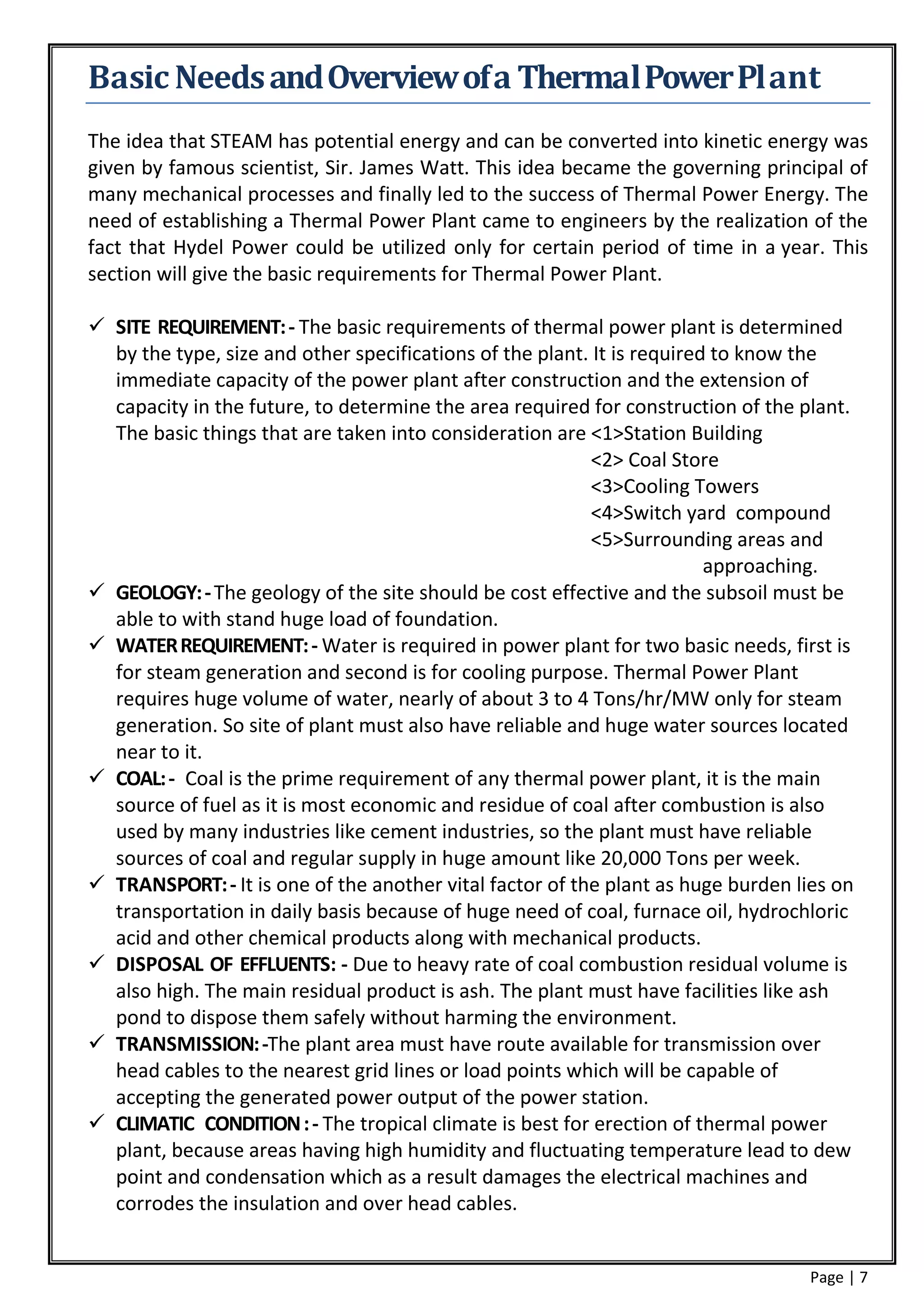
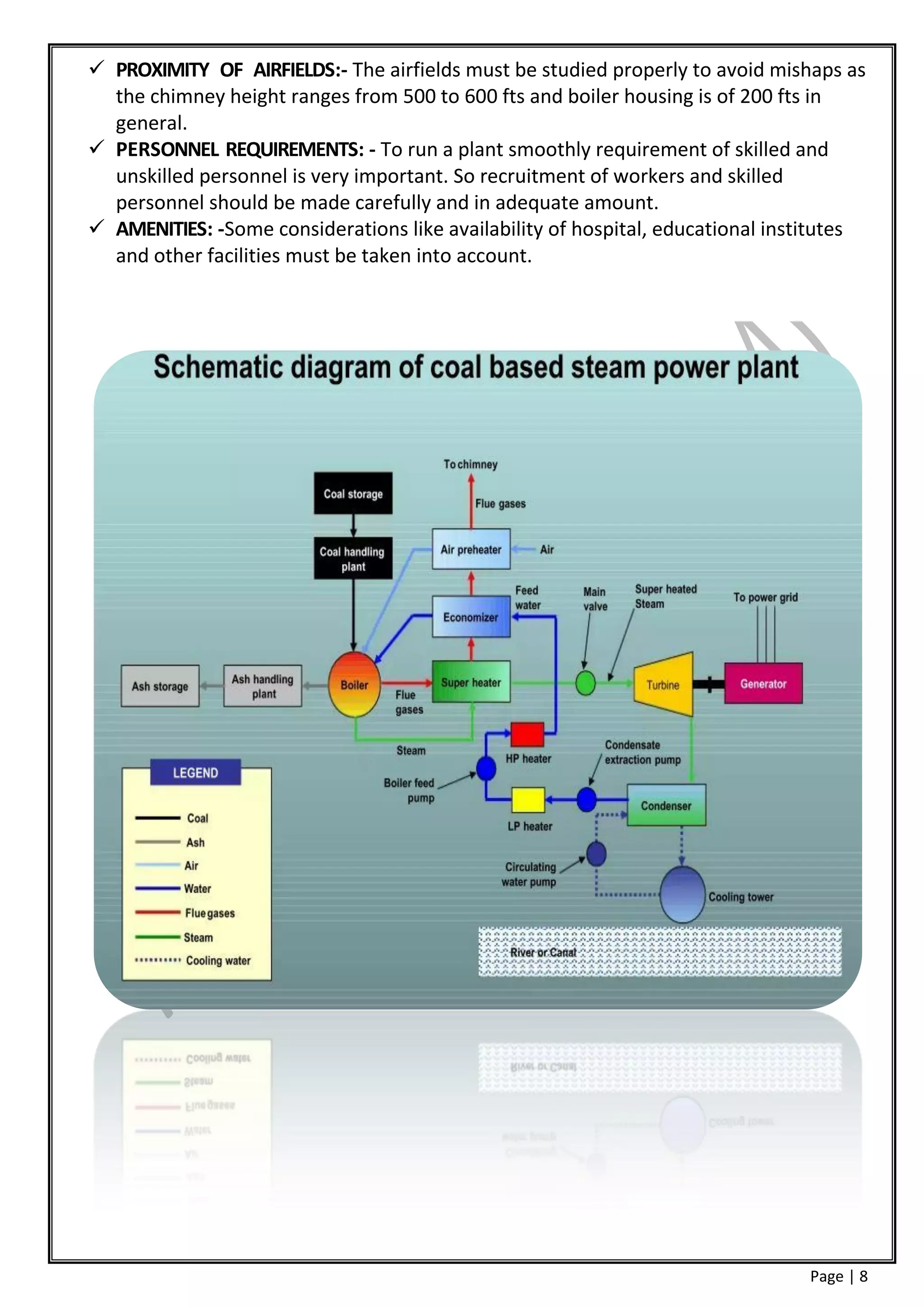
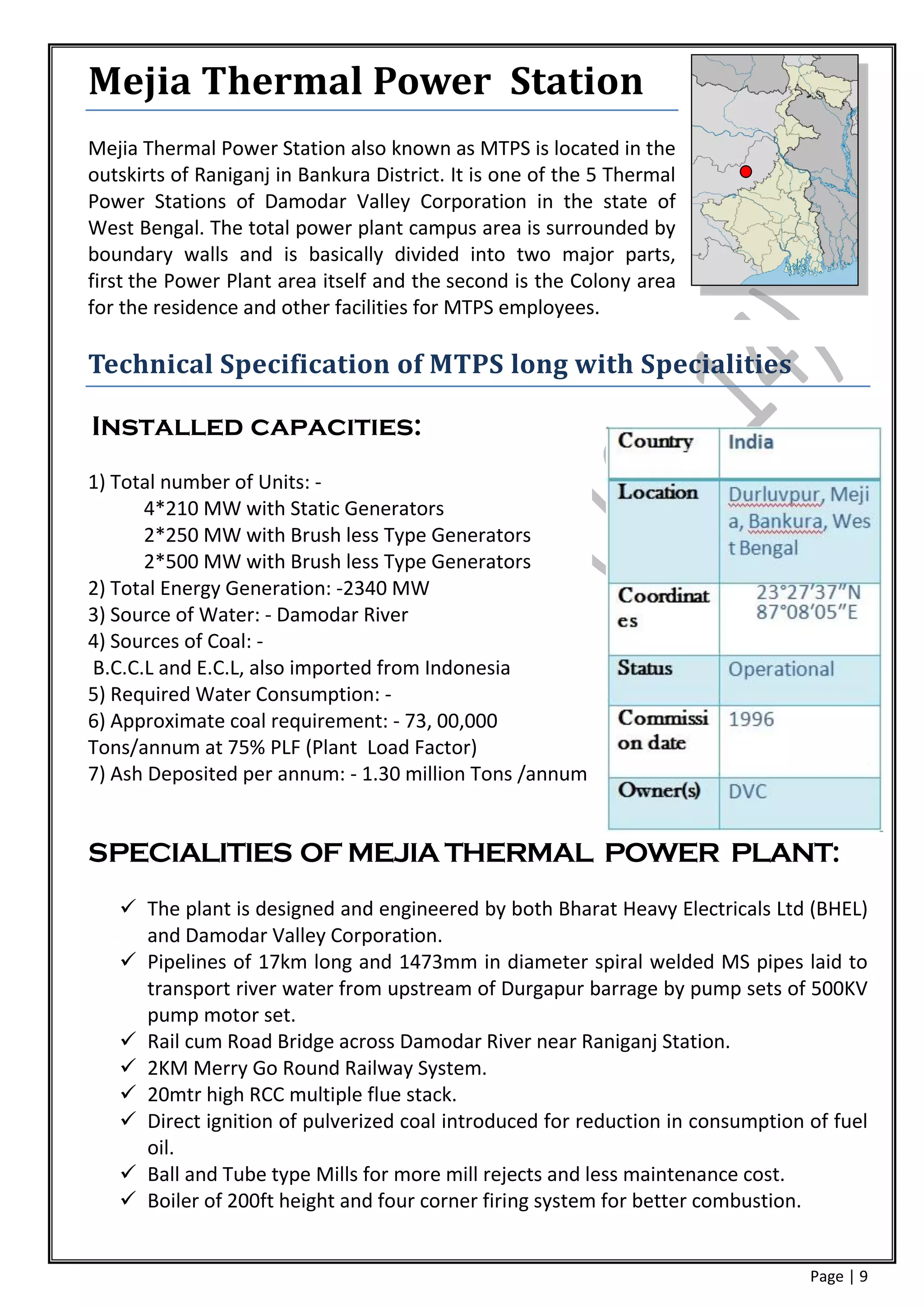
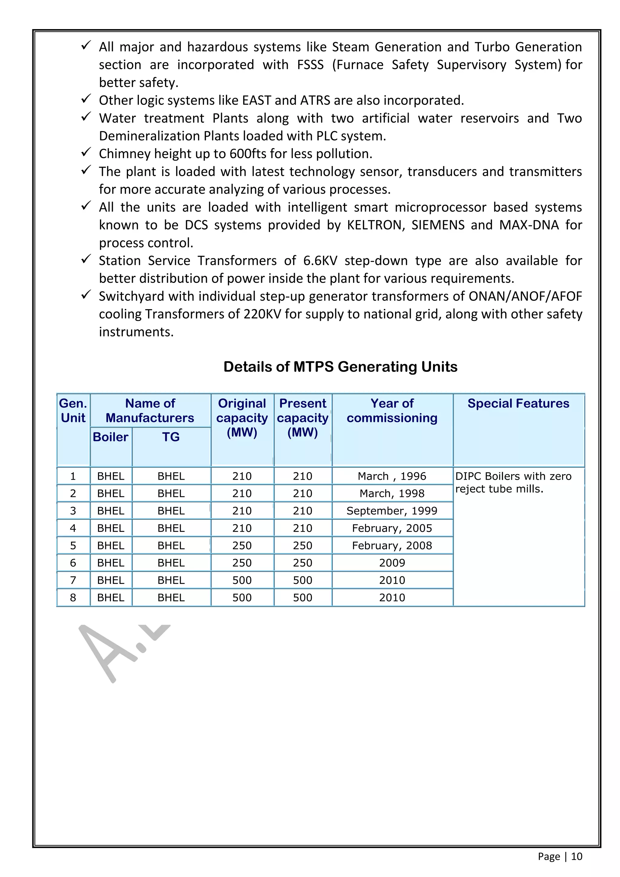
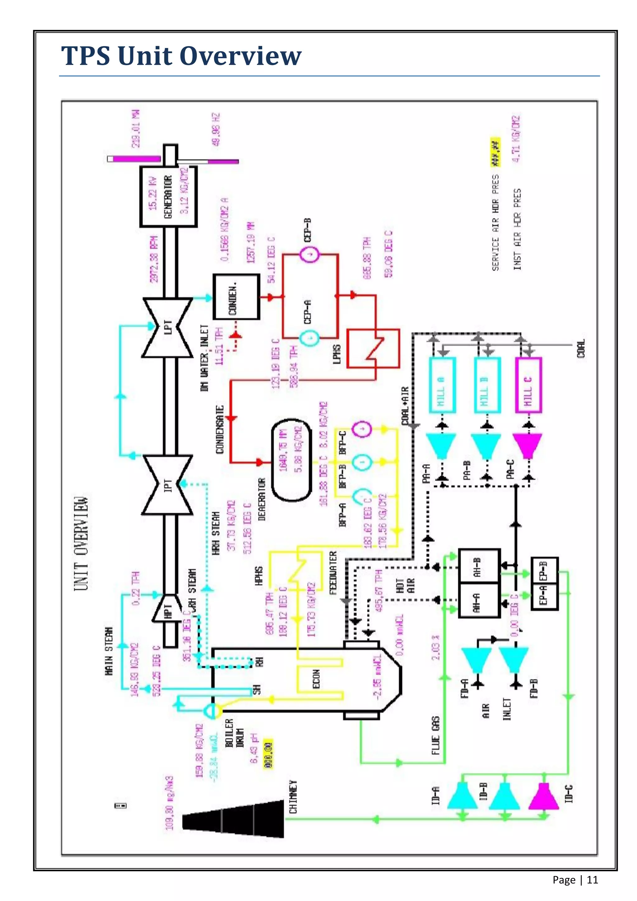
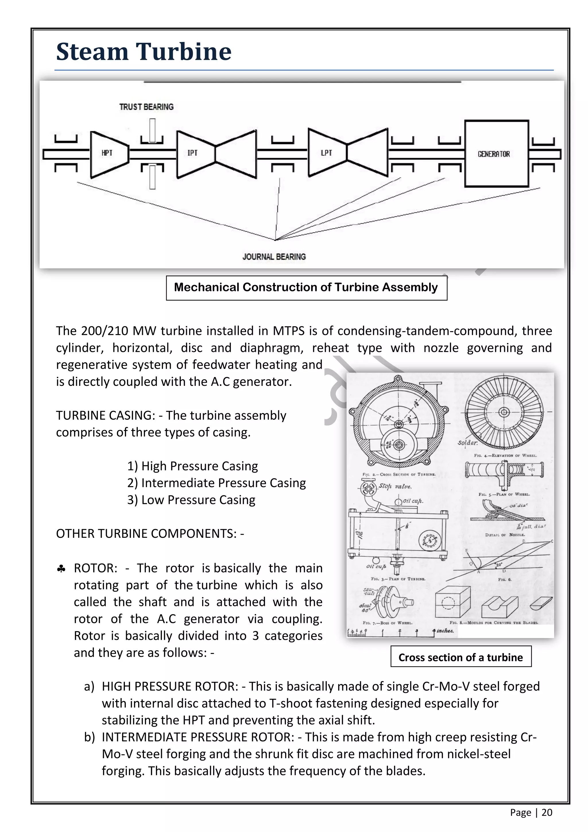
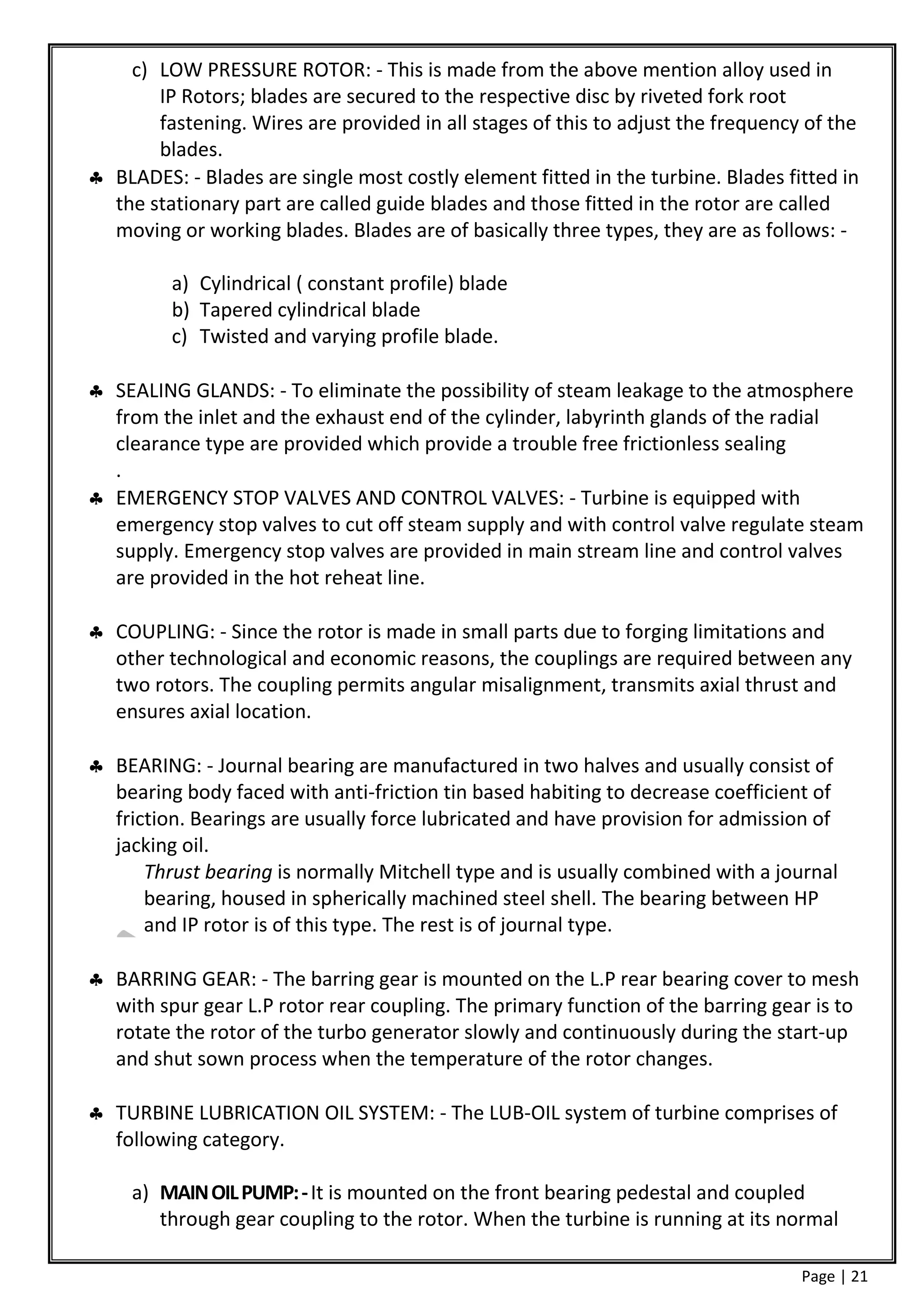

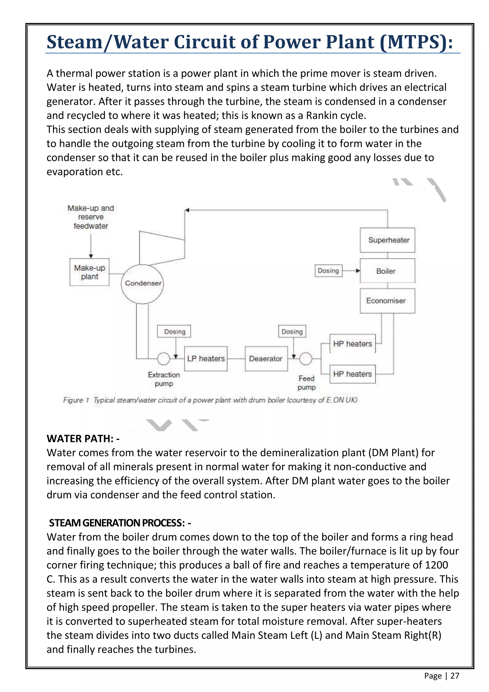
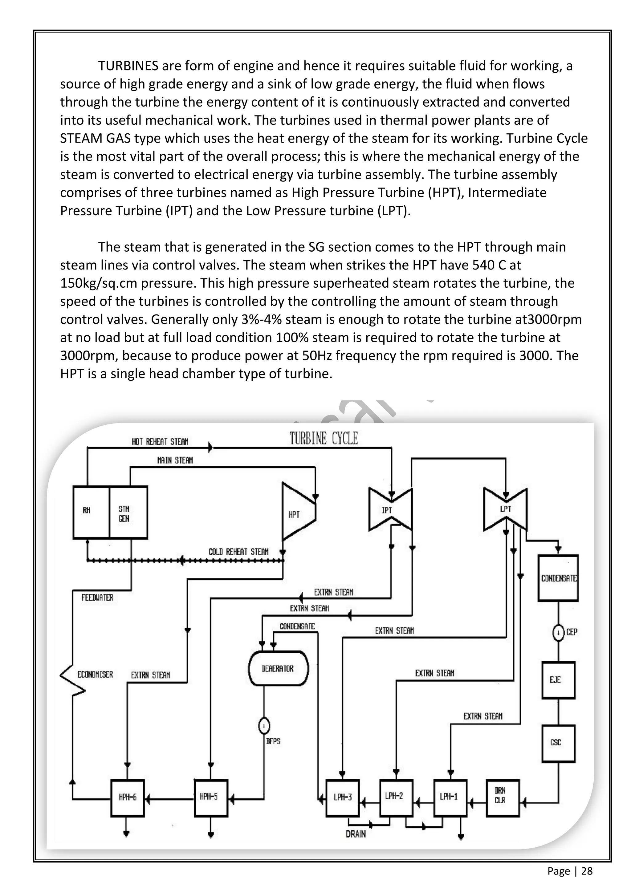
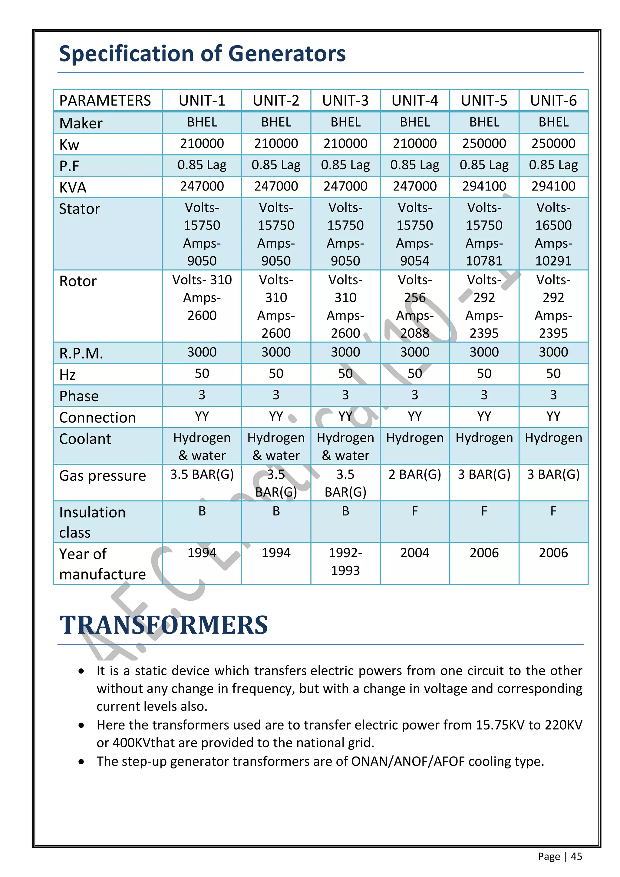
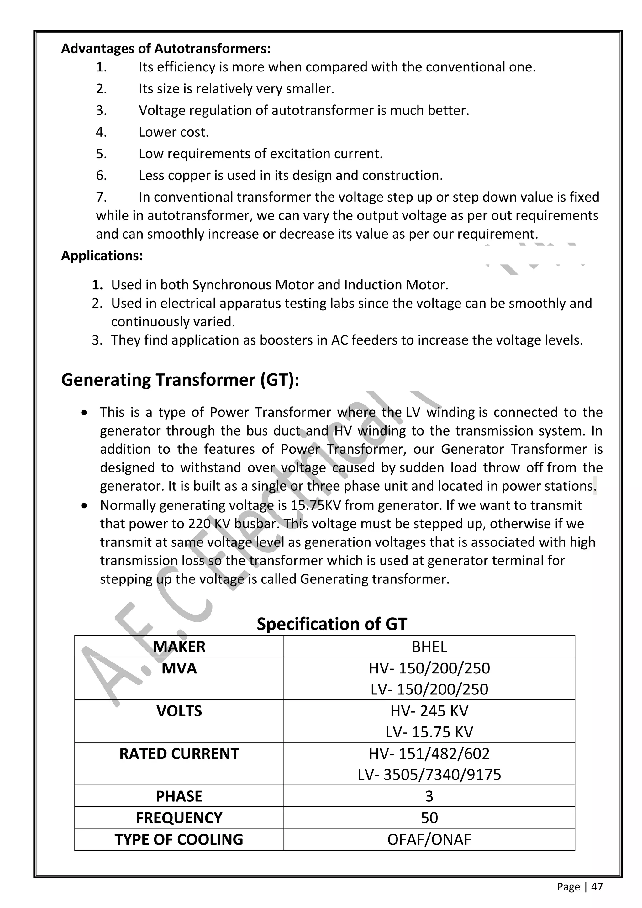
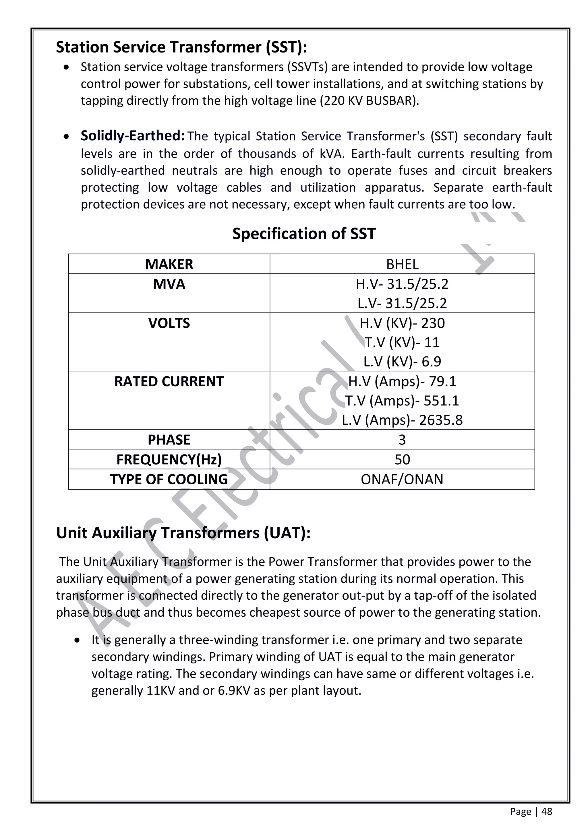

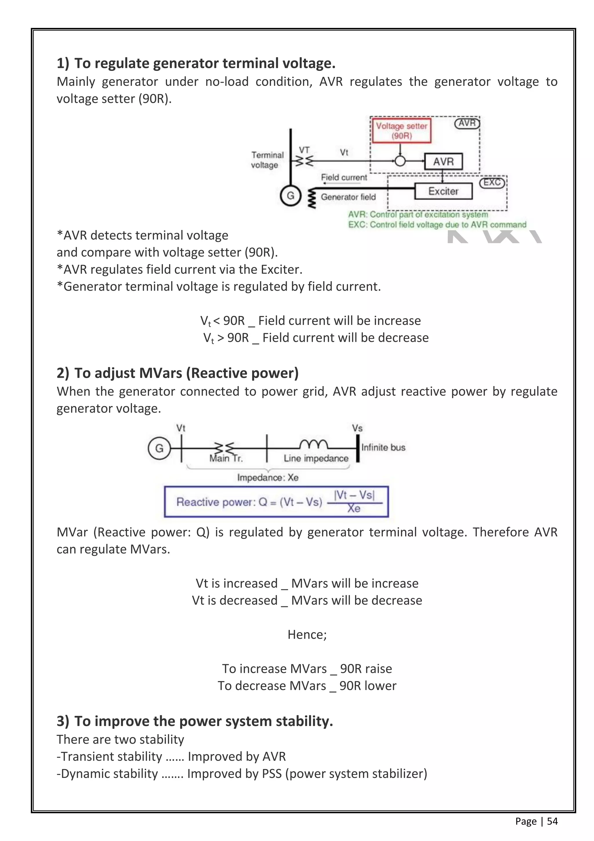
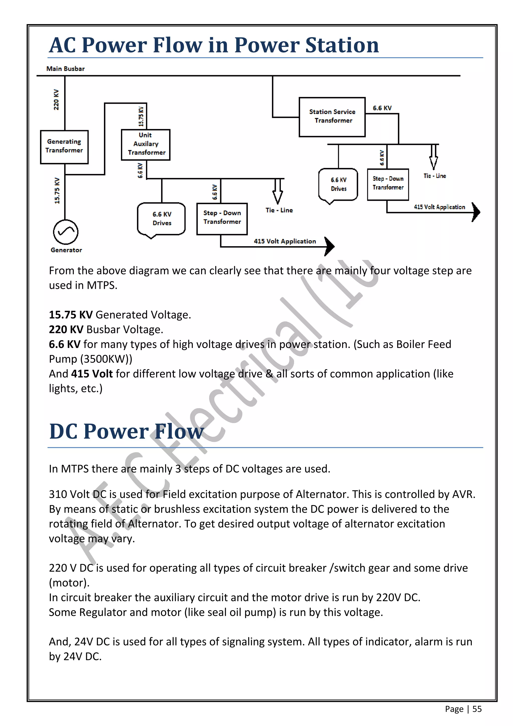
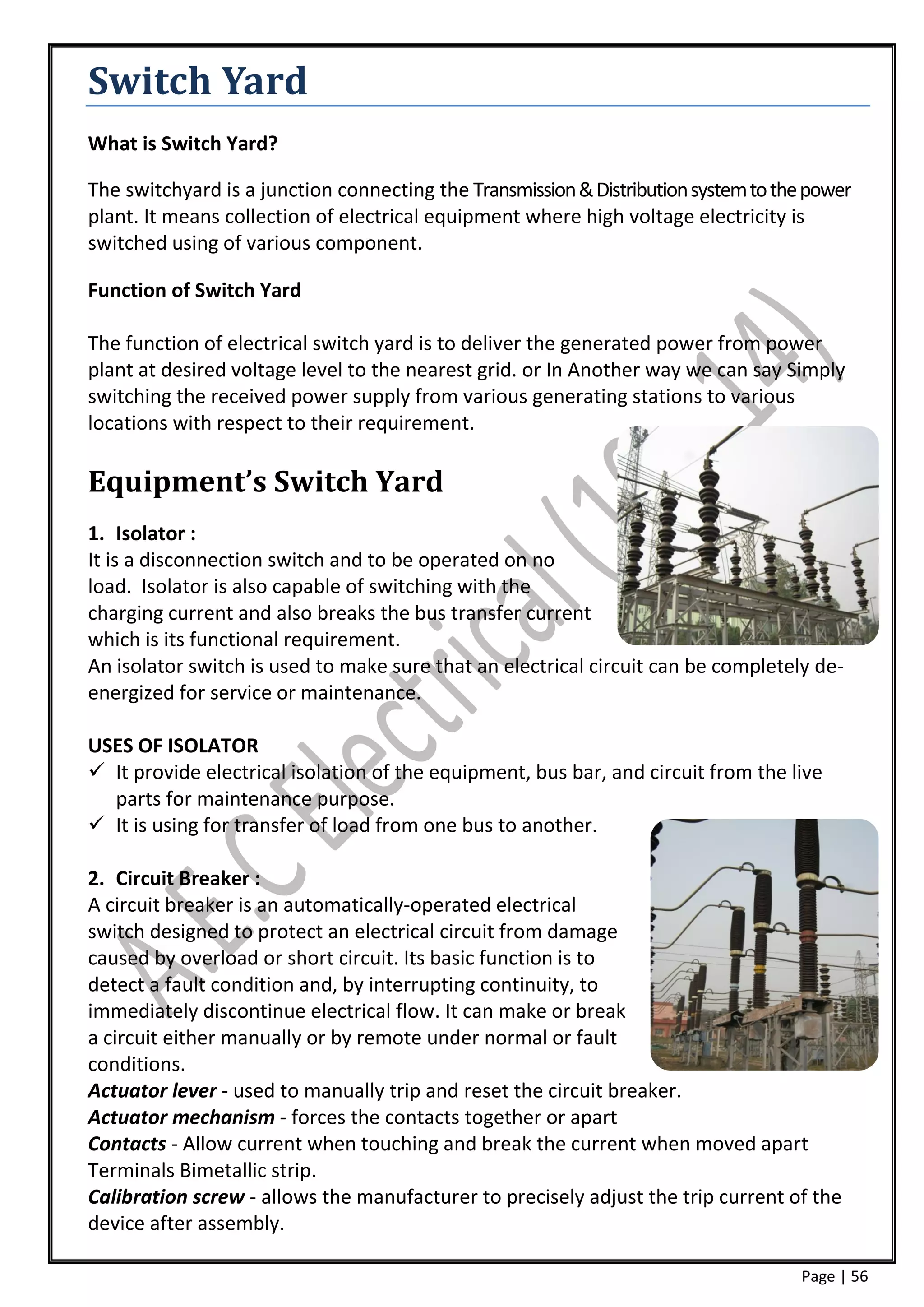
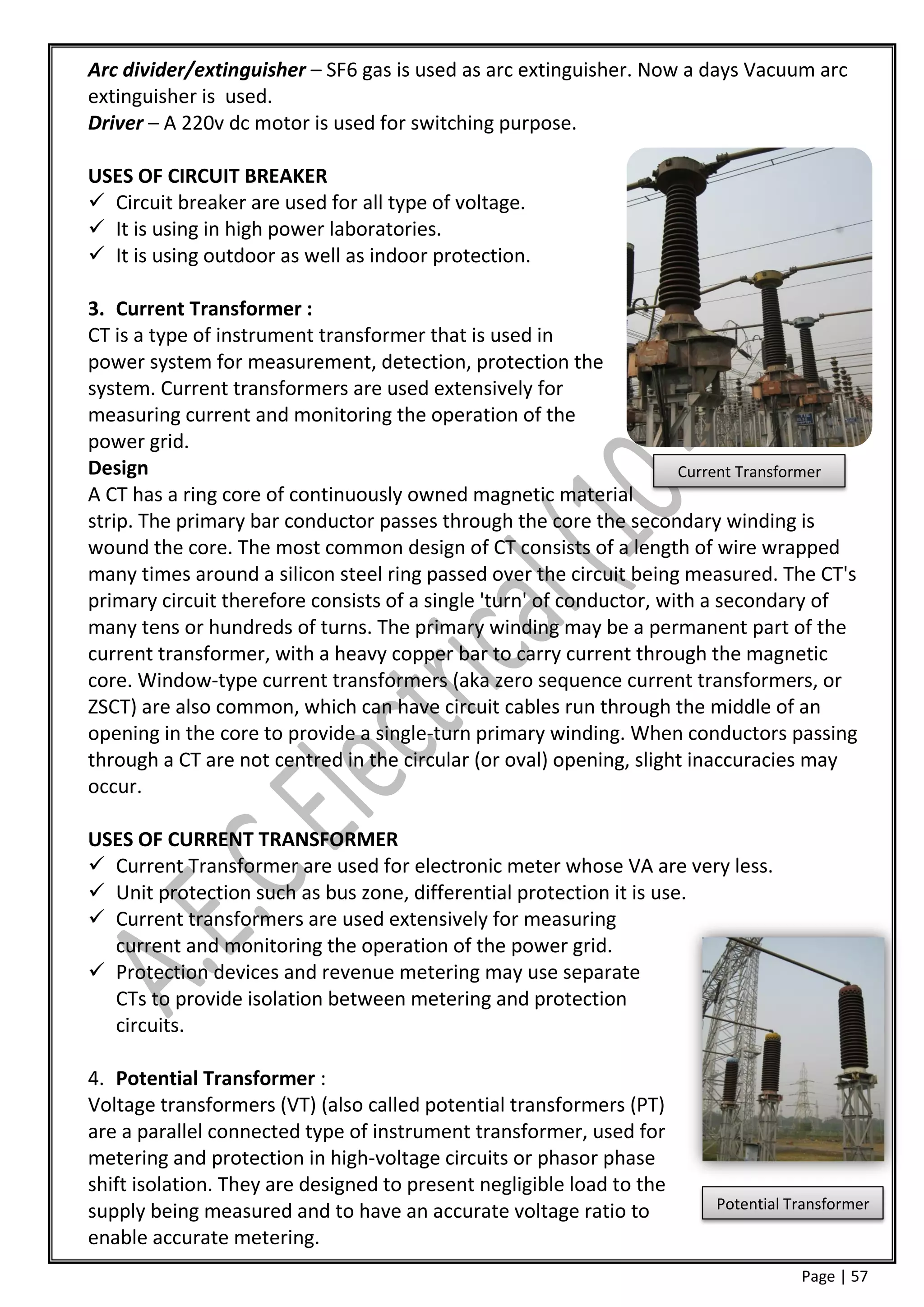
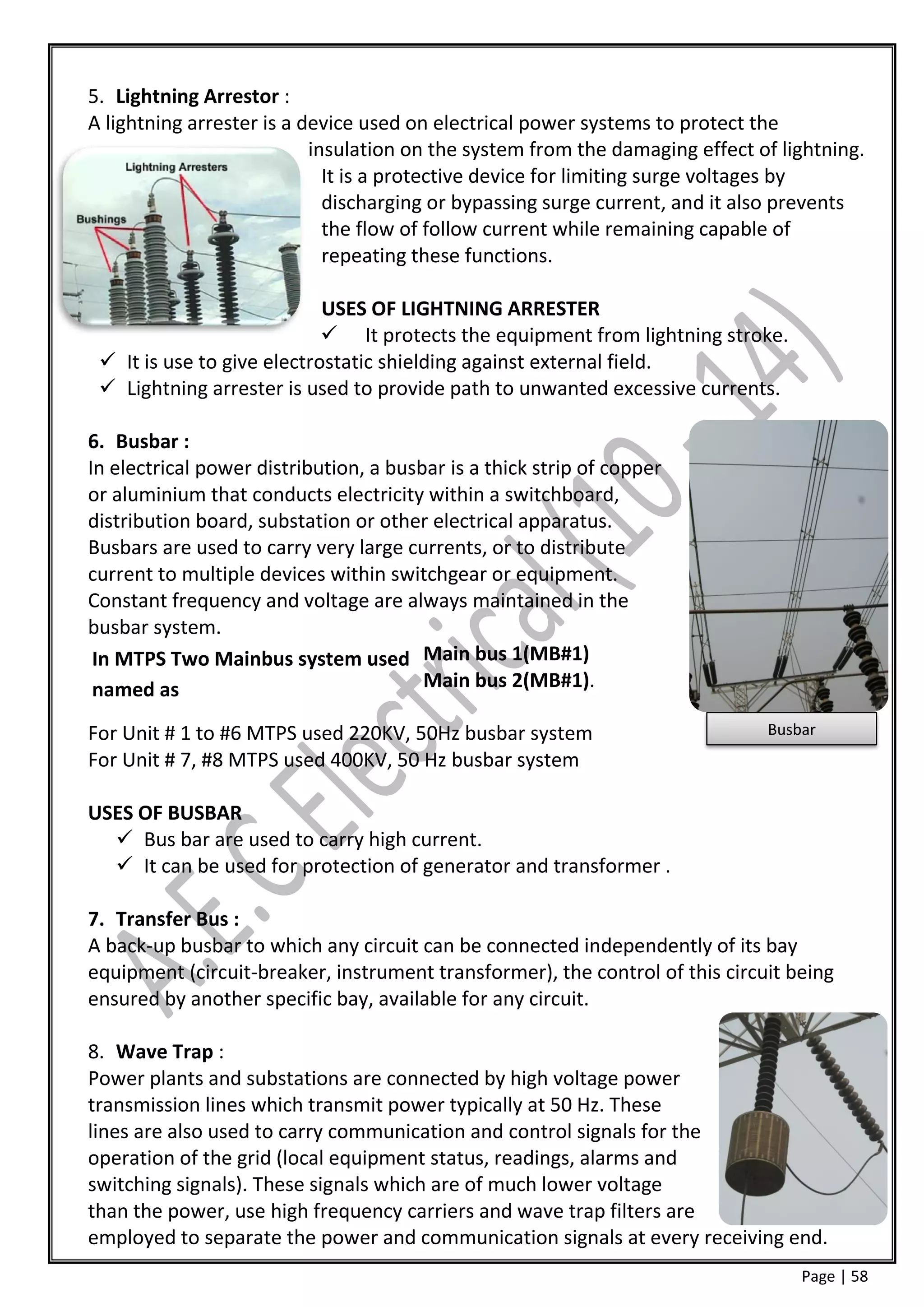
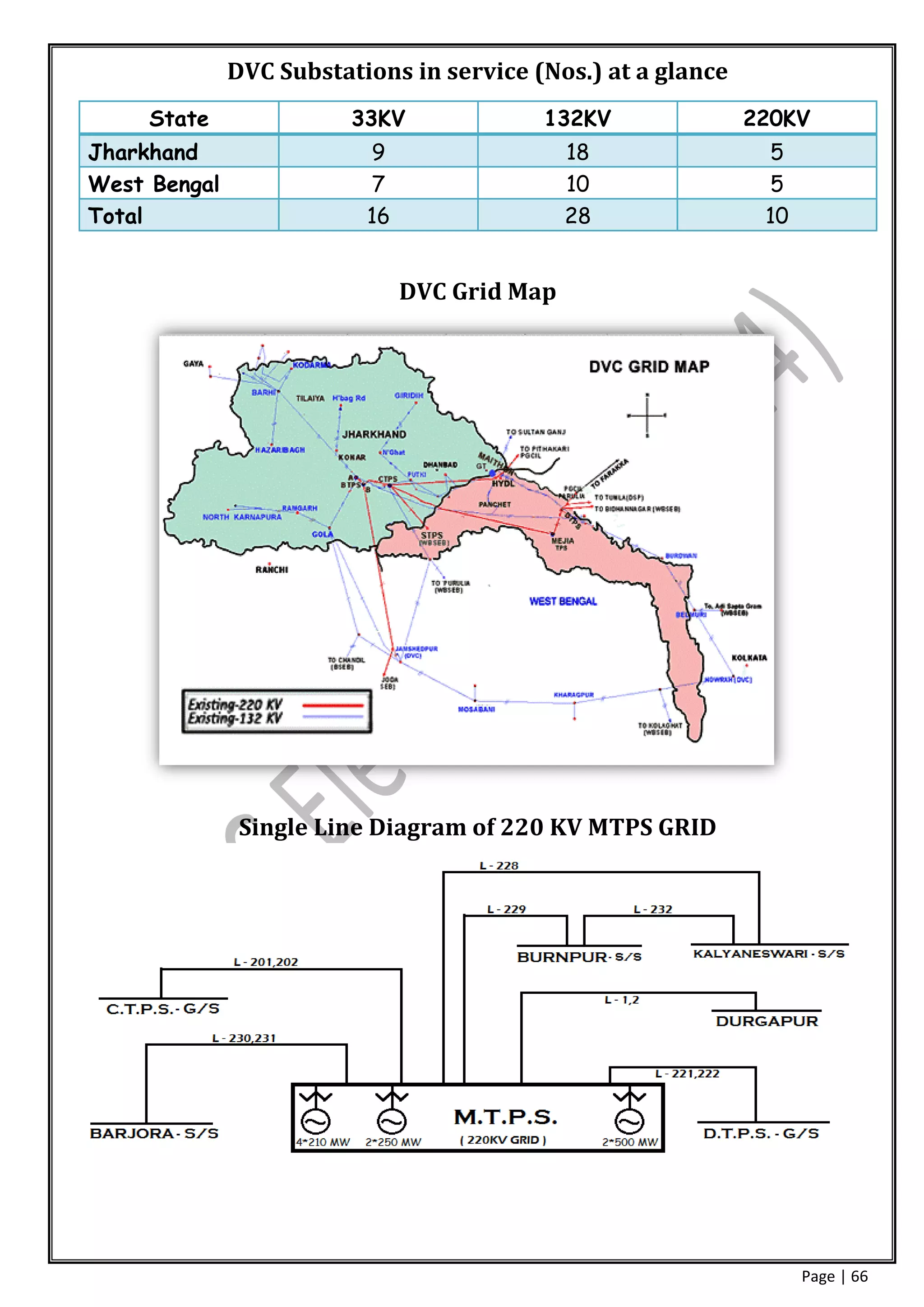

This document provides an overview and training report on Mejia Thermal Power Station operated by Damodar Valley Corporation. It includes details of the various processes involved in power generation such as coal handling, coal milling, steam generation in boilers, steam turbine generation, water treatment, steam/water circuits, cooling towers, flue gas handling, electrostatic precipitators, ash handling, and the electrical systems including generators, transformers, control and instrumentation. The report was prepared by an engineering student as part of an industrial training program to understand the mechanical, electrical, and operational aspects of a thermal power plant.


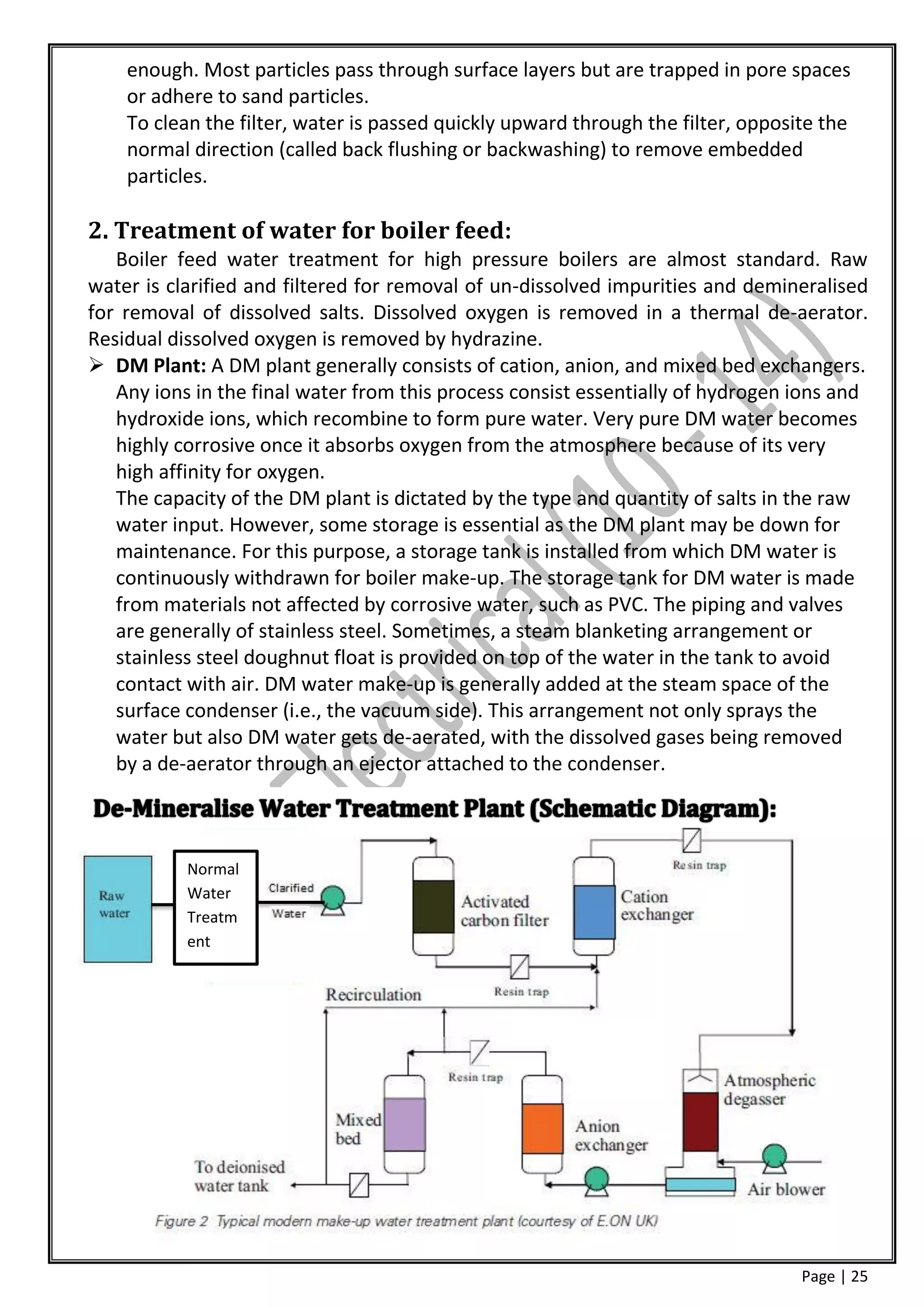
![Vibe Coding vs. Spec-Driven Development [Free Meetup]](https://cdn.slidesharecdn.com/ss_thumbnails/vibecodingvsspecdrivendevelopment-251209105622-43f455e7-thumbnail.jpg?width=640&height=640&fit=bounds)


