Download to read offline
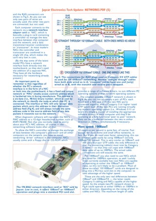
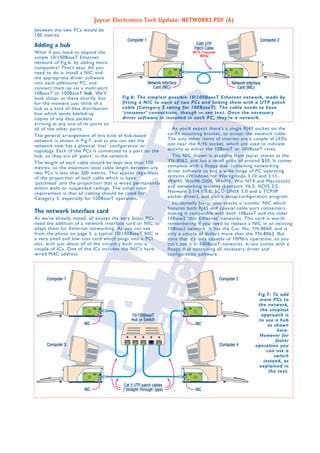
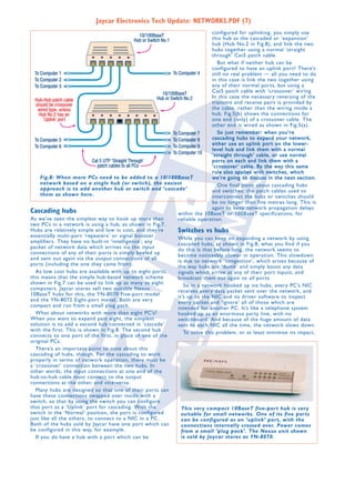
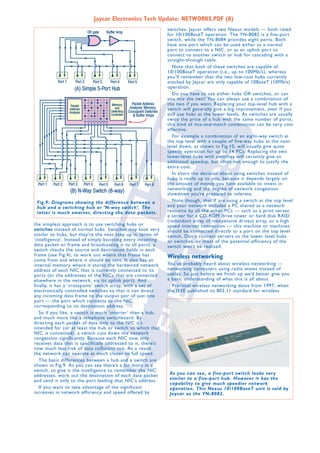

1) Networking computers together allows them to share resources like printers, storage, and internet connections. Recent advances in hardware and software have made networking easier and cheaper than ever. 2) Early computer networking involved connecting remote terminals to mainframe computers. Ethernet was developed in the 1970s and standardized in the 1980s, allowing multiple computers and printers to communicate over coaxial or twisted pair cabling. 3) USB networking using special adapter cables provides an easy way to connect 2-3 computers without installing networking cards, achieving data transfer rates of around 5Mb/s.


![5G Explained! A High Level Overview [Introduction]](https://cdn.slidesharecdn.com/ss_thumbnails/5gexplainedahighleveloverview-260119165306-cc137a3e-thumbnail.jpg?width=640&height=640&fit=bounds)


