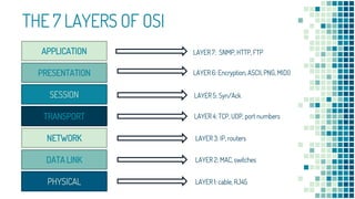
NETWORK
LAYERS
LECTURE AGENDA
 Define OSI and TCP/IP Model
 Discuss and Define the 7 Layers
of OSI and how they work
together.
 Discuss and Define the 4 Layers
of TCP/IP and their function
 Compare OSI and TCP/IP
“
In computer science, the concept of
network layers is a framework that helps to
understand complex network interactions.
There are two models that are widely
referenced today: OSI and TCP/IP. The
concepts are similar, but the layers
themselves differ between the two models.
What is OSI Model?
Open Systems Interconnection
 provides a general framework for standardization
 defines a set of layers and services provided by each layer
 one or more protocols can be developed for each layer
The OSI model was developed by the International
Organization for Standardization.
THE 7 LAYERS OF OSI
APPLICATION
PRESENTATION
SESSION
TRANSPORT
NETWORK
DATA LINK
PHYSICAL
LAYER 7: SNMP, HTTP, FTP
LAYER 6: Encryption, ASCII, PNG, MIDI)
LAYER 5: Syn/Ack
LAYER 4: TCP, UDP, port numbers
LAYER 3: IP, routers
LAYER 2: MAC, switches
LAYER 1: cable, RJ45
LAYER 7: APPLICATION
• Human-Computer Interaction
• Web browsers and other internet-
connected applications (like Skype or
Outlook) use Layer 7 application
protocols.
LAYER 6: PRESENTATION
• Data Representation and Encryption
• This layer converts data to and from
the Application layer. In other words,
it translates application formatting to
network formatting and vice versa.
LAYER 5: SESSION
• Connection Maintenance
• This layer establishes and terminates
connections between devices. It also
determines which packets belong to
which text and image files.
LAYER 4: TRANSPORT
• End-to-End Connections
• This layer coordinates data transfer
between system and hosts, including
error-checking and data recovery.
LAYER 3: NETWORK
• Logical Addressing for data path using packets
• This layer determines how data is sent to the
receiving device. It’s responsible for packet
forwarding, routing, and addressing.
LAYER 2: DATA LINK
• Physical addressing ,formatting data in frames
• Translates binary (or BITs) into signals and
allows upper layers to access media.
LAYER 1: PHYSICAL
• Physical transmission of signals,
media or binary raw bits
• Actual hardware sits at this layer. It
transmits signals over media.
What is TCP/IP?
Transmission Control Protocol/Internet Protocol
TCP
breaks messages into packets,
hands them off to the IP
software for delivery, and then
orders and reassembles the
packets at their destination
IP
deals with the routing of
packets through the maze of
Interconnected networks to
their final destination
THE 4 LAYERS OF TCP/IP
LAYER 4: PROCESS
LAYER 3. HOST TO HOST
LAYER 2
LAYER 1: LINK
APPLICATION
TRANSPORT
NETWORK ACCESS
INTERNET
LAYER 4: APPLICATION
• Also called the Process layer
• This layer combines the OSI model’s
L5, L6, and L7.
LAYER 3: TRANSPORT
• Also called the Host-to-Host layer.
• This layer is similar to the OSI
model’s L4.
LAYER 2: INTERNET
• This layer is similar to the OSI
model’s L3.
LAYER 1: PHYSICAL
• Also called the Link or Network
Interface layer.
• This layer combines the OSI model’s
L1 and L2.
21
APPLICATION
TRANSPORT
NETWORK ACCESS
INTERNET
APPLICATION
PRESENTATION
SESSION
TRANSPORT
NETWORK
DATA LINK
PHYSICAL PHYSICAL
OSI TCP/IP
How Network Layers Work?
Sender Receiver
Let’s understand how this image is send to other network using the 7 Layers
NETWORK B
NETWORK A
Application Layer:
Skype would be using the File Transfer Protocol to send the dog photo to Network B
NETWORK B
NETWORK A
Sender Receiver
Sender Receiver
Presentation Layer
Pixels of photo will be translated to binary and compresses it
Encrypt Decrypt
NETWORK B
NETWORK A
Sender Receiver
Session Layer:
Establishes, maintains and ends communication between devices
When you download these
files, this layer determines
which data packets belong
to which files
(e.g. text/image/audio), as
well as where these packets
go.
NETWORK B
NETWORK A
Sender Receiver
NETWORK B
NETWORK A
Laptop may be able to handle 100 mbps
Phone can only process 10 mbps
Transport Layer
segments data from session layer
Dictate that the server slow down the data transmission, so nothing is lost by the time
your friend receives it.
Sender Receiver
Network Layer:
transmits data segments between networks in the form of packets
NETWORK B
NETWORK A
this layer assigns source and
destination IP addresses to the
data segments.
192.168.254.254 192.168.1.1
Sender Receiver
Data Link Layer:
receives packets from Layer 3
NETWORK B
NETWORK A
performs physical addressing.
It adds sender and receiver
MAC addresses to the data
packet to form a data unit
called a frame.
00:1A:C2:7B:00:47 70:b2:aa:e6:3c:91
enables frames to be
transported via local media (e.g.
copper wire, optical fiber, or
air).
Sender Receiver
Physical Layer:
converts binary into signals and transmits them over media (e.g. fiber optic)
NETWORK B
NETWORK A
When Network B
receives the signals,
they’re decapsulated, or
translated back into
binary and then into
application data so the
message can be
seen/human-readable.
APPLICATION
PRESENTATION
SESSION
TRANSPORT
NETWORK
DATA LINK
PHYSICAL
APPLICATION
PRESENTATION
SESSION
TRANSPORT
NETWORK
DATA LINK
PHYSICAL
Data Transfer
NETWORK A NETWORK B
Network layers help us understand
how data moves
Human-Readable Computer-Readable
Transmitted Signal
ADVANTAGES DISADVANTAGES
 generic model and acts as a
guidance tool to develop any
network model.
 Changes in one layer do not affect
other layers
 Flexible - distinctly separates
services, interfaces, and protocols
 supports both connection-oriented
services and connectionless services
 restricts its practical
implementation.
 launching timing of this model was
inappropriate.
 Very complex that is slow and costly
 duplication of services in various
layers
 did not meet the practical needs
OSI MODEL
ADVANTAGES DISADVANTAGES
 industry–standard model that can be
effectively deployed in practical
networking problems.
 allows cross-platform
communications among
heterogeneous networks
 open protocol suite
 scalable, client-server architecture
 assigns an IP address to each
computer on the network
 not generic in nature
 does not clearly separate the
concepts of services, interfaces, and
protocols
 does not distinguish between the
data link and the physical layers
 originally designed and implemented
for wide area networks, not
optimized for small networks
(LAN,PAN)
TCP/IP MODEL
REFERENCES:
▪ Alienor.(2018). The Network Layers Explained [with examples]. Plixer
from https://www.plixer.com/blog/network-layers-explained/
▪ Janardhan,J.(2018). Advantages and Disadvantages of the OSI Model.
Tutorial Point from https://www.tutorialspoint.com/Advantages-and-
Disadvantages-of-the-OSI-Model
▪ Janardhan,J.(2018). Advantages and Disadvantages of the OSI Model.
Tutorials Point from https://www.tutorialspoint.com/Advantages-and-
Disadvantages-of-the-OSI-Model
▪ Fendadis,J.(2018). Advantages and Disadvantages of the TCP/IP Model.
Tutorials Point from https://www.tutorialspoint.com/Advantages-and-
Disadvantages-of-the-TCP-IP-Model
Alaba,
Aylah Nicolei
Banaga,
Louis Gabriel
Guittap,
Dhastin Keinne
Pailma,
Zeus Angelo
Genove,
Germaine
Pailma,
Zean Philip
Toledo,
Rolyne Angelyn
PRESENTATION BY

Network layers

  • 1.
  • 2.
    LECTURE AGENDA  DefineOSI and TCP/IP Model  Discuss and Define the 7 Layers of OSI and how they work together.  Discuss and Define the 4 Layers of TCP/IP and their function  Compare OSI and TCP/IP
  • 3.
    “ In computer science,the concept of network layers is a framework that helps to understand complex network interactions. There are two models that are widely referenced today: OSI and TCP/IP. The concepts are similar, but the layers themselves differ between the two models.
  • 4.
    What is OSIModel? Open Systems Interconnection
  • 5.
     provides ageneral framework for standardization  defines a set of layers and services provided by each layer  one or more protocols can be developed for each layer The OSI model was developed by the International Organization for Standardization.
  • 6.
    THE 7 LAYERSOF OSI APPLICATION PRESENTATION SESSION TRANSPORT NETWORK DATA LINK PHYSICAL LAYER 7: SNMP, HTTP, FTP LAYER 6: Encryption, ASCII, PNG, MIDI) LAYER 5: Syn/Ack LAYER 4: TCP, UDP, port numbers LAYER 3: IP, routers LAYER 2: MAC, switches LAYER 1: cable, RJ45
  • 7.
    LAYER 7: APPLICATION •Human-Computer Interaction • Web browsers and other internet- connected applications (like Skype or Outlook) use Layer 7 application protocols.
  • 8.
    LAYER 6: PRESENTATION •Data Representation and Encryption • This layer converts data to and from the Application layer. In other words, it translates application formatting to network formatting and vice versa.
  • 9.
    LAYER 5: SESSION •Connection Maintenance • This layer establishes and terminates connections between devices. It also determines which packets belong to which text and image files.
  • 10.
    LAYER 4: TRANSPORT •End-to-End Connections • This layer coordinates data transfer between system and hosts, including error-checking and data recovery.
  • 11.
    LAYER 3: NETWORK •Logical Addressing for data path using packets • This layer determines how data is sent to the receiving device. It’s responsible for packet forwarding, routing, and addressing.
  • 12.
    LAYER 2: DATALINK • Physical addressing ,formatting data in frames • Translates binary (or BITs) into signals and allows upper layers to access media.
  • 13.
    LAYER 1: PHYSICAL •Physical transmission of signals, media or binary raw bits • Actual hardware sits at this layer. It transmits signals over media.
  • 14.
    What is TCP/IP? TransmissionControl Protocol/Internet Protocol
  • 15.
    TCP breaks messages intopackets, hands them off to the IP software for delivery, and then orders and reassembles the packets at their destination IP deals with the routing of packets through the maze of Interconnected networks to their final destination
  • 16.
    THE 4 LAYERSOF TCP/IP LAYER 4: PROCESS LAYER 3. HOST TO HOST LAYER 2 LAYER 1: LINK APPLICATION TRANSPORT NETWORK ACCESS INTERNET
  • 17.
    LAYER 4: APPLICATION •Also called the Process layer • This layer combines the OSI model’s L5, L6, and L7.
  • 18.
    LAYER 3: TRANSPORT •Also called the Host-to-Host layer. • This layer is similar to the OSI model’s L4.
  • 19.
    LAYER 2: INTERNET •This layer is similar to the OSI model’s L3.
  • 20.
    LAYER 1: PHYSICAL •Also called the Link or Network Interface layer. • This layer combines the OSI model’s L1 and L2.
  • 21.
  • 22.
  • 23.
    Sender Receiver Let’s understandhow this image is send to other network using the 7 Layers NETWORK B NETWORK A
  • 24.
    Application Layer: Skype wouldbe using the File Transfer Protocol to send the dog photo to Network B NETWORK B NETWORK A Sender Receiver
  • 25.
    Sender Receiver Presentation Layer Pixelsof photo will be translated to binary and compresses it Encrypt Decrypt NETWORK B NETWORK A
  • 26.
    Sender Receiver Session Layer: Establishes,maintains and ends communication between devices When you download these files, this layer determines which data packets belong to which files (e.g. text/image/audio), as well as where these packets go. NETWORK B NETWORK A
  • 27.
    Sender Receiver NETWORK B NETWORKA Laptop may be able to handle 100 mbps Phone can only process 10 mbps Transport Layer segments data from session layer Dictate that the server slow down the data transmission, so nothing is lost by the time your friend receives it.
  • 28.
    Sender Receiver Network Layer: transmitsdata segments between networks in the form of packets NETWORK B NETWORK A this layer assigns source and destination IP addresses to the data segments. 192.168.254.254 192.168.1.1
  • 29.
    Sender Receiver Data LinkLayer: receives packets from Layer 3 NETWORK B NETWORK A performs physical addressing. It adds sender and receiver MAC addresses to the data packet to form a data unit called a frame. 00:1A:C2:7B:00:47 70:b2:aa:e6:3c:91 enables frames to be transported via local media (e.g. copper wire, optical fiber, or air).
  • 30.
    Sender Receiver Physical Layer: convertsbinary into signals and transmits them over media (e.g. fiber optic) NETWORK B NETWORK A When Network B receives the signals, they’re decapsulated, or translated back into binary and then into application data so the message can be seen/human-readable.
  • 31.
  • 32.
    Network layers helpus understand how data moves Human-Readable Computer-Readable Transmitted Signal
  • 33.
    ADVANTAGES DISADVANTAGES  genericmodel and acts as a guidance tool to develop any network model.  Changes in one layer do not affect other layers  Flexible - distinctly separates services, interfaces, and protocols  supports both connection-oriented services and connectionless services  restricts its practical implementation.  launching timing of this model was inappropriate.  Very complex that is slow and costly  duplication of services in various layers  did not meet the practical needs OSI MODEL
  • 34.
    ADVANTAGES DISADVANTAGES  industry–standardmodel that can be effectively deployed in practical networking problems.  allows cross-platform communications among heterogeneous networks  open protocol suite  scalable, client-server architecture  assigns an IP address to each computer on the network  not generic in nature  does not clearly separate the concepts of services, interfaces, and protocols  does not distinguish between the data link and the physical layers  originally designed and implemented for wide area networks, not optimized for small networks (LAN,PAN) TCP/IP MODEL
  • 35.
    REFERENCES: ▪ Alienor.(2018). TheNetwork Layers Explained [with examples]. Plixer from https://www.plixer.com/blog/network-layers-explained/ ▪ Janardhan,J.(2018). Advantages and Disadvantages of the OSI Model. Tutorial Point from https://www.tutorialspoint.com/Advantages-and- Disadvantages-of-the-OSI-Model ▪ Janardhan,J.(2018). Advantages and Disadvantages of the OSI Model. Tutorials Point from https://www.tutorialspoint.com/Advantages-and- Disadvantages-of-the-OSI-Model ▪ Fendadis,J.(2018). Advantages and Disadvantages of the TCP/IP Model. Tutorials Point from https://www.tutorialspoint.com/Advantages-and- Disadvantages-of-the-TCP-IP-Model
  • 36.
    Alaba, Aylah Nicolei Banaga, Louis Gabriel Guittap, DhastinKeinne Pailma, Zeus Angelo Genove, Germaine Pailma, Zean Philip Toledo, Rolyne Angelyn PRESENTATION BY