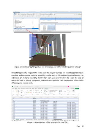
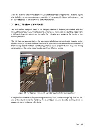
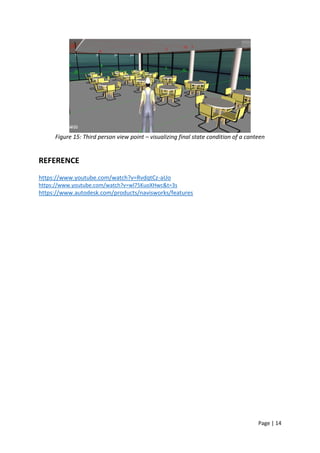
SlideShare a Scribd company logo
1 of 14
Download to read offline
Page | 1
SELF-STUDY 4D BIM ASSIGNMENT
ABDULRASHEED
Page | 2
CONTENTS
DESCRIPTION PAGE
INTRODUCTION 03
1. SECTIONING 04
2. SEARCH SETS 06
3. CLASH DETECTION 07
4. REDLINING 09
5. TIMELINER 10
6. QUANTIFICATION 11
7. THIRD PERSON VIEWPOINT 13
REFLECTION 14
REFERENCE 14
Page | 3
INTRODUCTION
Navisworks Manage is a comprehensive project review tool that can aid project collaboration
of different disciplines, perform clash detection, virtually inspect site based on 3D models,
simulate construction sequence and with a set of review tools to communicate necessary
changes right before construction begins. Navisworks Manage is a software program designed
for project management, coordination, and collaboration in the construction industry.
Navisworks Manage features advanced visualization and simulation capabilities that help
users understand complex designs and identify potential issues in a project's timeline. It also
provides tools for creating, sharing, and collaborating on project data, including reports,
schedules, and material estimates.
Some of the key features of Navisworks Manage include clash detection, time-lining, quantity
take-off, and 4D simulation. Clash detection is one of the unique features of Navisworks
Manage which allows users to identify and resolve clashes between different models, while
time-lining helps users understand the project's timeline and identify potential delays or
issues. Quantity take-off helps users estimate project costs, while 4D simulation allows users
to visualize the construction process in a virtual environment.
Navisworks Manage is widely used in the construction industry, and it is compatible with a
wide range of design and construction software programs, including AutoCAD, Revit, and
SketchUp. It also supports a wide range of file formats, including DWG, DXF, DWF, and IFC. A
variety of files originating from different applications can be brought inside Autodesk
Navisworks and can work with these files for project review purpose. When a change is made
on the original file, this can be reflected within the Navisworks model by clicking on the
REFRESH button.
The following are the native file formats of Navisworks:
NWD Contains all design geometry and the Autodesk Navisworks related data (e.g.
Viewpoints, comments, markups). It has no link to the original file; hence no update
will be shown when changes are made on the original file.
It can be considered as a snapshot of the current state of the model. It is also the file
format of the published model.
NWF A file set that contains the link from the originating file and does not contain model
geometry, thus have a smaller file size.
It is used for an ongoing project where changes are expected in the originating file.
NWC A cache file created when the native file is loaded in Autodesk Navisworks, this
acquires the name of the loaded native file and on the same directory.
If NWC is loaded the next time, the file will check which is newer (original file vs
cache file). If it detects that the original file is newer, the cache will be recreated to
reflect the design update.
In this report, I tried to explore the various features and capabilities of Navisworks Manage
tools and how it can be used by built environment professionals to enhance the efficiency and
Page | 4
effectiveness of building construction projects. And I have tried to examine the use of
Navisworks Manage in a building construction project and its impact on project coordination,
communication, and overall project success.
1. SECTIONING
This tool enables the user to see what is inside the model by having a cut-away view of the
3D model and allow us to view and analyse the internal structure of the model by slicing it
into sections.
Sectioning is very useful as it gives a view through the spaces and surrounding structures that
can reveal the relationships between the different parts of the buildings that might not be
shown in plan drawings. With sectioning tool, we would be able to see and communicate how
a buildings spaces and volumes connect and come together.
For the clients, sectioning views will provide them to see the relationship and enclosures of
the interior spaces. Consultants look at sections to aid in the accurate design of structural,
architectural and M&E components, and Contractor or builders refer to sections during
construction to make sure everything is built as planned.
Figure 1: Sectioned view
There are two sectioning modes available from the Sectioning Tools tab Mode panel: Planes
and Box.
Planes Mode
Planes mode allows us to make up to six sectional cuts in any plane while still being able to
navigate around the scene, enabling us to see inside models without hiding any item.
Page | 5
Plane Name Default Alignment
Plane 1 Top
Plane 2 Bottom
Plane 3 Front
Plane 4 Back
Plane 5 Left
Plane 6 Right
Box Mode
Box mode allows us to focus the review in a specific and limited area of the model. The section
box can be moved, rotated, and scaled with the sectioning gizmos and can also manipulate
the section box numerically.
Figure 2: Box Mode Sectioning
When we create a section plane, we can select any plane in 3D space to slice through the
model. The section plane acts like a virtual blade that cuts through the model which reveals
the internal details of the objects and surfaces that are intersected by the plane. Once we
have created a section plane, we can manipulate it to adjust the angle and position of the
section, as well as change the depth of the slice to reveal more or less of the model. Overall,
the sectioning function is a powerful tool for visualizing and analysing complex 3D models,
helping us to identify potential design conflicts, communicate design ideas more effectively,
and improve project coordination and collaboration.
Page | 6
2. SEARCH SET
The search set function in Navisworks is used to quickly locate and select specific objects or
elements within a large model or scene. It allows users to define specific search criteria and
then applies those criteria to search for objects within the model.
A search set can be created by defining search parameters such as categories, properties,
conditions, names, classifications etc. Once the search set is created, it can be saved and used
repeatedly to quickly locate objects within the model.
Figure 3: Setting of rules for creating Search sets.
Search sets can be very useful when working with complex models that contain many objects.
Instead of manually searching through the model to find specific objects, users can simply
apply the search set to quickly and easily locate the objects they need. And it also can export
the sets we created as specific document such as xml, which can be imported into many other
works and projects. We can use them repeatedly, as well as create Navisworks standards.
Figure 4: Selection of a building element (flexible duct)
Page | 7
For example, user want to search for location and orientation of all flexible duct at roof top.
All the flexible ducts will be selected and highlighted upon creating a search set for based the
setting of rules.
Search set are useful for saving a group of objects on which we want to regularly perform
some action, such as hiding them, changing transparency, clash finding and so on. One of the
powerful functions of search set is that it allows us to save the search criteria so that we could
be able to redo the search later as and when the model changes. This action could save us
time especially when the CAD & Revit files are being subjected to many revisions as it
continued to be updated or amended based on site condition and requirements. And if a new
object is introduced to the model where it meets the criteria of the search then it will be
included in the set automatically without adding it manually.
Figure 5: Flexible duct before and after hiding.
3. CLASH DETECTION
Clash detection is a process of identifying and resolving the potential conflicts or clashes
between various building components and systems in a construction project. Clash Detection
- as the name suggests, it is about playing a โ€œDetectiveโ€ role and finding out clashes among
building element and services, especially M&E services in the building design model. Clash
detection will come into the picture when all the building elements & services (Architectural,
Structural, M&E and others) are integrated into the model. It provides real-time collision
detection during designing which gives the project team some hints to improve the design
among different building systems and ultimately prevent costly remedies after modelling
completion and during construction as well.
There are primarily 3 types of clashes:
Hard Clash
A hard clash occurs when two components of a building intersect or pass through each other.
Soft Clash
Page | 8
Soft Clash occurs when one element is not given the spatial or geometric tolerance and
because of which its buffer zone is breached. It is a type of clash which gets flagged when less
than a set tolerance is detected.
Workflow/4D
Workflow clashes, as the name suggests, are the timeline conflicts. They represent a
mismatch in the scheduling of contractors or when there is a conflict of timeline with
equipment or material delivery. It is knowns as 4D clash as it results from scheduling clashes
that affect the efficiency of the entire construction firm.
Clash detection is carried out by creating a clash tests. A clash test is a set of rules that defines
how the different components of the building models should interact with each other.
Figure 6: Setting up of clash detection test between two selections.
After the clash tests are created, the clash detection process can be run based on the rules
defined in the clash tests and identifies any clashes or conflicts that exist between the
different components by analyzing the model.
Figure 7: Results from a clash detection test. The green and blue highlighted element represents a
clash.
Page | 9
Upon running the clash detection process, the report can be generated in various format such
as viewpoints, text, HTML and XML and can be easily shared with stakeholders for reviewing
and coordination purposes.
Figure 8: Clash detection report generated in HTML format.
By identifying and resolving potential clashes between building components, it will help the
project team to improve the overall quality of the project and reduce the risk of issues arising
during construction or after completion.
4. REDLINING
Redlining refers to the process of making mark-up or annotating a 3D model with notes,
dimensions, symbols, and other graphical elements which will make us to communicate the
information or clashes or design changes or issues or feedback with the stakeholders. This will
improve the communication between different teams and help us to avoid
misunderstandings and thereby prevent costly mistakes.
Page | 10
Figure 9: Redlining - clouding with marked up comments
By providing a clear visualization of potential issues in the model, the redlining is helping us
to identify the errors or inconsistencies and to assisting us to address the issues early in design
process which reduces any reworks that likely to happen. Redlining helps to document the
issues and providing a clear record of the design process and ensuring that all stakeholders
are aware of any modifications made to the model.
The most powerful function of this tool is that it allows us to search for the markups or
comment which have been added in the model. This will be very helpful for complex building
project where itโ€™s more likely to have many comments (minor or major) to be addressed in
order to coordinate and resolve the issues. Builders or contractors can easily check for the
comments by using โ€˜find commentโ€™ option based on comment keywords or date of comment
made or author of the comment or comment tag ID.
5. TIMELINER
Timeliner is a Navisworks tool which helps to plan a construction project and create 4D Bim
construction schedule, where we can manage the timelines and can be used to track progress,
identify potential issues and communicate project status to stakeholders. We can use the
Timeliner function to create visual presentations of the project's progress to share with
stakeholders and helping them to understand the project's timeline and status.
Figure 10: Timeliner-based work breakdown structure and Gantt chart
Page | 11
Timeliner allows to import the planning schedules from a variety of sources such as generic
CSV or Primavera, Microsoft Project and others. And we can then connect and overlay the
tasks in the schedule with objects in the model and allowing us to visualize how the project
will evolve over the time. The planning software that best works for importing in Navisworks
is MS Project. Alternatively, we can manually add the task and planned timeline (Start & End
date) in order to generate the overall construction schedule.
Once we have created a timeline in Navisworks, a corresponding Gantt Chart will be produced
that can be well used to analyze and communicate project progress, identify potential delays
or issues, and make crucial decisions about scheduling and allocating adequate resources. The
timeline function enables to simulate the construction or demolition of the project over time
and allows to play the timeline to view the simulation of the project as it progresses.
Figure 11: Simulation of construction task integrated 3D view
6. QUANTIFICATION
Quantification is a tool that allow us to extract the quantity information from our project
models, thereby helping us to analyze and estimate the cost of a project, track work progress,
and manage resources more effectively.
Quantification is very helpful for project managers to accurately estimate the cost and
materials required for the project, helping to identify potential expense and cost savings, and
can effectively manage the overall budget of the project. So, the quantification is particularly
useful for construction projects, where accurate cost estimates and material quantities are
critical for effective project planning and budgeting.
Page | 12
Figure 12: Particular Lighting fixture can be selected and added into the quantity take off
One of the powerful helps of this tool is that the project team do not need to spend time on
counting and measuring material quantities one by one, as this tools automatically make the
estimates on material quantity. Contractors can use quantification to track the use of
resources such as labour, equipment, materials and optimize their deployment to maximize
efficiency and reduce costs.
Figure 13: Quantity take off list generated in excel file.
Page | 13
After the material take off has been done, quantification tool will generate a material report
that includes the measurements and quantities of the selected objects, and this report can
be export to Excel or other software for further analysis.
7. THIRD PERSON VIEWPOINT
The third person viewpoint refers to the perspective from an external position that does not
involve the user's own view. It allows us to navigate and manipulate the building model from
a different viewpoint, which can be useful for reviewing and analyzing the details of the
building elements.
The third person viewpoint gives the user, especially builders or contractor to get a better
understanding of the available space and spatial relationships between different elements of
the building. It can help them identify any potential issues or conflicts that may arise during
construction as the entire model can be seen from different angles.
Figure 14: Third person view point โ€“ corridor leading to the staircase lobby
It helps to visualize the actual positioning of building utility fixtures like lighting, switches etc.
and architectural items like handrail, doors, windows etc. and thereby assisting them to
review the items easily and effectively.
Page | 14
Figure 15: Third person view point โ€“ visualizing final state condition of a canteen
REFERENCE
https://www.youtube.com/watch?v=RvdqtCz-aUo
https://www.youtube.com/watch?v=wl75KuoXHwc&t=3s
https://www.autodesk.com/products/navisworks/features

More Related Content

What's hot

BIM Construction Scheduling 4D Simulation in Navisworks
BIM Construction Scheduling 4D Simulation in NavisworksBIM Construction Scheduling 4D Simulation in Navisworks
BIM Construction Scheduling 4D Simulation in Navisworks
Le Zhang
ย 
Integrated project-delivery
Integrated project-deliveryIntegrated project-delivery
Integrated project-delivery
Ibrahim Al-Hudhaif
ย 
Dissertation BIM
Dissertation BIMDissertation BIM
Dissertation BIM
Tahir Caratella
ย 

What's hot (20)

์†Œํ”„ํŠธ์›จ์–ด ์•„ํ‚คํ…์ฒ˜ ํ‰๊ฐ€(Atam)
์†Œํ”„ํŠธ์›จ์–ด ์•„ํ‚คํ…์ฒ˜ ํ‰๊ฐ€(Atam)์†Œํ”„ํŠธ์›จ์–ด ์•„ํ‚คํ…์ฒ˜ ํ‰๊ฐ€(Atam)
์†Œํ”„ํŠธ์›จ์–ด ์•„ํ‚คํ…์ฒ˜ ํ‰๊ฐ€(Atam)
ย 
Navisworks Clash Course
Navisworks Clash CourseNavisworks Clash Course
Navisworks Clash Course
ย 
Dynamo for Revit โ€“ Bill Knittle, Synergis
Dynamo for Revit โ€“ Bill Knittle, SynergisDynamo for Revit โ€“ Bill Knittle, Synergis
Dynamo for Revit โ€“ Bill Knittle, Synergis
ย 
Key Scopes in DITA 1.3
Key Scopes in DITA 1.3Key Scopes in DITA 1.3
Key Scopes in DITA 1.3
ย 
Hess City Elements 2014 Pole Lighting system
Hess City Elements 2014 Pole Lighting systemHess City Elements 2014 Pole Lighting system
Hess City Elements 2014 Pole Lighting system
ย 
Revit Structure Training
Revit Structure TrainingRevit Structure Training
Revit Structure Training
ย 
A Case Study of Using Combined BIM and GIS Model for Building Energy Conserva...
A Case Study of Using Combined BIM and GIS Model for Building Energy Conserva...A Case Study of Using Combined BIM and GIS Model for Building Energy Conserva...
A Case Study of Using Combined BIM and GIS Model for Building Energy Conserva...
ย 
BIM Construction Scheduling 4D Simulation in Navisworks
BIM Construction Scheduling 4D Simulation in NavisworksBIM Construction Scheduling 4D Simulation in Navisworks
BIM Construction Scheduling 4D Simulation in Navisworks
ย 
Cost Comparisons 3dbuildingprint vs traditional house methods
Cost Comparisons 3dbuildingprint vs traditional house methods Cost Comparisons 3dbuildingprint vs traditional house methods
Cost Comparisons 3dbuildingprint vs traditional house methods
ย 
Integrated project-delivery
Integrated project-deliveryIntegrated project-delivery
Integrated project-delivery
ย 
Ch16 component based software engineering
Ch16 component based software engineeringCh16 component based software engineering
Ch16 component based software engineering
ย 
Bim codes (new egyptian code)
Bim codes (new egyptian code)Bim codes (new egyptian code)
Bim codes (new egyptian code)
ย 
Project management for engineers and architects
Project management for engineers and architectsProject management for engineers and architects
Project management for engineers and architects
ย 
BIM
BIMBIM
BIM
ย 
Create a PHP Library the right way
Create a PHP Library the right wayCreate a PHP Library the right way
Create a PHP Library the right way
ย 
๋””์ง€ํ„ธํŠธ์œˆ ๋ช‡๋ช‡ ๊ธฐ์ˆ  ๋™ํ–ฅ๊ณผ ์‚ฌ๋ก€ - ๋Œ€ํ•œ๊ณต๊ฐ„์ •๋ณดํ•™ํšŒ ์‹ ๋…„ํ•™์ˆ ๋Œ€ํšŒ ๋ฐœํ‘œ ์ž๋ฃŒ
๋””์ง€ํ„ธํŠธ์œˆ ๋ช‡๋ช‡ ๊ธฐ์ˆ  ๋™ํ–ฅ๊ณผ ์‚ฌ๋ก€ - ๋Œ€ํ•œ๊ณต๊ฐ„์ •๋ณดํ•™ํšŒ ์‹ ๋…„ํ•™์ˆ ๋Œ€ํšŒ ๋ฐœํ‘œ ์ž๋ฃŒ๋””์ง€ํ„ธํŠธ์œˆ ๋ช‡๋ช‡ ๊ธฐ์ˆ  ๋™ํ–ฅ๊ณผ ์‚ฌ๋ก€ - ๋Œ€ํ•œ๊ณต๊ฐ„์ •๋ณดํ•™ํšŒ ์‹ ๋…„ํ•™์ˆ ๋Œ€ํšŒ ๋ฐœํ‘œ ์ž๋ฃŒ
๋””์ง€ํ„ธํŠธ์œˆ ๋ช‡๋ช‡ ๊ธฐ์ˆ  ๋™ํ–ฅ๊ณผ ์‚ฌ๋ก€ - ๋Œ€ํ•œ๊ณต๊ฐ„์ •๋ณดํ•™ํšŒ ์‹ ๋…„ํ•™์ˆ ๋Œ€ํšŒ ๋ฐœํ‘œ ์ž๋ฃŒ
ย 
mago3D ํ•œ๊ตญ์–ด ์†Œ๊ฐœ ์ž๋ฃŒ
mago3D ํ•œ๊ตญ์–ด ์†Œ๊ฐœ ์ž๋ฃŒ mago3D ํ•œ๊ตญ์–ด ์†Œ๊ฐœ ์ž๋ฃŒ
mago3D ํ•œ๊ตญ์–ด ์†Œ๊ฐœ ์ž๋ฃŒ
ย 
Jenkins Shared Libraries
Jenkins Shared LibrariesJenkins Shared Libraries
Jenkins Shared Libraries
ย 
Dissertation BIM
Dissertation BIMDissertation BIM
Dissertation BIM
ย 
Portfolio di Laurea
Portfolio di LaureaPortfolio di Laurea
Portfolio di Laurea
ย 

Similar to Naviswork - Self study work.pdf

SDA - 6 -Chapter Six.pdf
SDA - 6 -Chapter Six.pdfSDA - 6 -Chapter Six.pdf
SDA - 6 -Chapter Six.pdf
Kokebe2
ย 
Elevate Your AutoCAD Assignments: Unleash Your Designing Potential!
Elevate Your AutoCAD Assignments: Unleash Your Designing Potential!Elevate Your AutoCAD Assignments: Unleash Your Designing Potential!
Elevate Your AutoCAD Assignments: Unleash Your Designing Potential!
AutoCAD Assignment Help
ย 
Frequently Asked questions
Frequently Asked questions Frequently Asked questions
Frequently Asked questions
butest
ย 
PLA and the SC 2002-04-15
PLA and the SC 2002-04-15PLA and the SC 2002-04-15
PLA and the SC 2002-04-15
Jay van Zyl
ย 
10.1.1.107.2618
10.1.1.107.261810.1.1.107.2618
10.1.1.107.2618
Jay van Zyl
ย 

Similar to Naviswork - Self study work.pdf (20)

BIM Usage in Construction Industry and An application of Clash Detection and ...
BIM Usage in Construction Industry and An application of Clash Detection and ...BIM Usage in Construction Industry and An application of Clash Detection and ...
BIM Usage in Construction Industry and An application of Clash Detection and ...
ย 
06 fse design
06 fse design06 fse design
06 fse design
ย 
CAE_Final
CAE_FinalCAE_Final
CAE_Final
ย 
3 d and 4d modeling for design and construction
3 d and 4d modeling for design and construction3 d and 4d modeling for design and construction
3 d and 4d modeling for design and construction
ย 
SDA - 6 -Chapter Six.pdf
SDA - 6 -Chapter Six.pdfSDA - 6 -Chapter Six.pdf
SDA - 6 -Chapter Six.pdf
ย 
Elevate Your AutoCAD Assignments: Unleash Your Designing Potential!
Elevate Your AutoCAD Assignments: Unleash Your Designing Potential!Elevate Your AutoCAD Assignments: Unleash Your Designing Potential!
Elevate Your AutoCAD Assignments: Unleash Your Designing Potential!
ย 
Frequently Asked questions
Frequently Asked questions Frequently Asked questions
Frequently Asked questions
ย 
Solidworks software
Solidworks softwareSolidworks software
Solidworks software
ย 
Object oriented sad-5 part i
Object oriented sad-5 part iObject oriented sad-5 part i
Object oriented sad-5 part i
ย 
Software app present (QS)
Software app present (QS)Software app present (QS)
Software app present (QS)
ย 
Software engg unit 3
Software engg unit 3 Software engg unit 3
Software engg unit 3
ย 
Design patterns
Design patternsDesign patterns
Design patterns
ย 
OOSAD Chapter 6 Object Oriented Design.pptx
OOSAD Chapter 6 Object Oriented Design.pptxOOSAD Chapter 6 Object Oriented Design.pptx
OOSAD Chapter 6 Object Oriented Design.pptx
ย 
PLA and the SC 2002-04-15
PLA and the SC 2002-04-15PLA and the SC 2002-04-15
PLA and the SC 2002-04-15
ย 
Ch 6
Ch 6Ch 6
Ch 6
ย 
A look at critical design collaboration challenges and resolution with powerf...
A look at critical design collaboration challenges and resolution with powerf...A look at critical design collaboration challenges and resolution with powerf...
A look at critical design collaboration challenges and resolution with powerf...
ย 
UNIT3 PART2.pptx dhfdifhdsfvgudf dhfbdhbffdvf
UNIT3 PART2.pptx dhfdifhdsfvgudf dhfbdhbffdvfUNIT3 PART2.pptx dhfdifhdsfvgudf dhfbdhbffdvf
UNIT3 PART2.pptx dhfdifhdsfvgudf dhfbdhbffdvf
ย 
Architectural Design
Architectural DesignArchitectural Design
Architectural Design
ย 
10.1.1.107.2618
10.1.1.107.261810.1.1.107.2618
10.1.1.107.2618
ย 
Application Of Building Information Modeling (BIM) To Civil Engineering Projects
Application Of Building Information Modeling (BIM) To Civil Engineering ProjectsApplication Of Building Information Modeling (BIM) To Civil Engineering Projects
Application Of Building Information Modeling (BIM) To Civil Engineering Projects
ย 

Recently uploaded

Tแป”NG ร”N TแบฌP THI Vร€O LแปšP 10 Mร”N TIแบพNG ANH Nฤ‚M HแปŒC 2023 - 2024 Cร“ ฤรP รN (NGแปฎ ร‚...
Tแป”NG ร”N TแบฌP THI Vร€O LแปšP 10 Mร”N TIแบพNG ANH Nฤ‚M HแปŒC 2023 - 2024 Cร“ ฤรP รN (NGแปฎ ร‚...Tแป”NG ร”N TแบฌP THI Vร€O LแปšP 10 Mร”N TIแบพNG ANH Nฤ‚M HแปŒC 2023 - 2024 Cร“ ฤรP รN (NGแปฎ ร‚...
Tแป”NG ร”N TแบฌP THI Vร€O LแปšP 10 Mร”N TIแบพNG ANH Nฤ‚M HแปŒC 2023 - 2024 Cร“ ฤรP รN (NGแปฎ ร‚...
Nguyen Thanh Tu Collection
ย 
80 ฤแป€ THI THแปฌ TUYแป‚N SINH TIแบพNG ANH Vร€O 10 Sแปž GD โ€“ ฤT THร€NH PHแป Hแป’ CHร MINH Nฤ‚...
80 ฤแป€ THI THแปฌ TUYแป‚N SINH TIแบพNG ANH Vร€O 10 Sแปž GD โ€“ ฤT THร€NH PHแป Hแป’ CHร MINH Nฤ‚...80 ฤแป€ THI THแปฌ TUYแป‚N SINH TIแบพNG ANH Vร€O 10 Sแปž GD โ€“ ฤT THร€NH PHแป Hแป’ CHร MINH Nฤ‚...
80 ฤแป€ THI THแปฌ TUYแป‚N SINH TIแบพNG ANH Vร€O 10 Sแปž GD โ€“ ฤT THร€NH PHแป Hแป’ CHร MINH Nฤ‚...
Nguyen Thanh Tu Collection
ย 
Spellings Wk 4 and Wk 5 for Grade 4 at CAPS
Spellings Wk 4 and Wk 5 for Grade 4 at CAPSSpellings Wk 4 and Wk 5 for Grade 4 at CAPS
Spellings Wk 4 and Wk 5 for Grade 4 at CAPS
AnaAcapella
ย 

Recently uploaded (20)

latest AZ-104 Exam Questions and Answers
latest AZ-104 Exam Questions and Answerslatest AZ-104 Exam Questions and Answers
latest AZ-104 Exam Questions and Answers
ย 
Jamworks pilot and AI at Jisc (20/03/2024)
Jamworks pilot and AI at Jisc (20/03/2024)Jamworks pilot and AI at Jisc (20/03/2024)
Jamworks pilot and AI at Jisc (20/03/2024)
ย 
OSCM Unit 2_Operations Processes & Systems
OSCM Unit 2_Operations Processes & SystemsOSCM Unit 2_Operations Processes & Systems
OSCM Unit 2_Operations Processes & Systems
ย 
Unit 3 Emotional Intelligence and Spiritual Intelligence.pdf
Unit 3 Emotional Intelligence and Spiritual Intelligence.pdfUnit 3 Emotional Intelligence and Spiritual Intelligence.pdf
Unit 3 Emotional Intelligence and Spiritual Intelligence.pdf
ย 
Food safety_Challenges food safety laboratories_.pdf
Food safety_Challenges food safety laboratories_.pdfFood safety_Challenges food safety laboratories_.pdf
Food safety_Challenges food safety laboratories_.pdf
ย 
Tแป”NG ร”N TแบฌP THI Vร€O LแปšP 10 Mร”N TIแบพNG ANH Nฤ‚M HแปŒC 2023 - 2024 Cร“ ฤรP รN (NGแปฎ ร‚...
Tแป”NG ร”N TแบฌP THI Vร€O LแปšP 10 Mร”N TIแบพNG ANH Nฤ‚M HแปŒC 2023 - 2024 Cร“ ฤรP รN (NGแปฎ ร‚...Tแป”NG ร”N TแบฌP THI Vร€O LแปšP 10 Mร”N TIแบพNG ANH Nฤ‚M HแปŒC 2023 - 2024 Cร“ ฤรP รN (NGแปฎ ร‚...
Tแป”NG ร”N TแบฌP THI Vร€O LแปšP 10 Mร”N TIแบพNG ANH Nฤ‚M HแปŒC 2023 - 2024 Cร“ ฤรP รN (NGแปฎ ร‚...
ย 
80 ฤแป€ THI THแปฌ TUYแป‚N SINH TIแบพNG ANH Vร€O 10 Sแปž GD โ€“ ฤT THร€NH PHแป Hแป’ CHร MINH Nฤ‚...
80 ฤแป€ THI THแปฌ TUYแป‚N SINH TIแบพNG ANH Vร€O 10 Sแปž GD โ€“ ฤT THร€NH PHแป Hแป’ CHร MINH Nฤ‚...80 ฤแป€ THI THแปฌ TUYแป‚N SINH TIแบพNG ANH Vร€O 10 Sแปž GD โ€“ ฤT THร€NH PHแป Hแป’ CHร MINH Nฤ‚...
80 ฤแป€ THI THแปฌ TUYแป‚N SINH TIแบพNG ANH Vร€O 10 Sแปž GD โ€“ ฤT THร€NH PHแป Hแป’ CHร MINH Nฤ‚...
ย 
Google Gemini An AI Revolution in Education.pptx
Google Gemini An AI Revolution in Education.pptxGoogle Gemini An AI Revolution in Education.pptx
Google Gemini An AI Revolution in Education.pptx
ย 
How to Create and Manage Wizard in Odoo 17
How to Create and Manage Wizard in Odoo 17How to Create and Manage Wizard in Odoo 17
How to Create and Manage Wizard in Odoo 17
ย 
AIM of Education-Teachers Training-2024.ppt
AIM of Education-Teachers Training-2024.pptAIM of Education-Teachers Training-2024.ppt
AIM of Education-Teachers Training-2024.ppt
ย 
FICTIONAL SALESMAN/SALESMAN SNSW 2024.pdf
FICTIONAL SALESMAN/SALESMAN SNSW 2024.pdfFICTIONAL SALESMAN/SALESMAN SNSW 2024.pdf
FICTIONAL SALESMAN/SALESMAN SNSW 2024.pdf
ย 
HMCS Vancouver Pre-Deployment Brief - May 2024 (Web Version).pptx
HMCS Vancouver Pre-Deployment Brief - May 2024 (Web Version).pptxHMCS Vancouver Pre-Deployment Brief - May 2024 (Web Version).pptx
HMCS Vancouver Pre-Deployment Brief - May 2024 (Web Version).pptx
ย 
Single or Multiple melodic lines structure
Single or Multiple melodic lines structureSingle or Multiple melodic lines structure
Single or Multiple melodic lines structure
ย 
Basic Intentional Injuries Health Education
Basic Intentional Injuries Health EducationBasic Intentional Injuries Health Education
Basic Intentional Injuries Health Education
ย 
Graduate Outcomes Presentation Slides - English
Graduate Outcomes Presentation Slides - EnglishGraduate Outcomes Presentation Slides - English
Graduate Outcomes Presentation Slides - English
ย 
Understanding Accommodations and Modifications
Understanding  Accommodations and ModificationsUnderstanding  Accommodations and Modifications
Understanding Accommodations and Modifications
ย 
Mehran University Newsletter Vol-X, Issue-I, 2024
Mehran University Newsletter Vol-X, Issue-I, 2024Mehran University Newsletter Vol-X, Issue-I, 2024
Mehran University Newsletter Vol-X, Issue-I, 2024
ย 
Python Notes for mca i year students osmania university.docx
Python Notes for mca i year students osmania university.docxPython Notes for mca i year students osmania university.docx
Python Notes for mca i year students osmania university.docx
ย 
Spellings Wk 4 and Wk 5 for Grade 4 at CAPS
Spellings Wk 4 and Wk 5 for Grade 4 at CAPSSpellings Wk 4 and Wk 5 for Grade 4 at CAPS
Spellings Wk 4 and Wk 5 for Grade 4 at CAPS
ย 
HMCS Max Bernays Pre-Deployment Brief (May 2024).pptx
HMCS Max Bernays Pre-Deployment Brief (May 2024).pptxHMCS Max Bernays Pre-Deployment Brief (May 2024).pptx
HMCS Max Bernays Pre-Deployment Brief (May 2024).pptx
ย 

Naviswork - Self study work.pdf

  • 1. Page | 1 SELF-STUDY 4D BIM ASSIGNMENT ABDULRASHEED
  • 2. Page | 2 CONTENTS DESCRIPTION PAGE INTRODUCTION 03 1. SECTIONING 04 2. SEARCH SETS 06 3. CLASH DETECTION 07 4. REDLINING 09 5. TIMELINER 10 6. QUANTIFICATION 11 7. THIRD PERSON VIEWPOINT 13 REFLECTION 14 REFERENCE 14
  • 3. Page | 3 INTRODUCTION Navisworks Manage is a comprehensive project review tool that can aid project collaboration of different disciplines, perform clash detection, virtually inspect site based on 3D models, simulate construction sequence and with a set of review tools to communicate necessary changes right before construction begins. Navisworks Manage is a software program designed for project management, coordination, and collaboration in the construction industry. Navisworks Manage features advanced visualization and simulation capabilities that help users understand complex designs and identify potential issues in a project's timeline. It also provides tools for creating, sharing, and collaborating on project data, including reports, schedules, and material estimates. Some of the key features of Navisworks Manage include clash detection, time-lining, quantity take-off, and 4D simulation. Clash detection is one of the unique features of Navisworks Manage which allows users to identify and resolve clashes between different models, while time-lining helps users understand the project's timeline and identify potential delays or issues. Quantity take-off helps users estimate project costs, while 4D simulation allows users to visualize the construction process in a virtual environment. Navisworks Manage is widely used in the construction industry, and it is compatible with a wide range of design and construction software programs, including AutoCAD, Revit, and SketchUp. It also supports a wide range of file formats, including DWG, DXF, DWF, and IFC. A variety of files originating from different applications can be brought inside Autodesk Navisworks and can work with these files for project review purpose. When a change is made on the original file, this can be reflected within the Navisworks model by clicking on the REFRESH button. The following are the native file formats of Navisworks: NWD Contains all design geometry and the Autodesk Navisworks related data (e.g. Viewpoints, comments, markups). It has no link to the original file; hence no update will be shown when changes are made on the original file. It can be considered as a snapshot of the current state of the model. It is also the file format of the published model. NWF A file set that contains the link from the originating file and does not contain model geometry, thus have a smaller file size. It is used for an ongoing project where changes are expected in the originating file. NWC A cache file created when the native file is loaded in Autodesk Navisworks, this acquires the name of the loaded native file and on the same directory. If NWC is loaded the next time, the file will check which is newer (original file vs cache file). If it detects that the original file is newer, the cache will be recreated to reflect the design update. In this report, I tried to explore the various features and capabilities of Navisworks Manage tools and how it can be used by built environment professionals to enhance the efficiency and
  • 4. Page | 4 effectiveness of building construction projects. And I have tried to examine the use of Navisworks Manage in a building construction project and its impact on project coordination, communication, and overall project success. 1. SECTIONING This tool enables the user to see what is inside the model by having a cut-away view of the 3D model and allow us to view and analyse the internal structure of the model by slicing it into sections. Sectioning is very useful as it gives a view through the spaces and surrounding structures that can reveal the relationships between the different parts of the buildings that might not be shown in plan drawings. With sectioning tool, we would be able to see and communicate how a buildings spaces and volumes connect and come together. For the clients, sectioning views will provide them to see the relationship and enclosures of the interior spaces. Consultants look at sections to aid in the accurate design of structural, architectural and M&E components, and Contractor or builders refer to sections during construction to make sure everything is built as planned. Figure 1: Sectioned view There are two sectioning modes available from the Sectioning Tools tab Mode panel: Planes and Box. Planes Mode Planes mode allows us to make up to six sectional cuts in any plane while still being able to navigate around the scene, enabling us to see inside models without hiding any item.
  • 5. Page | 5 Plane Name Default Alignment Plane 1 Top Plane 2 Bottom Plane 3 Front Plane 4 Back Plane 5 Left Plane 6 Right Box Mode Box mode allows us to focus the review in a specific and limited area of the model. The section box can be moved, rotated, and scaled with the sectioning gizmos and can also manipulate the section box numerically. Figure 2: Box Mode Sectioning When we create a section plane, we can select any plane in 3D space to slice through the model. The section plane acts like a virtual blade that cuts through the model which reveals the internal details of the objects and surfaces that are intersected by the plane. Once we have created a section plane, we can manipulate it to adjust the angle and position of the section, as well as change the depth of the slice to reveal more or less of the model. Overall, the sectioning function is a powerful tool for visualizing and analysing complex 3D models, helping us to identify potential design conflicts, communicate design ideas more effectively, and improve project coordination and collaboration.
  • 6. Page | 6 2. SEARCH SET The search set function in Navisworks is used to quickly locate and select specific objects or elements within a large model or scene. It allows users to define specific search criteria and then applies those criteria to search for objects within the model. A search set can be created by defining search parameters such as categories, properties, conditions, names, classifications etc. Once the search set is created, it can be saved and used repeatedly to quickly locate objects within the model. Figure 3: Setting of rules for creating Search sets. Search sets can be very useful when working with complex models that contain many objects. Instead of manually searching through the model to find specific objects, users can simply apply the search set to quickly and easily locate the objects they need. And it also can export the sets we created as specific document such as xml, which can be imported into many other works and projects. We can use them repeatedly, as well as create Navisworks standards. Figure 4: Selection of a building element (flexible duct)
  • 7. Page | 7 For example, user want to search for location and orientation of all flexible duct at roof top. All the flexible ducts will be selected and highlighted upon creating a search set for based the setting of rules. Search set are useful for saving a group of objects on which we want to regularly perform some action, such as hiding them, changing transparency, clash finding and so on. One of the powerful functions of search set is that it allows us to save the search criteria so that we could be able to redo the search later as and when the model changes. This action could save us time especially when the CAD & Revit files are being subjected to many revisions as it continued to be updated or amended based on site condition and requirements. And if a new object is introduced to the model where it meets the criteria of the search then it will be included in the set automatically without adding it manually. Figure 5: Flexible duct before and after hiding. 3. CLASH DETECTION Clash detection is a process of identifying and resolving the potential conflicts or clashes between various building components and systems in a construction project. Clash Detection - as the name suggests, it is about playing a โ€œDetectiveโ€ role and finding out clashes among building element and services, especially M&E services in the building design model. Clash detection will come into the picture when all the building elements & services (Architectural, Structural, M&E and others) are integrated into the model. It provides real-time collision detection during designing which gives the project team some hints to improve the design among different building systems and ultimately prevent costly remedies after modelling completion and during construction as well. There are primarily 3 types of clashes: Hard Clash A hard clash occurs when two components of a building intersect or pass through each other. Soft Clash
  • 8. Page | 8 Soft Clash occurs when one element is not given the spatial or geometric tolerance and because of which its buffer zone is breached. It is a type of clash which gets flagged when less than a set tolerance is detected. Workflow/4D Workflow clashes, as the name suggests, are the timeline conflicts. They represent a mismatch in the scheduling of contractors or when there is a conflict of timeline with equipment or material delivery. It is knowns as 4D clash as it results from scheduling clashes that affect the efficiency of the entire construction firm. Clash detection is carried out by creating a clash tests. A clash test is a set of rules that defines how the different components of the building models should interact with each other. Figure 6: Setting up of clash detection test between two selections. After the clash tests are created, the clash detection process can be run based on the rules defined in the clash tests and identifies any clashes or conflicts that exist between the different components by analyzing the model. Figure 7: Results from a clash detection test. The green and blue highlighted element represents a clash.
  • 9. Page | 9 Upon running the clash detection process, the report can be generated in various format such as viewpoints, text, HTML and XML and can be easily shared with stakeholders for reviewing and coordination purposes. Figure 8: Clash detection report generated in HTML format. By identifying and resolving potential clashes between building components, it will help the project team to improve the overall quality of the project and reduce the risk of issues arising during construction or after completion. 4. REDLINING Redlining refers to the process of making mark-up or annotating a 3D model with notes, dimensions, symbols, and other graphical elements which will make us to communicate the information or clashes or design changes or issues or feedback with the stakeholders. This will improve the communication between different teams and help us to avoid misunderstandings and thereby prevent costly mistakes.
  • 10. Page | 10 Figure 9: Redlining - clouding with marked up comments By providing a clear visualization of potential issues in the model, the redlining is helping us to identify the errors or inconsistencies and to assisting us to address the issues early in design process which reduces any reworks that likely to happen. Redlining helps to document the issues and providing a clear record of the design process and ensuring that all stakeholders are aware of any modifications made to the model. The most powerful function of this tool is that it allows us to search for the markups or comment which have been added in the model. This will be very helpful for complex building project where itโ€™s more likely to have many comments (minor or major) to be addressed in order to coordinate and resolve the issues. Builders or contractors can easily check for the comments by using โ€˜find commentโ€™ option based on comment keywords or date of comment made or author of the comment or comment tag ID. 5. TIMELINER Timeliner is a Navisworks tool which helps to plan a construction project and create 4D Bim construction schedule, where we can manage the timelines and can be used to track progress, identify potential issues and communicate project status to stakeholders. We can use the Timeliner function to create visual presentations of the project's progress to share with stakeholders and helping them to understand the project's timeline and status. Figure 10: Timeliner-based work breakdown structure and Gantt chart
  • 11. Page | 11 Timeliner allows to import the planning schedules from a variety of sources such as generic CSV or Primavera, Microsoft Project and others. And we can then connect and overlay the tasks in the schedule with objects in the model and allowing us to visualize how the project will evolve over the time. The planning software that best works for importing in Navisworks is MS Project. Alternatively, we can manually add the task and planned timeline (Start & End date) in order to generate the overall construction schedule. Once we have created a timeline in Navisworks, a corresponding Gantt Chart will be produced that can be well used to analyze and communicate project progress, identify potential delays or issues, and make crucial decisions about scheduling and allocating adequate resources. The timeline function enables to simulate the construction or demolition of the project over time and allows to play the timeline to view the simulation of the project as it progresses. Figure 11: Simulation of construction task integrated 3D view 6. QUANTIFICATION Quantification is a tool that allow us to extract the quantity information from our project models, thereby helping us to analyze and estimate the cost of a project, track work progress, and manage resources more effectively. Quantification is very helpful for project managers to accurately estimate the cost and materials required for the project, helping to identify potential expense and cost savings, and can effectively manage the overall budget of the project. So, the quantification is particularly useful for construction projects, where accurate cost estimates and material quantities are critical for effective project planning and budgeting.
  • 12. Page | 12 Figure 12: Particular Lighting fixture can be selected and added into the quantity take off One of the powerful helps of this tool is that the project team do not need to spend time on counting and measuring material quantities one by one, as this tools automatically make the estimates on material quantity. Contractors can use quantification to track the use of resources such as labour, equipment, materials and optimize their deployment to maximize efficiency and reduce costs. Figure 13: Quantity take off list generated in excel file.
  • 13. Page | 13 After the material take off has been done, quantification tool will generate a material report that includes the measurements and quantities of the selected objects, and this report can be export to Excel or other software for further analysis. 7. THIRD PERSON VIEWPOINT The third person viewpoint refers to the perspective from an external position that does not involve the user's own view. It allows us to navigate and manipulate the building model from a different viewpoint, which can be useful for reviewing and analyzing the details of the building elements. The third person viewpoint gives the user, especially builders or contractor to get a better understanding of the available space and spatial relationships between different elements of the building. It can help them identify any potential issues or conflicts that may arise during construction as the entire model can be seen from different angles. Figure 14: Third person view point โ€“ corridor leading to the staircase lobby It helps to visualize the actual positioning of building utility fixtures like lighting, switches etc. and architectural items like handrail, doors, windows etc. and thereby assisting them to review the items easily and effectively.
  • 14. Page | 14 Figure 15: Third person view point โ€“ visualizing final state condition of a canteen REFERENCE https://www.youtube.com/watch?v=RvdqtCz-aUo https://www.youtube.com/watch?v=wl75KuoXHwc&t=3s https://www.autodesk.com/products/navisworks/features