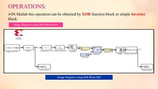
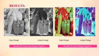
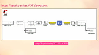
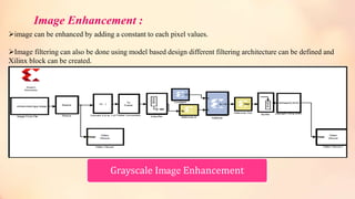
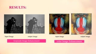
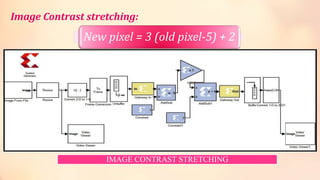
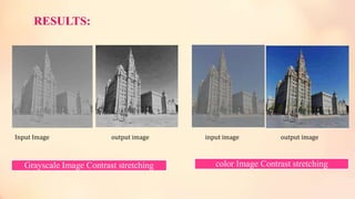
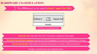
This document discusses high level FPGA modeling for image processing using Xilinx System Generator. It describes how image processing tasks can be implemented using Xilinx System Generator within Simulink. It provides examples of implementing different image processing operations like image negative, enhancement, and contrast stretching. It also describes the hardware co-simulation flow and results showing the input and output images for different operations.
![BY
S.Narendra Achari
[M.TECH-I SEM]
VLSI- SD
DEPARTMENTOF ELECTRONICSAND COMMUNICATION ENGINEERING
ANNAMACHARYAINSTITUTEOFTECHNOLOGY AND SCIENCES::RAJAMPET
(AN AUTONOMOUSINSTITUTION
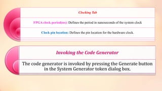
High Level FPGA Modeling for Image Processing Using Xilinx SystemGenerator
A TECHNICAL SEMINAR ON
H.NO:14701D5706](https://image.slidesharecdn.com/narendraachari-150511150351-lva1-app6891/85/Narendra-achari-s-1-320.jpg)