This document contains architectural drawings for a counter design called "Sulthan Gold - Counter Drawing". It includes floor plans, sections, elevations, and details of the counter design. Dimensions and materials to be used are annotated. Standard notes are provided about copyright of the drawings and ensuring dimensions are verified on site before construction.
This document provides an introduction to construction industry and architectural drawing. It discusses the responsibilities of an architect from project planning, design, construction to completion. It also outlines the different types of architectural drawings like presentation drawings, survey drawings, working drawings and their purposes. Finally, it briefly describes the roles of professional bodies in Malaysia that regulate and promote the architecture profession.
Harry Sachdeva Port folio _Documentation_Design_Photoshop_ArchiCAD_Freelancin...Ar.Harry Sachdeva
This document contains architectural drawings for a proposed Indian restaurant including a 3D view, floor plan, set out plan, floor finishes plan, and lighting plan. The drawings provide dimensions and annotations to convey the layout and design of the restaurant interior, including locations of tables, equipment, finishes, and lighting fixtures. General notes indicate that all dimensions must be checked on site and drawings are not for construction until issued.
This document appears to be a portfolio or resume for Shellie Bishoff Gardner that highlights her skills and experience in areas such as drafting and design, interior design, artwork, 3D modeling, and custom design and construction projects. It includes descriptions and images related to residential, commercial, and medical interior design work as well as mechanical drafting, murals, furniture, and more. Contact information is provided at the top and bottom of each page.
*The Nature and Importance of Effective Listening
-The Nature of Listening
-Difference between Hearing and Listening
-The Significance of Listening
-The Process of Listening
*Diverse of Listening
-Types of Listening
-Barriers to Effective Listening
-Some Tips in Effective Listening
This document provides a concept plan and budget for renovating a teen room at a private school. The plan relocates and groups existing furnishings to create distinct areas for activities, games, TV, and meetings while maintaining an open floor plan. Proposed changes include reupholstering some furniture, adding student artwork, a mural, floor pillows, and new TV options. The total proposed budget ranges from $75-100 for artwork to optional amounts for new furniture and a TV.
The document provides specifications for plywood ceiling fins including dimensions of HSS 10x8x5/8 plywood, use of threaded rods, and that CAD files and paper templates will be provided. It includes markings for hole locations to be tapped and notes about joint locations between fins and that numbers are for template and assembly only, not to be included in final fins. Dimensions shown are 10'x10' with maximum 10" varies and material is 3/4" paint grade birch plywood or similar.
This single sentence document provides a scale drawing for a front elevation of 1:1 meters. It conveys essential information about the scale and subject of a technical drawing in only 5 words.
Nasser is an architectural engineer who enjoys creating unique designs. He believes buildings should reflect new ways of thinking. He has a bachelor's degree in architectural engineering and is a member of several professional organizations. Nasser has work experience with architectural firms in Oman and abroad, working on projects ranging from conceptual design to drafting. He is skilled in CAD software, 3D modeling, and rendering. Nasser has received awards for his student project designs of a children's creativity center and vertical village building.
Racquel Fout provides architectural, interior design, and decoration services for residential and commercial projects. She specializes in additions, renovations, and new construction. Her designs maximize space, functionality, and views while incorporating classic and contemporary styles. She works closely with clients on all aspects of a project from concept to completion.
This document provides the user's guide for AutoCAD 2013. It contains information on finding help resources, understanding the user interface, starting and saving drawings, controlling views, organizing drawings and layouts, and customizing the drawing environment. The guide includes over 35 chapters covering all aspects of using AutoCAD 2013. It is copyrighted by Autodesk and cannot be reproduced without permission, except for certain permitted uses.
I:Autocad
is a full featured collection of software tools used for designing and drafting.
Developed by Autodesk, Inc. (Mill Valley, California)
Released in December, 1982
II:Reasons why use Autocad
-Accurate
-Productive and efficient
-Capable of sharing data
III:Drawing Commands
Keystrokes -Commands
l -Line
pl -Polyline
rec -Rectangle
c - Circle
a -Arc
el -Ellipse
pol- Polygon
e -Erase
m -Move
co -Copy
ar -Array
ro -Rotate
tr -Trim
ex- Extend
o- Offset
s -Stretch
mi -Mirror
f -Fillet
cha -Chamfer
J- Join
Br -Break
sc -Scale
po -Point
spl -Spline
la -Layer
mt -Mtext
dim -Dimension
h -Hatch
ch -Properties
lw -Line weight
IV:Entering points in Autocad
-Absolute coordinates
-Relative rectangular coordinates / relative coordinates
-Relative polar coordinates / polar coordinates
V:2 Types of Array
-Rectangular array
-Polar array
VI:Layer properties
-Status
-Name
-On
-Freeze
-Lock
-Color
-Linetype
-Lineweight
-Plot style
-Plot
-Description
VII:Dimension
a.Basic Types:
-Linear
-Angular
-Radial
-Ordinate
-Arc length
b.Parts of Dimension:
-Dimension text
-Dimension line
-Arrowheads
-Extension line
-Center mark
-Center lines
The document provides instructions for creating an A-size prototype drawing in AutoCAD. It discusses the basic AutoCAD interface including tools, menus, and coordinate systems. It then provides a 14 step procedure to draw a border, add offsets for a title block, insert text, and set up layers and linetypes. The goal is to create a template for an A-size drawing with title block and proper layer setup.
The document provides a list of shortcuts for various AutoCAD commands grouped into categories like Blocks, Common Commands, Control Keys, etc. It includes over 250 shortcuts with the corresponding AutoCAD command and a brief comment description for each. Tips are also provided at the end of some sections to provide additional guidance on using certain commands.
3D Drawing discusses different types of perspective drawing techniques and ellipses. There are three main types of perspective drawing: one-point, two-point, and three-point perspective. One-point perspective uses a single vanishing point, two-point uses two vanishing points, and three-point perspective adds complexity with three vanishing points. An ellipse is a circle viewed in perspective, so it follows the same properties as a circle but appears elongated.
The document provides an introduction to AutoCAD, a computer-aided drafting software. It describes AutoCAD as a program used to create precise 2D and 3D drawings for construction and manufacturing. It then discusses the different types of drafters that use AutoCAD, including mechanical, architectural, electrical, and civil drafters. Finally, it provides an overview of the AutoCAD interface and basic tools, how to install AutoCAD, and how to create a simple drawing using basic commands like drawing a horizontal line.
The document provides an overview of a six-week industrial training project on AutoCAD. It discusses the latest version of AutoCAD, the AutoCAD interface and screen, coordinate systems, toolbars, 2D and 3D commands, modeling, and benefits of using AutoCAD. The training was completed at Hi Tech Point Technologies and covered topics like dimensions, blocks, isometric views, and examples of drawings created during the course using various AutoCAD tools and commands.
Introduction To Computer Aided Drafting And DesignHites
This document provides an overview of an introductory computer aided drafting and design (CADD) course. The course aims to develop students' technical drawing and CADD skills through assignments involving sketching, drawing orthographic and pictorial views, and learning AutoCAD basics. Over the course, students will learn to visualize objects from technical drawings, develop CADD skills using computers, and recognize CADD's contributions to industry applications. Assignments will involve sketching and drawing various views, learning about coordinate systems, dimensions, sections and more in AutoCAD.
The
architectural
working drawings.
1.2-1 Site Development Plan or Lot Plan
Site Development Plan or Lot Plan refers to the position and the
location of the building with property line, setbacks, approaches, grade
contours, landscape and other pertinent data in relation to the site.
It shows the following:
1. Property lines with dimensions
2. Setback lines
3. Existing and proposed contours
4. Existing and proposed structures
5. Existing and proposed utilities
6. Existing and proposed roads and walks
7. Existing and proposed landscape features
8. North arrow
9. Scale
10. Legend
This document provides an overview of AutoCAD, including:
- Definitions of CAD, CADD, and AutoCAD and how AutoCAD is the largest selling CAD software used worldwide.
- Details on the version history and releases of AutoCAD from 1982 to present.
- Descriptions of the scope of AutoCAD applications across various engineering fields.
- Explanations of the advantages of AutoCAD over manual drafting, including speed, accuracy, flexibility and enhanced visualization.
- An overview of the graphical user interface of AutoCAD and the main screen areas like the drawing area, UCS icon, crosshairs, menus and toolbars.
Short Presentation (2 Hrs) on SSL and TLS Protocol and its reference standard. Good for intermediate participant or technical who want to understand secure protocol an
This document defines common abbreviations used for floor levels in construction drawings: SSL refers to the structural slab level, SFL is the structural floor level, and FFL stands for the finish floor level. It provides examples of how these abbreviations may be used on structural versus architectural drawings and notes that rooms often require concrete fill to reach the finish floor level, while structural slab and floor levels are usually the same in parking areas.
AutoCAD Workbook packed with over 200 exercises to enable you practice until you become an expert. The book does not contain any text, just pure exercises to enable you practice and practice. Get a copy today. https://gumroad.com/l/sxXqs
This document provides an overview of the 3D modeling interface and tools in AutoCAD. It describes how to set up the 3D modeling workspace and viewports, visualize 3D models using techniques like hiding lines and adjusting visual styles, work with the z-axis and user coordinate system, and create basic 3D objects. The tutorial is divided into chapters that cover these essential 3D modeling concepts and commands.
This document contains a site plan for IS 252K located at 1084 Lenox Road in Brooklyn, New York. It shows the location of the existing 4-story masonry building on the lot, along with various site features like yards, sidewalks, and fences. It also includes a key plan showing the location of the site in relation to the surrounding streets.
The document contains architectural drawings showing sections and details of proposed building foundations and structures. It includes 5 sections and 2 details of foundations, showing elements like rubble masonry walls, isolation joints, ground floor slabs, sand and polythene layers. It also provides notes on dimensions, materials, specifications, and abbreviations. The scale of the drawings ranges from 1:5 to 1:30.
The document is a set of architectural drawings for a proposed redevelopment project. It includes a cover sheet listing 18 drawings related to site context, existing conditions, and proposed plans, elevations and sections. The drawings document the existing buildings and site conditions, including dimensions of the various shops on the ground floor.
This document is a set of site plans for expanding the garden center at a Lowe's store in Carmel, Indiana. The existing garden center measures 42,199 square feet and the proposed expansion will add 17,225 square feet for a new total of 59,424 square feet. The plans show the layout of the existing store and parking lot as well as the proposed expansion area. Dimensions and notes provide information on setbacks, parking requirements, references used, and work to be done.
This document contains architectural drawings and details for a private house designed by Salma Mahgoub. It includes a site plan, basement floor plan, ground floor plan, and second floor plan. The drawings show the layout and dimensions of the rooms. Salma contributed to the project by drafting it in ArchiCAD 16 software and assisting with plan development while completing a job training program in 2015. The status of the project is listed as under construction.
This document contains drawings and details for the proposed head office of ZeePay Ghana Limited located in Cantonements, Accra. It includes architectural site plans, block plans, fence details, floor plans for each level, elevations of the building, and lists of consultants involved in the project including the designers, engineers, and contractors.
The document contains engineering drawings for the layout and design of a Domino's Pizza store. It includes floor plans showing the placement of fixtures, furniture and equipment. It also includes drawings for lighting layout, electrical plans showing outlet locations, plumbing diagrams for water and drainage, and specifications for materials. The drawings are technical documents intended to guide the construction and outfitting of the new pizza store according to the designer's intentions.
This document provides information for a McDonalds refurbishment project including a stair survey, design specifications, balustrade specifications, pricing sheet, and quotation. It outlines the scope of design work including 3D modeling, general arrangement drawings, fabrication drawings, glass drawings, and other deliverables. Pricing and timelines are provided for the design work. Upon starting the project, the document instructs setting up the project folder and OneNote template using existing templates.
Farmers Executive Fitness Wilshire Blvd LA CARichard Clark
This document provides plans and specifications for tenant improvements to convert part of the second floor of an existing building into a corporate fitness center for Farmers Insurance. The project involves remodeling approximately 3,470 square feet on the second floor with new partitions, flooring, fixtures and equipment. Drawings include floor plans, elevations, sections and details. Specifications are provided for mechanical, electrical and plumbing work. The project will add 35 new occupants to the second floor without exceeding egress requirements.
Working drawing of the civil engineering building, Faculty of Engineering, Ta...Ahmed El Ashry
This document contains an architectural drawing cover sheet with general notes and symbols. It includes information such as the project name, location, date, drawing list, revisions, and sheet index. It also contains several sections including general notes with instructions for contractors, abbreviations, architectural symbols, and standard hatch patterns. The cover sheet provides essential information for the architectural drawings and sets standards and requirements for construction.
This document contains floor plans and details for an ideal classroom layout. The floor plan shows the layout of furniture including desks, tables, and storage units. It also indicates the location of doors, windows and other fixtures. The millwork details provide close-up views and dimensions of custom cabinetry, countertops and other built-in elements. Notes provide specifications for materials, finishes, and construction of the millwork components.
This document contains a drawing list for a building project. It includes the titles of 16 drawings, their numbers, and the names of the people who drew them. The drawings include site plans, floor plans, elevations, and schedules for doors and windows. The list also notes the scales of some of the drawings.
This document contains a section drawing of an apartment building showing floor levels and room layouts. The section cuts through the master bedroom, kitchen/dining room, and living room. It includes notes that the drawing is not to scale and all dimensions must be checked on site before work begins.
This document contains construction plans and specifications for remodeling a residential property located at 13907 Burton Street in Panorama City, CA. It includes three phases of construction work involving remodeling of bathrooms and other interior spaces, adding exterior decks and windows, and eventually installing a pool, jacuzzi, and surrounding patio area. The document provides details on the project scope, building design team, permits, phases of construction, and notes for contractors. Dimensions and details are included on the floor plans and construction drawings.
This document appears to be a landscape architect's portfolio and resume. It includes sections about the individual's education, work experience, workshop experience, skills, and references. It highlights a Bachelor's degree in landscape architecture and over 5 years of experience working as a landscape architect and drafter. The portfolio also includes pictures and descriptions of 5 design projects ranging from single-family residences to urban developments.
Item vi.a. doyle street mews pc 09 28-2017E'ville Eye
This document provides information about bike parking and unit areas for a 6-unit residential development. It states that there will be 8 indoor bike racks for units 1, 2, 4, and 5, and 2 indoor bike racks for units 3 and 6, along with 4 outdoor guest bike racks for a total of 14 bike racks on site. The total floor area for the 6 units is 9,964 square feet. Each unit is described as having either 3 bedrooms and 3.5 bathrooms with a bonus room, or 3 bedrooms and 2.5 bathrooms with a bonus room. An open space area tabulation is also provided showing the private and common open space areas.
The document provides details for joinery in laboratories and kitchenettes, including notes, dimensions, and diagrams. Key information includes:
1. Dimensions are to be checked on site and this section read with other schedules. Typical details include laminate finishes, concealed hinges and locks, adjustable shelves, and recessed edges.
2. Diagrams show layouts for typical kitchenettes and labs, including locations of sinks, appliances, and storage cabinets. Lockable cabinets and drawers are indicated.
3. Additional notes specify materials like compact laminate benchtops and splashbacks, coved skirting, seals, and accessories to be installed.
The document summarizes the proposed construction of a 2-storey terrace house in Bandar Bukit Raja, Selangor, Malaysia. It includes site plans, floor plans, elevations, and tender documents. The tender documents provide instructions to tenderers, conditions of tendering, a final summary of tender costs, and appendices with schedules of finishes, day work rates, material prices, and forms for the earnest money and performance bonds. The objective is to invite qualified contractors to submit tenders with all necessary details for the proposed construction project.
The document summarizes the proposed construction of a 2-storey terrace house in Bandar Bukit Raja, Selangor, Malaysia. It includes site plans, floor plans, elevations, and tender documents. The tender documents provide instructions to tenderers, conditions of tendering, a final summary of tender costs, and appendices with schedules of finishes, day work rates, material prices, and forms for the earnest money and performance bonds. The goal is to invite competitive tenders for the construction project from qualified contractors and ensure transparency in the tendering process.
Interior Design Plan of Living Room-Kitchen of 1BHK Apartment in Delhiby Contractorbhai.com team. This file comprises plan details for Living Room and Kitchen .
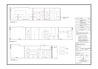
3. SECTION B - B
LVL
+ 15.00 CM
LVL
0.00 CM
BACK DISPLAY PLAN
eq eq eq eq eq eq eq eq eq eq eq eq eq eq eq eq
546
30
A
A
C
B
60
70
20
70
THIS DESIGN / DRAWING IS A PROJECT OF SUKUDASS
ARCHITECTS.IT IS SUBJECT TO THEIR RECALL AND
MUST NOT BE USED, COPIED/REPRODUCED WITH OUT
THEIR PERMISSION.
ALL DIMENSIONS ARE IN CENTIMETERS.
ALL DIMENSIONS TO BE CHECKED AT SITE.
NO DIMENSIONS TO BE SCALED FROM THE DRAWINGS.
ONLY WRITTEN DIMENSIONS TO BE FOLLOWED.
IN THE EVENT OF ANY DISCREPANC1ES OR
DIFFERENCE BETWEEN DRAWINGS OR SITE
CONDITIONS IMMEDIATE REFERENCE IS TO BE
MADE TO BE EXECUTION OF WORK AT SITE.
LEVELS MENTIONED AS PER PROPOSED LEVELS.
PROJECT
DATE
DRAWING TITLE
SULTHAN GOLD
SHEET
SHAJAS
SULTHAN GOLD - COUNTER DRAWING
1:25
PROJECT NO. : 220
WDRG / 221 / 02 / R0
DRG NO. : 02 SCALE
DRAWN
26.04.2014
NORTH CHECKED
SUKUDASSARCHITECTS
REGD OFFICE: M 31, CHANGAMPUZHA NAGAR, KOCHI 682033, KERALA, INDIA
TELE- FAX: +91.484.2542488
E MAIL: INFO@SUKUDASSARCHITECTS.COM
WEB: WWW.SUKUDASSARCHITECTS.COM
A2
A
BB
C
C
D
D
3
24
3
4. SECTION A - A
THIS DESIGN / DRAWING IS A PROJECT OF SUKUDASS
ARCHITECTS.IT IS SUBJECT TO THEIR RECALL AND
MUST NOT BE USED, COPIED/REPRODUCED WITH OUT
THEIR PERMISSION.
ALL DIMENSIONS ARE IN CENTIMETERS.
ALL DIMENSIONS TO BE CHECKED AT SITE.
NO DIMENSIONS TO BE SCALED FROM THE DRAWINGS.
ONLY WRITTEN DIMENSIONS TO BE FOLLOWED.
IN THE EVENT OF ANY DISCREPANC1ES OR
DIFFERENCE BETWEEN DRAWINGS OR SITE
CONDITIONS IMMEDIATE REFERENCE IS TO BE
MADE TO BE EXECUTION OF WORK AT SITE.
LEVELS MENTIONED AS PER PROPOSED LEVELS.
PROJECT
DATE
DRAWING TITLE
SULTHAN GOLD
SHEET
SHAJAS
SULTHAN GOLD - COUNTER DRAWING
1:25
PROJECT NO. : 220
WDRG / 221 / 02 / R0
DRG NO. : 02 SCALE
DRAWN
26.04.2014
NORTH CHECKED
SUKUDASSARCHITECTS
REGD OFFICE: M 31, CHANGAMPUZHA NAGAR, KOCHI 682033, KERALA, INDIA
TELE- FAX: +91.484.2542488
E MAIL: INFO@SUKUDASSARCHITECTS.COM
WEB: WWW.SUKUDASSARCHITECTS.COM
A2
LVL
0.00 CMeq eq eqeq eq eq eq eq eq eq
check
at site
eq eq eq eq eq eq eq eq eq eq
check
at site
35
80
60
175
COUNTER PLAN
LVL
+ 15.00 CM
A
C
B
33.84
AA
BB
C
C
D
D
5. ELEVATION SIDE B
LVL 0.00 CM
LVL 15.0 CM
ELEVATION SIDE C
LVL 0.00 CM WOODEN FLOORING
19 MM PLY WITH
HIGH GLOSS
BLACK LAMINATE
PROFILE HANDLE
ENOX ( EAPS - 049 )
8 MM GLASS WITH
EDGE POLISHED
BAFFLE CEILING IN
BLACK COLOR
( HUNTER DOUGLOUS )
THIS DESIGN / DRAWING IS A PROJECT OF SUKUDASS
ARCHITECTS.IT IS SUBJECT TO THEIR RECALL AND
MUST NOT BE USED, COPIED/REPRODUCED WITH OUT
THEIR PERMISSION.
ALL DIMENSIONS ARE IN CENTIMETERS.
ALL DIMENSIONS TO BE CHECKED AT SITE.
NO DIMENSIONS TO BE SCALED FROM THE DRAWINGS.
ONLY WRITTEN DIMENSIONS TO BE FOLLOWED.
IN THE EVENT OF ANY DISCREPANC1ES OR
DIFFERENCE BETWEEN DRAWINGS OR SITE
CONDITIONS IMMEDIATE REFERENCE IS TO BE
MADE TO BE EXECUTION OF WORK AT SITE.
LEVELS MENTIONED AS PER PROPOSED LEVELS.
PROJECT
DATE
DRAWING TITLE
SULTHAN GOLD
SHEET
SHAJAS
SULTHAN GOLD - COUNTER DRAWING
1:25
PROJECT NO. : 220
WDRG / 221 / 02 / R0
DRG NO. : 02 SCALE
DRAWN
26.04.2014
NORTH CHECKED
SUKUDASSARCHITECTS
REGD OFFICE: M 31, CHANGAMPUZHA NAGAR, KOCHI 682033, KERALA, INDIA
TELE- FAX: +91.484.2542488
E MAIL: INFO@SUKUDASSARCHITECTS.COM
WEB: WWW.SUKUDASSARCHITECTS.COM
A2
DETAIL - A
DETAIL - B
6. SECTION D - D
50
10
SECTION C - C
50
10
20
80
50
10
60
15
5
5
5
5
5
eq
eq
eq
eq
228
INSIDE PAINT FINISH
19 MM PLY WITH
BLACK HIGH GLOSS
LAMINATE FINISH
SKIRTING
8 MM GLASSWITH
EDGE POLISHED
SOLD SURFACE
8 MM GLASS WITH
D CLAMP
ELEVATION SIDE A
12 MM PLY WITH
WHITE LAMINATE
FINISH OF 5 CM THICK
STEEL FINISH
OF 3 CM THICK
SPOT LIGHT
PROFILE HANDLE
ENOX EAPS - 049
SKIRTINGLVL 15.0 CM
WOODEN FLOORING
19 MM PLY WITH
HIGH GLOSS
BLACK LAMINATE
65
2.5
2.5
70
120
190
THIS DESIGN / DRAWING IS A PROJECT OF SUKUDASS
ARCHITECTS.IT IS SUBJECT TO THEIR RECALL AND
MUST NOT BE USED, COPIED/REPRODUCED WITH OUT
THEIR PERMISSION.
ALL DIMENSIONS ARE IN CENTIMETERS.
ALL DIMENSIONS TO BE CHECKED AT SITE.
NO DIMENSIONS TO BE SCALED FROM THE DRAWINGS.
ONLY WRITTEN DIMENSIONS TO BE FOLLOWED.
IN THE EVENT OF ANY DISCREPANC1ES OR
DIFFERENCE BETWEEN DRAWINGS OR SITE
CONDITIONS IMMEDIATE REFERENCE IS TO BE
MADE TO BE EXECUTION OF WORK AT SITE.
LEVELS MENTIONED AS PER PROPOSED LEVELS.
PROJECT
DATE
DRAWING TITLE
SULTHAN GOLD
SHEET
SHAJAS
SULTHAN GOLD - COUNTER DRAWING
1:25
PROJECT NO. : 220
WDRG / 221 / 02 / R0
DRG NO. : 02 SCALE
DRAWN
26.04.2014
NORTH CHECKED
SUKUDASSARCHITECTS
REGD OFFICE: M 31, CHANGAMPUZHA NAGAR, KOCHI 682033, KERALA, INDIA
TELE- FAX: +91.484.2542488
E MAIL: INFO@SUKUDASSARCHITECTS.COM
WEB: WWW.SUKUDASSARCHITECTS.COM
A2
19 MM PLY
WOODEN
REEPER
OF 1 X 1 CM
8 MM GLASS
EDGE
POLISHED
DETAIL - D
10 MM PLY
IN WHITE
LAMINATE
FINISH
5
LIGHT FIXTURES
3 X 3 CM
STEEL PIPE
IN MAT FINISH
SCREW
ROOF
3 X 3 CM
STEEL PIPE
IN MAT FINISH
DETAIL - A DETAIL - B
DETAIL - C
8 MM GLASS
EDGE
POLISHED
D - CLAMP
DETAIL - C
DETAIL - D
7.
8.
9.
10.
11.
12.
13.
14.
15. Glass OpeningsGlass Openings Glass Openings
Exposed brick cladding
UP
STORAGE UNIT UNDER STAIR
TOILET
110 X 230
NORTH
RESIDENCE OF ABDUL HAFEEZ - INTERIOR LAYOUT
OPTION - 2
PROJECT
DATE
DRAWING TITLE
INTERIOR FOR ABDUL HAFEEZ RESIDENCE
SHAJAS
SHEET
REVISED INTERIOR LAYOUT
1:100
PROJECT NO. : 260
CDRG / 260 / 01 / R1
DRG NO. : 01 SCALE
DRAWN
04.10.2013
CHECKED
SUKUDASSARCHITECTS
REGD OFFICE: M 31, CHANGAMPUZHA NAGAR, KOCHI 682033, KERALA, INDIA
TELE- FAX: +91.484.2542488
E MAIL: INFO@SUKUDASSARCHITECTS.COM
WEB: WWW.SUKUDASSARCHITECTS.COM
A3
FIRST BASEMENT FLOOR PLAN
SECOND BASEMENT FLOOR PLAN
UP
DN
D
D2
D
LIFT
130 X 140
D2
1. FAMILY LIVING
2. LIFT
3. BEDROOM
4. TOILET
5. BALCONY
6. DRESS1
2
3
3
6
4
5
4
6
16. PROJECT
DATE
DRAWING TITLE
INTERIOR FOR ABDUL HAFEEZ RESIDENCE
SHAJAS
SHEET
REVISED INTERIOR LAYOUT
1:100
PROJECT NO. : 260
CDRG / 260 / 01 / R1
DRG NO. : 01 SCALE
DRAWN
04.10.2013
NORTH CHECKED
SUKUDASSARCHITECTS
REGD OFFICE: M 31, CHANGAMPUZHA NAGAR, KOCHI 682033, KERALA, INDIA
TELE- FAX: +91.484.2542488
E MAIL: INFO@SUKUDASSARCHITECTS.COM
WEB: WWW.SUKUDASSARCHITECTS.COM
A3
GROUND FLOOR PLAN
DN
UP
D
D2
D
D2 D
D2
RESIDENCE OF ABDUL HAFEEZ - INTERIOR LAYOUT
OPTION - 2
D3
1. SITOUT
2. FORMAL LIVING
3. LADIES SITTING
4. LIFT
5. BED ROOM
6. TOILET
7. DINING AREA
8. BEDROOM
9. WASH
10. PANTRY
11. TOILET
12. WORK AREA
13. UTILITY
14. STORE
1
2
3
7
4
5
6 1
9
11
1314
8
10
12
17. FIRE IN THE BELLY RESTAURANT IN NILA
AC RESTAURANT - CEILING LAYOUT ( CANDLE )
THIS DESIGN / DRAWING IS A PROJECT OF SUKUDASS
ARCHITECTS.IT IS SUBJECT TO THEIR RECALL AND
MUST NOT BE USED, COPIED/REPRODUCED WITH OUT
THEIR PERMISSION.
ALL DIMENSIONS ARE IN CENTIMETERS.
ALL DIMENSIONS TO BE CHECKED AT SITE.
NO DIMENSIONS TO BE SCALED FROM THE
DRAWINGS.
ONLY WRITTEN DIMENSIONS TO BE FOLLOWED.
IN THE EVENT OF ANY DISCREPANC1ES OR
DIFFERENCE BETWEEN DRAWINGS OR SITE
CONDITIONS IMMEDIATE REFERENCE IS TO BE
MADE TO BE EXECUTION OF WORK AT SITE.
LEVELS MENTIONED AS PER PROPOSED LEVELS.
PROJECT
DRAWING TITLE
DATE
SHAJAS
SHEET
1:50
PROJECT NO. : 244
WDRG / 244B / 37 / R0
DRG NO. : 37 SCALE
DRAWN
24.12.2013
NORTH CHECKED
SUKUDASSARCHITECTS
REGD OFFICE: M 31, CHANGAMPUZHA NAGAR, KOCHI 682033, KERALA, INDIA
TELE- FAX: +91.484.2542488
E MAIL: INFO@SUKUDASSARCHITECTS.COM
WEB: WWW.SUKUDASSARCHITECTS.COM
A3
SECTION B - B
CEILING HEIGHTS ARE CHANGED
SECTION A - A
A A
B
B
2 CM DIA
WOODEN PIECE
OR MDF
5 MM DIA HOLE
FOR WIRES
CANDLE
TOP VIEW
2 CM DIA
WOODEN PIECE
OR MDF
2 MM DIA HOLE
FOR LED LIGHT
CANDLE
BOTTOM VIEW
5 MM DIA HOLE
IN TOP
ELECTRIC WIRE
THROUGH HOLE
2 MM DIA
HOLE IN BOTTOM
LED LIGHT
ISOMETRIC VIEW ISOMETRIC VIEW ( CANDLE )
REFLECTED CEILING PLAN
2 CM DIA
WOODEN PIECE
OR MDF
ALUMINIUM OR
MS PLATE SCREWED
WITH WOODEN CANDLE
MS PLATE & WOODEN
CANDLE SCREWED WITH
CEILING
CEILING
FIXING DETAIL
1.5 CM DIA
MS PLATE SCREWED WITH
WOODEN CANDLE
MS PLATE & WOODEN
CANDLE SCREWED
WITH CEILING
FIXING DETAIL PLAN
GRID
OF 20 X 20 CM
2 CM DIA
WOODEN PIECE
OR MDF
HOLE FOR WIRE
LED
CANDLE DETAIL & SIZES
10
8
6
6
2 2 2 2
18. FIRE IN THE BELLY RESTAURANT IN NILA
AC RESTAURANT - GRAPHICS DETAIL
THIS DESIGN / DRAWING IS A PROJECT OF SUKUDASS
ARCHITECTS.IT IS SUBJECT TO THEIR RECALL AND
MUST NOT BE USED, COPIED/REPRODUCED WITH OUT
THEIR PERMISSION.
ALL DIMENSIONS ARE IN CENTIMETERS.
ALL DIMENSIONS TO BE CHECKED AT SITE.
NO DIMENSIONS TO BE SCALED FROM THE DRAWINGS.
ONLY WRITTEN DIMENSIONS TO BE FOLLOWED.
IN THE EVENT OF ANY DISCREPANC1ES OR
DIFFERENCE BETWEEN DRAWINGS OR SITE
CONDITIONS IMMEDIATE REFERENCE IS TO BE
MADE TO BE EXECUTION OF WORK AT SITE.
LEVELS MENTIONED AS PER PROPOSED LEVELS.
PROJECT
DRAWING TITLE
DATE
SHAJAS
SHEET
1:75
PROJECT NO. : 244
WDRG / 244B / 39 / R0
DRG NO. : 39 SCALE
DRAWN
28.12.2013
NORTH CHECKED
SUKUDASSARCHITECTS
REGD OFFICE: M 31, CHANGAMPUZHA NAGAR, KOCHI 682033, KERALA, INDIA
TELE- FAX: +91.484.2542488
E MAIL: INFO@SUKUDASSARCHITECTS.COM
WEB: WWW.SUKUDASSARCHITECTS.COM
A3
A
CEILING HEIGHTS ARE CHANGED
70
90
A
SIDE B ELEVATION
B
A
SIDE A ELEVATION SECTION A - A
SCALED
EQ
EQ
90
CHECK
AT SITE
DETAIL - A
DETAIL - B
DETAIL - A
KARIMPANA
WOOD
STEEL STUD
5 MM ACRYLIC SHEETS
GRAPHICS BETWEEN
ACRYLIC SHEETS
KARIMPANA
WOOD
5 MM ACRYLIC SHEETS
GRAPHICS BETWEEN
ACRYLIC SHEETS
DETAIL - B
PLAN
CORNER VIEW
ISOMETRIC VIEW
10 10
70
90
10 10
70
90
10 10
70
90
10 10
70
90
10 10
19. 3
3
6
KARIMPANA WOOD
OF 3 CM THICK
2.5 X 2.5 CM
MS SQUARE PIPE
CONCRETE BED
SS PLATE
2.5 X 2.5 CM
MS SQ.PIPE
DETAIL - A
DETAIL - B
DETAIL - C
A
120
90
A
B B
79
3 3
90
3
55
55
120
PLAN PLAN WITH MS FRAME WORK
C:Documents and SettingsOfficeDesktopCEILING IMAGE 1 .jpg
C:Documents and SettingsOfficeDesktopAC TABLE .jpg
CEILING WITH MS FRAME VIEW
TABLE WITH MS FRAME VIEW
20
2.5 X 2.5 CM
MS SQ. PIPE
BHAVANI - AC RESTAURANT TABLE
THIS DESIGN / DRAWING IS A PROJECT OF SUKUDASS
ARCHITECTS.IT IS SUBJECT TO THEIR RECALL AND
MUST NOT BE USED, COPIED/REPRODUCED WITH OUT
THEIR PERMISSION.
ALL DIMENSIONS ARE IN CENTIMETERS.
ALL DIMENSIONS TO BE CHECKED AT SITE.
NO DIMENSIONS TO BE SCALED FROM THE DRAWINGS.
ONLY WRITTEN DIMENSIONS TO BE FOLLOWED.
IN THE EVENT OF ANY DISCREPANC1ES OR
DIFFERENCE BETWEEN DRAWINGS OR SITE
CONDITIONS IMMEDIATE REFERENCE IS TO BE
MADE TO BE EXECUTION OF WORK AT SITE.
LEVELS MENTIONED AS PER PROPOSED LEVELS.
PROJECT
DATE
DRAWING TITLE
FIRE IN THE BELLY RESTAURANT IN NILA
SHEET
SHAJAS
AC RESTAURANT - TABLE DRAWING
1:100
PROJECT NO. : 244
WDRG / 244B / 24 / R0
DRG NO. : 24 SCALE
NORTH DRAWN
14.10.2013
CHECKED
A3
SUKUDASS ARCHITECTS
REGD OFFICE: M 31, CHANGAMPUZHA NAGAR, KOCHI 682033, KERALA, INDIA
TELE- FAX: +91.484.2542488
E MAIL: INFO@SUKUDASSARCHITECTS.COM
WEB: WWW.SUKUDASSARCHITECTS.COM
ELEVATION SECTION B - BSECTION A - A
75
246
KARIMPANA
OF 3 CM THICK
2.5 X 2.5 CM
MS SQUARE PIPE
17.5
75
246
2.5 X 2.5 CM
MS SQ.PIPE
KARIMPANA
OF 3 CM THICK
DETAIL - A
DETAIL - B
DETAIL - C
100100
CEILING