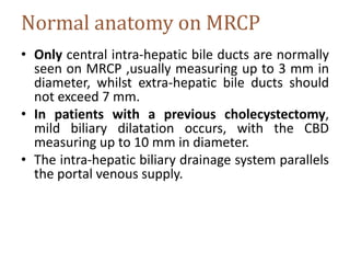
Magnetic resonance
cholangiopancreatography
Dr. Mahmoud Abdel Aziz
National Liver Institute
Normal Anatomy of the Biliary Tree &
Gallbladder
• The individual biliary drainage system is
parallel to portal venous supply.
• The right hepatic duct has two major
branches: a posterior branch draining the
posterior segments (VI and VII), with an
almost horizontal course, and an anterior
branch draining the anterior segments (V and
VIII), with a more vertical course.
• The right posterior duct usually runs posterior
and fuses with the right anterior duct to form
the right hepatic duct.
• The left hepatic duct is formed by segmental
tributaries draining segments II–IV.
• The bile duct draining the caudate lobe usually
joins the origin of the left or right hepatic duct
• The common hepatic duct is the portion of the
bile duct above the cystic duct and below the
bifurcation.
• It is formed by fusion of the right hepatic duct
and the left hepatic duct, they usually join up
just outside the porta hepatis (±1 cm below
the edge of the liver).
Gallbladder
• The gallbladder is a pear shaped hollow viscus
located in a fossa on the lower surface of the
liver, between the right lobe and the quadrate
lobe.
• It usually measures 10 cm in length, with a
diameter ranging from 3 to 5 cm, and its wall
is less than 3 mm thick.
• The gallbladder is divided into four parts: the
fundus, usually projects beyond the inferior
border of the liver; the body, which is the part
in contact with the second portion of the
duodenum and the colon; the infundibulum,
or Hartmann’s pouch, located at the free edge
of the lesser omentum bulging toward the
cystic duct; and the neck, which is the part
between the body and the cystic duct.
• The gallbladder wall has low signal intensity
on T2-weighted images, intermediate signal
intensity on T1-weighted images, and is
enhanced uniformly after the administration
of gadolinium-based contrast material.
Normal bile appears uniformly bright on T2-
weighted sequences, while on T1-weighted
images it varies greatly in signal intensity
depending on its concentration
• The cystic duct connects the gallbladder to the
extra-hepatic bile duct and its point of
insertion into the extra-hepatic bile duct
marks the division between the common
hepatic duct and the common bile duct.
• The cystic duct usually measures 2–4 cm in
length, with a diameter ranging from 1 to 5
mm, and it contains prominent concentric
folds known as spiral valves of Heister
• The cystic duct usually joins the common
hepatic duct. The insertion of the cystic duct
into the hepatic duct can be demonstrated
with routine T2-weighted imaging, and MRCP.
• The common bile duct is the portion above
the papilla and below the cystic duct; it has a
mean diameter of 5 mm for patients up to the
age of 50 years, and increases 1 mm per
decade thereafter.
• The course of the normal common bile duct is
through the pancreatic parenchyma (65% of
patients), in a groove in the posterior aspect
of the pancreatic head (25% of patients), and
posterior to the pancreatic head and totally
extrapancreatic (10% of patients). If the distal
common bile duct courses through the
pancreatic parenchyma, it may be smaller in
diameter than the suprapancreatic portion.
• The main pancreatic duct usually measures
9.5–25 cm in length, with maximal
anteroposterior diameters of the head, body
and tail of 3.5 mm, 2.5 mm and 1.5 mm,
respectively.
• It terminates at the major papilla in the
duodenum. This principal duct drains the
greater part of the gland.
• Only a small upper anterior part of the head
uses the accessory pancreatic duct (of
Santorini), which enters the duodenum at the
small accessory papilla .
• The accessory duct usually communicates
with the main pancreatic duct within the head
of the pancreas.
• The pancreatic and common bile ducts join
within the wall of the duodenum and have a
short common terminal portion, which usually
measures 2–15 mm (mean 5 mm) in length. In
some cases, each duct has its own opening at
the papilla.
• The slightly dilated distal segment of the
common channel is also called the ampulla.
Anatomical Variants
Right bile duct Variants(Choi et al., Benson et al)
Huang et al. classification. Right hepatic duct divided into five types
according to sectoral bile drainage and its respective frequencies
Left bile duct Variants(Choi et al., Benson et al)
Huang et al. classification. Left hepatic duct divided into six types according
to segmental bile drainage and its respective frequencies
Cystic duct variant
Different anatomical variants of the cystic duct insertion according to the Benson and Page
classification. (A) Long cystic duct with low fusion with the common hepatic duct. (B)
Abnormally high fusion of the cystic duct with the common hepatic duct (trifurcation). (C)
Presence of an accessory hepatic duct. (D) Abnormal insertion of the cystic duct into the right
hepatic duct. (E) Presence of a cholecystohepatic duct
Pancreatic Divisum
• Represents a variation in pancreatic ductal
anatomy that can be associated with
abdominal pain and idiopathic pancreatitis.
• It is characterized, in the majority of cases, by
the dorsal pancreatic duct (i.e. main
pancreatic and Santorini ducts) directly
entering the minor papilla with no
communication with the ventral duct (duct of
Wirsung) and the major papilla.
Reverse pancreas divisum has been described where the main duct fuses
with the ventral duct and a small residual dorsal duct does not communicate
with the main duct and drains separately into the minor papilla
Three subtypes are known:
o type 1 (classic): no connection at all; occurs in the majority of cases; 70%
o type 2 (absent ventral duct): minor papilla drains all of pancreas while major
papilla drains bile duct; 20-25%
o type 3 (functional): filamentous or inadequate connection between dorsal and
ventral ducts; 5-6%
Annular pancreas
• Is a morphological anomaly that results in pancreatic tissue completely
or incompletely encircling the duodenum. This condition can cause
duodenal obstruction.
Annular pancreas (axial & MIP images)
MRCP
• MRCP Is a non invasive imaging technique to
visualize intra & extra-hepatic biliary tree as
well as the pancreatic ductal system.
• It can provide diagnostically-equivalent
images to ERCP and is a useful technique in
high risk patients to avoid significant
morbidity.
• It uses MR imaging to visualize fluid in the
biliary and pancreatic ducts as high signal
intensity on T2 weighted sequences.
• By using heavily T2 weighted sequences, the
signal of static or slow-moving fluid-filled
structures such as the bile and pancreatic
ducts is greatly increased, resulting in
increased duct-to-background contrast.
PREPARATION
• Patients are fasted for 4 h prior to the study in
order to reduce fluid secretions within the
stomach and duodenum, reduce bowel
peristalsis and promote gallbladder distension.
We do not routinely use an anti-peristaltic
agent.
• No exogenous contrast medium is
administered to the patient.
• Ask the patient to remove all metallic objects.
TECHNIQUE
• All protocols obtain heavily T2-weighted
sequences.
• Most commonly obtained sequences are:
– RARE: rapid acquisition and relaxation enhancement
– FRFSE: fast-recovery fast spin-echo coronal oblique 3D
respiratory triggered
– HASTE: half-Fourier acquisition single shot turbo spin
echo-axial 2D breath hold sequence which provides
superior images and can be performed in single
breath hold (<20 s) and a fat-suppressed sequence
• An additional sequence that can be acquired
to evaluate the duct wall is a fat suppressed
T1 GRE sequence.
• For optimal visualization of ducts, acquired
images are reformatted in different planes
using Multiplanar reconstruction (MPR) and
Maximum intensity projection (MIP).
Technique of acquisition
• Breath hold: should infrom patient to stop
breathing when hearing the radiographer voice on
headphone
• No breath hold technique (respiratory
triggering): the respiratory bellows should be
positioned at the point of the maximum rise and fall
in the patient chest and observe the respiratory wave
form that appears on the operator console.
Patient Position
• Patient lies supine with head pointing toward the
magnet.
• Place the body coil over the upper abdomen.
• Securely tighten the body coil to reduce respiratory
artifact.
• Localizer:
– Three plane localizer intinally taken to localize and
plane the sequences
• T2 fat saturation 4 mm breath hold (coronal):
– Plan the coronal slices on the axial localizer.
– Place the block over the liver as shown.
– Slices must be sufficent to involve entire the liver
from anterior to posterior.
• T2 weighted breath hold (axial)/Fat
saturation:
– Plane the axial slices on the coronal images.
– Place the block across over the liver as shown.
– Slices must cover entire the biliary tree from the
diaphragm down the C loop of the duodenum.
a two-dimensional (2D), heavily T2-weighted, fat-suppressed, breath-hold
sequence. This sequence can provide single thick-slab images with slice
thicknesses ranging from 10 to 70 mm and multiple thin-slab images with
slice thicknesses ranging from 2 to 5 mm
• T2 weighted HASTE breath hold coronal
oblique:
– Put the coronal oblique thick slab on the axial
HASTE.
– Position the block across the CBD and rotate the
block 20-30 degree clock wise to include the CBD
and GB.
• 3D T2 turbo spin echo coronal with
respiratory triggering:
– Put the coronal 3D on the axial HASTE.
– Position the block across the CBD , should include
the CBD , pancreatic duct & GB.
Technical modifications
• Secretin-stimulated MRCP.
• Functional MR cholangiography.
• Negative oral contrast agent to (null) the
duodenum: by commercially available agents
or natural products reach in manganse
(pineapple) …. Shorten T2 relaxation time and
reduce T2 signal from bowel.
Secretin-stimulated MRCP
• Secretin is an endogenous hormone normally
produced by the duodenum, which stimulates
exocrine secretion of the pancreas. When
given as a synthetic agent intravenously
(1 ml/10 kg body weight), it improves the
visualization of the pancreatic duct by
increasing its caliber.
• We perform a thick slab MRCP in the coronal
oblique plane at baseline and then at 1, 3, 5,
7 and 9 min following injection. Its effect
starts almost immediately and peaks between
2 to 5 mins. By 10 min, the caliber of the main
pancreatic duct should return to baseline
with persistent dilatation of >3 mm
considered abnormal.
• The indications for this technique:
– Detection and characterization of pancreatic
ductal anomalies and strictures.
– Characterisation of any communication between
the pancreatic duct and pseudocysts/pancreatic
fistulas.
– Assessment of pancreatic function and sphincter
of Oddi dysfunction.
Example of a normal secretin-stimulated MRCP in a patient being investigated for
sphincter of Oddi dysfunction, with idiopathic dilatation of the CBD. A) The
pancreatic duct is of normal caliber (arrow) with little secretions in the duodenum
(D); b) at 3 min there is progressive filling of the duodenum (D) due to an increase
in pancreatic secretions and the pancreatic duct has become more prominent
(arrow); c) at 9 min, the pancreatic duct has returned to baseline calibre (arrow)
Functional MR cholangiography
• This involves the use of MR lipophilic
paramagnetic contrast agents, which when
given intravenously, show hepato-biliary
excretion. Delayed imaging in the axial and
coronal plane, performed between 10-120
min following intravenous administration,
normally results in hyper-intense bile on 3D
T1-weighted fat-saturated GRE images.
• This technique can be used for similar indications
as for T2-weighted MRCP and in most cases has a
similar diagnostic accuracy. It is more expensive
than conventional T2-weighted.
• In cases where there is significant biliary
obstruction or impaired hepatocyte function,
delayed images up to 24 h can be performed until
contrast is seen in the gallbladder and
duodenum.
Normal anatomy on MRCP
• Only central intra-hepatic bile ducts are normally
seen on MRCP ,usually measuring up to 3 mm in
diameter, whilst extra-hepatic bile ducts should
not exceed 7 mm.
• In patients with a previous cholecystectomy,
mild biliary dilatation occurs, with the CBD
measuring up to 10 mm in diameter.
• The intra-hepatic biliary drainage system parallels
the portal venous supply.
• The pancreatic duct should be no greater than
3 mm, with the main pancreatic duct of Wirsung
normally draining into the major duodenal papilla
along with the CBD (91% of individuals).
• An accessory pancreatic duct of Santorini may be
present in 45% , which drains into the minor
duodenal papilla.
• The cystic duct usually joins the extra-hepatic
duct from the right lateral aspect in 50% of cases,
although it may insert into its anterior or
posterior aspect in 30% and medial aspect in 20%
of individuals.
Normal anatomy on MRCP. The confluence of the right and left intrahepatic ducts to form the
common hepatic duct is seen (long thin arrow). The cystic duct (*) typically joins the right side of the
common hepatic duct to form the common bile duct (CBD) (short arrow). The main pancreatic duct
(arrowheads) drains along with the CBD into the major duodenal papilla. An accessory pancreatic
duct is present (black circle), draining into the minor duodenal papilla. Fluid containing structures
such as the gallbladder (GB), duodenum (D) and stomach (S) are well seen on this T2-weighted
sequence with the duodenum obscuring part of the biliary tree
Pitfalls In MRCP
• A number of pitfalls may arise which fall into
four main categories:
1. Artifacts related to technique and
reconstruction.
2. Normal variants mimicking pathology.
3. Intra-ductal factors.
4. Extra-ductal factors.
1- Artifacts related to the technique and
reconstruction:
• A thick slab MRCP may obscure small filling
defects or strictures as the spatial resolution is
degraded because of volume averaging effects.
Partial volume effects also degrade spatial
resolution in MIP reformats, leading to the
missed filling defects and over- or under-
estimation of strictures.
NB: Thick-slab images with slice thicknesses ranging from 10 to 70 mm
while thin-slab images with slice thicknesses ranging from 2 to 5 mm
MRCP technique: normal anatomy.
A. Coronal, non–fat-suppressed HASTE image provides an overview of the abdomen by depicting the liver and spleen as
well as the distal half of the bile duct ( arrow ) and pancreatic duct ( arrowhead ) in the head of the pancreas. B. Coronal,
fat-suppressed, thick-slab (40 mm) MRCP shows the intrahepatic bile ducts, extrahepatic bile duct ( arrow ), pancreatic
duct ( arrowheads ), and gallbladder (g) in a single image. C. Coronal oblique, fat-suppressed, thin-slab (5 mm) MRCP
demonstrates the finer details of the extrahepatic bile duct ( arrow ) compared with the thick-slab MRCP. Extrinsic
compression ( curved arrow ) of the proximal extrahepatic bile duct by the crossing hepatic artery is noted. D. Coronal
oblique, fat-suppressed, thin-slab (5 mm) MRCP reveals the gallbladder (g), the cystic duct ( double arrow ), and a portion
of the extrahepatic bile duct ( arrow ).
Example of a partial voluming artifact. a Coronal maximum intensity
projection (MIP) reformat shows a possible filling defect (arrow) in the
dilated distal CBD. b The thin-section MRCP source image in fact
demonstrates multiple filling defects (arrows) in the CBD, in keeping
with stones
• Due to respiratory motion artefact, the biliary
tree may appear stenotic, dilated,
disconnected or duplicated on MIP reformats.
Hence it is important to always review the
original thin-section data set also
2-Normal variants
• A long cystic duct running parallel to the CBD may
simulate a dilated common duct, whilst a
contracted choledochal sphincter may mimic an
impacted stone or stricture in the distal CBD.
• En face visualization of the cystic duct insertion
into the bile duct may also simulate a filling
defect. Performing MRCP in multiple imaging
planes or carrying out repeat MRCP imaging will
help resolve these problems.
3-Intra-ductal factors
• Filling defects in the bile may arise, not only from
bile duct calculi but also from the presence of
gas, debris, haemorrhage and tumour.
• Aerobilia is seen as a non-dependent filling
defect on the axial images , while a signal void in
the central part of the bile duct is due to flow
phenomenon and may occur in dilated ducts and
at the point of insertion of a large cystic duct. The
presence of iodinated contrast material will also
reduce the signal intensity of bile.
Example of intra-ductal factors
a) An air-fluid level in a dilated proximal CBD in keeping with aerobilia (arrow)
which also shows an air-fluid level.
b) A dependent filling defect (arrowhead) in the distal CBD in keeping with a
stone. This should not be confused with the non-dependent aerobilia also
shown at this level (arrow).
c) A central filling defect in a dilated CBD which is due to flow artefact (arrow).
The patient also has chronic cholecystitis with a contracted gallbladder
(arrowheads)
4-Extra-ductal factors
• Pulsatile vascular compression from adjacent vessels
may mimic a stricture. The commonest site of extrinsic
vascular compression is the common hepatic duct,
followed by the left hepatic duct, both due to the right
hepatic artery crossing its posterior aspect.
• The mid portion of the CBD may also be narrowed due
to the gastro-duodenal artery.
• Susceptibility artefacts from metallic clips and gas
may give rise to difficulties in interpretation, although
titanium clips used nowadays for cholecystectomy are
not magnetic.
• Overlapping of the biliary tree with other stationary
fluids (i.e. from adjacent bowel, cystic collections or
ascites) may also cause interpretation problems.
A) Example of an extra-ductal factor causing a potential pitfall in interpretation.
Coronal MIP reformat suggests a stricture or possible filling defect in the
common hepatic duct (arrow) but with no upstream dilatation. B) Thin-section
MRCP image more clearly shows that this is due to extrinsic compression from
the right hepatic artery which appears as a subtle curvilinear signal void outside
the duct and extending across it (arrows)
Clinical indications for MRCP
1. Identification of congenital anomalies of the cystic
and hepatic ducts.
2. Post-surgical biliary anatomy and complications
3. Pancreas divisum
4. Anomalous pancreaticobiliary junction
5. Choledocholithiasis
6. Benign biliary strictures
7. Malignant biliary strictures.
8. Chronic pancreatitis
9. Cystic pancreatic tumours
10. Biliary injuries
1- Identification of congenital anomalies of the
cystic and hepatic ducts.
• A normal biliary anatomy is present in only
about 60% of the population.
• The most important variant of intrahepatic
bile duct branching clinically is the presence of
an aberrant right posterior sectoral duct
draining into the common hepatic duct or
cystic duct in 5% of the population. This
should be recognised on MRCP (if performed),
as it may be ligated or cut at the time of
cholecystectomy.
• The most common anatomic variant of
intrahepatic bile duct branching, occurring in 13-
19% of the population is drainage of the right
anterior or posterior duct into the left hepatic
duct . This is important to detect in patients
undergoing left hepatectomy for living related
transplant donation as accidental
ligation/resection may lead to cirrhosis of
segments 5 and 8 or segments 6 and 7
respectively
Coronal MIP reformat shows medial insertion of the cystic duct into
the common duct (short arrows).
Coronal MIP reformat shows the commonest type, where the right
posterior sectoral duct (arrow) drains into the left hepatic duct.
Coronal MIP reformat shows a triple confluence
2- Post-surgical biliary anatomy and complications
• ERCP is often not possible in patients with a
previous biliary-enteric anastomosis. MRCP is
then useful in the demonstration of post-
surgical biliary anatomy and in the detection
of biliary complications, with a 100%
sensitivity in the diagnosis of anastomotic
strictures
3-Pancreas divisum
Coronal MIP reformat shows the main
pancreatic duct (P) draining into the minor
duodenal papilla (arrow). The CBD (C) drains
more inferiorly into the major duodenal
papilla (arrowhead). The accessory duct is not
well seen on this MIP
4- Anomalous pancreaticobiliary junction
• Choledochal cysts are associated with anomalous
union of the pancreaticobiliary duct, where the
pancreatic duct and CBD unite outside the
duodenal wall and form a long common channel
greater than 15 mm in length. There are five
different types of choledochal cyst described
(Todani classification) with three main types of
anomalous pancreaticobiliary junction. MRCP can
assist detection of such variants when suspected
clinically.
Todani Classification
I – Cystic (Ia)/saccular (Ib)/fusiform (Ic) dilatation of the extrahepatic bile duct
(accounts for 80-90% of cases)
II – Extrahepatic, supraduodenal bile duct diverticulum
III – Intraduodenal diverticulum (choledochocele)
IV – Intra and extrahepatic duct dilatation
IVa – Multiple intra and extrahepatic cysts
IVb – Multiple extrahepatic cysts only
V – Multiple intrahepatic cysts (Caroli’s disease)
5- Choledocholithiasis
• Stones (as small as 2 mm) appear as
dependent low-signal-filling defects within the
CBD , surrounded by high-signal-intensity bile.
6 & 7- biliary strictures
• There are numerous causes of biliary duct strictures, including 1,2:
• Malignant:
– Cholangioarcinoma.
– Pancreatic head adenocarcinoma.
– Ampullary adenocarcinoma.
– GB carcinoma.
• Benign
– Iatrogenic strictures
– Diathermy burns
– Hemostasis clips
– Suture granuloma.
– Previous anastomosis (post liver transaplant).
– PSC.
– Mirrizi syndrome.
– Chronic pancreatitis.
– Previous stone passage.
• Radiographic features
The distinction between malignant and benign structures relies on two aspects:
– morphology of the stricture
– associated findings, pointing to a cause
1- Stricture morphology
• Benign features include :
– smooth
– tapered margins
• Malignant features include:
– irregular
– shouldered margins
– thickened (>1.5 mm) and enhancing (on arterial and or portal venous phase) duct walls
– It is often difficult to distinguish between malignant and benign strictures, especially if
short .
2- Associated findings
– features of chronic pancreatitis
– evidence of previous cholecystectomy
– lymph node enlargement
– infiltrating mass
6- Benign biliary stricture
• These usually develop following surgical injury
(95%) from procedures such as laparoscopic
cholecystectomy, hepatic resection, liver
transplantation and biliary enteric
anastomosis. Other causes include trauma,
inflammation from choledocholithiasis,
ischaemia involving the hepatic artery and
primary sclerosing cholangitis (PSC).
• Typically a benign stricture involves a short
segment, with a regular margin and symmetric
narrowing. MRCP can demonstrate the site and
extent of the stricture with a reported sensitivity
of 91-100%.
• PSC is a fibrosing inflammatory process of the bile
ducts, resulting in stenosis of both intrahepatic
(80%) and extrahepatic ducts. Seventy percent of
patients have inflammatory bowel disease and
10% of patients with PSC will develop a
cholangiocarcinoma.
• On MRCP, the ducts appear beaded or have a
‘pruned tree’ appearance with multifocal
strictures demonstrated, with intervening
normal or slightly dilated ducts seen
• A) Coronal MIP reformat shows early primary sclerosing cholangitis (PSC)
with irregular dilatation and strictures seen in the left sided intrahepatic
ducts (arrows).
• B) Coronal MIP reformat shows multiple intrahepatic strictures and
strictures seen in the common hepatic duct and distal CBD (arrows). There
is dilatation of the proximal CBD
7- Malignant biliary stricture
• Cholangiocarcinoma is a tumor arising from the bile ducts.
On MRCP the periductal type is seen as a biliary stricture,
involving the CBD, common hepatic duct, biliary bifurcation
(Klatskin tumour) or intrahepatic ducts. Proximal bile duct
dilatation occurs.
• MRCP findings: include increased wall thickness (>3 mm),
increased signal intensity on T2-weighted images and
progressive enhancement of the bile ducts (due to the
fibrotic component of the tumour) following intravenous
administration of gadolinium.
• A malignant extrahepatic bile duct stricture is likely to be
longer than a benign stricture, with an irregular margin and
asymmetric narrowing.
Type I
limited to the common hepatic duct below
the level of the confluence of the right and
left hepatic ducts
type II
involves the confluence of the right and left
hepatic ducts
type IIIa
type II and extends to involve the origin of
the right hepatic duct (confluence of the
right posterior and anterior sectoral ducts)
type IIIb
type II and extends to involve the origin of
the left hepatic duct (confluence of the 2nd,
3rd and 4th segmental ducts)
type IV
extending to and involving the origins of
both right and left hepatic ducts (i.e.,
combination of types IIIa and IIIb)
or
multifocal involvement
type V
stricture at the junction of common bile duct
and cystic duct
Coronal MIP reformat
A) shows dilatation of the intrahepatic bile ducts with disconnection
between the left and right sided ducts and the common duct, due to a
hilar cholangiocarcinoma (arrow). The distal CBD and pancreatic duct
appear normal (arrowheads).
B) Corresponding axial T2-weighted image shows high signal intensity
tumour at the porta hepatis (*)
• Pancreatic adenocarcinoma usually appears
as a focal mass, most often in the head of the
pancreas, leading to encasement and
obstruction of the pancreatic duct and/or
CBD. Dilatation of both ducts is seen in
approximately 75% of cases appearing as the
‘double duct’ sign on MRCP.
Coronal thick slab MRCP shows the classical ‘double duct’ sign in a
patient with carcinoma at the head of pancreas with dilatation of both
the CBD and pancreatic duct (arrows) and distension of the gallbladder
(GB)
• Peri-ampullary carcinoma can lead to high-
grade obstruction of the CBD with abrupt
termination on MRCP. There is usually only
mild dilatation of the pancreatic duct.
• Coronal MIP reformat shows intrahepatic bile
duct dilatation and a grossly dilated CBD (arrow)
with abrupt distal termination due to a
periampullary tumour. There is no pancreatic
duct dilatation (arrowheads)
8- Chronic pancreatitis
• Chronic inflammation of the pancreas results in
parenchymal destruction with fibrosis, fat
necrosis and dystrophic calcification.
• Strictures in the main pancreatic duct may
eventually develop a ‘chain-of-lakes’ appearance
with alternating stenoses and dilatation.
• In advanced cases there can be marked dilatation
of both the pancreatic duct and CBD simulating
the ‘double duct’ sign seen with carcinoma of the
head of pancreas.
Coronal MIP reformat in a patient with chronic pancreatitis shows
dilatation of the main pancreatic duct, ectasia of the side branches (black
arrows) and a stone in the proximal pancreatic duct (white arrow)
• Pseudocysts are encapsulated fluid collections
seen in both acute and chronic pancreatitis.
These often develop within the lesser sac.
MRCP is more sensitive than ERCP in
demonstrating these fluid collections and may
show their connection with the pancreatic
duct.
9-Cystic pancreatic tumours
• Cystic pancreatic tumours include serous
cystadenomas, mucinous cystic neoplasms
and intraductal papillary mucinous neoplasm
(IPMN).
• MRCP can help delineate these tumours more
clearly
Serous
cystadenoma
Mucinous cystic
neoplasms
Intraductal
mucinous
neoplasm
(IPMN)
Demographics
Typically older
women
>60 years
Typically
younger women
30-50 years
Peak age 6th
decade, no
gender bias
Site of tumour
Anywhere in the
pancreas,
especially the
head
75% in
body/tail
Side branch
type: usually
pancreatic
head/uncinate
process, less
frequently in the
tail; tumour
communicates
with the main
pancreatic duct
Main duct type:
segmental or
diffuse
involvement of
the main
pancreatic duct
Morphology
>6 cysts
(<2 cm each),
thin septations,
central scar
(calcification),
does not
communicate
with the
pancreatic duct
Cysts >2 cm,
unilocular or
multilocular,
does not
communicate
with the
pancreatic duct
Side branch
type:
macrocystic or
microcystic
appearances
Features of
malignancy on
MR denoted by
thick septations,
soft tissue
nodules, and/or
pancreatic duct
dilatation
Main duct type:
diffuse duct
dilatation due to
gross mucin
production,
micropapillary
studding,
pancreatic
atrophy
Average size 5 cm 6-10 cm
Larger size with
malignant
tumours
Signal
characteristics
Fluid signal
High signal
intensity on
T1 and T2
(mucin/blood)
High signal
intensity on T1
(mucin),
intermediate
signal intensity
on T2
Comments Usually benign
Malignant in
50%
Side branch
type: usually
associated with
benign
adenomas
Main duct type:
malignant in
40%
Three small side branch intraductal papillary mucinous neoplasms
10-Biliary injuries
• Following transection of the bile ducts (usually
following surgery), bile accumulates within the
sub-hepatic space. Fluid collections can be
appreciated on MRCP with transection of the
affected bile duct.
• Stricture may develop following accidental
ligation or transection, with upstream
dilatation demonstrated on MRCP.
Strasberg classification of bile duct
injury
• is a widely used system to anatomically define these injuries by location.
• Classification
• type A: injury to the cystic duct or from minor hepatic ducts draining the liver bed
• type B: occlusion of the biliary tree, commonly aberrant right hepatic duct(s)
• type C: transection without ligation of aberrant right hepatic duct(s)
• type D: lateral injury to a major bile duct
• type E: injury to the main hepatic duct; classified according to the level of injury
• E1 (Bismuth type 1): injury more than 2 cm from the confluence
• E2 (Bismuth type 2): injury less than 2 cm from the confluence
• E3 (Bismuth type 3): injury at the confluence; confluence intact
• E4 (Bismuth type 4): destruction of the biliary confluence
• E5 (Bismuth type 5): injury to the aberrant right hepatic duct
Iatrogenic bile duct ligation below hilar confluence
An MRCP (A) shows the origin of the bile leak near the cystic duct
amputation site (arrow) following cholecystectomy. The bile duct is mildly
dilated (arrowhead).
(B) is a T2-weighted sequence through the kidneys and shows free fluid in
Morison's pouch (dashed arrow).
?? ERCP….?? MRCP
ERCP:
• Can perform therapeutic maneuveurs at the
time of procedures.
• Manomtery can be performed.
• Ampulla can be directly visualized.
• Radiographic images can be obtained.
MRCP.pptx
MRCP.pptx
MRCP.pptx

MRCP.pptx

  • 1.
  • 2.
    Normal Anatomy ofthe Biliary Tree & Gallbladder
  • 3.
    • The individualbiliary drainage system is parallel to portal venous supply. • The right hepatic duct has two major branches: a posterior branch draining the posterior segments (VI and VII), with an almost horizontal course, and an anterior branch draining the anterior segments (V and VIII), with a more vertical course.
  • 4.
    • The rightposterior duct usually runs posterior and fuses with the right anterior duct to form the right hepatic duct. • The left hepatic duct is formed by segmental tributaries draining segments II–IV. • The bile duct draining the caudate lobe usually joins the origin of the left or right hepatic duct
  • 5.
    • The commonhepatic duct is the portion of the bile duct above the cystic duct and below the bifurcation. • It is formed by fusion of the right hepatic duct and the left hepatic duct, they usually join up just outside the porta hepatis (±1 cm below the edge of the liver).
  • 6.
    Gallbladder • The gallbladderis a pear shaped hollow viscus located in a fossa on the lower surface of the liver, between the right lobe and the quadrate lobe. • It usually measures 10 cm in length, with a diameter ranging from 3 to 5 cm, and its wall is less than 3 mm thick.
  • 7.
    • The gallbladderis divided into four parts: the fundus, usually projects beyond the inferior border of the liver; the body, which is the part in contact with the second portion of the duodenum and the colon; the infundibulum, or Hartmann’s pouch, located at the free edge of the lesser omentum bulging toward the cystic duct; and the neck, which is the part between the body and the cystic duct.
  • 8.
    • The gallbladderwall has low signal intensity on T2-weighted images, intermediate signal intensity on T1-weighted images, and is enhanced uniformly after the administration of gadolinium-based contrast material. Normal bile appears uniformly bright on T2- weighted sequences, while on T1-weighted images it varies greatly in signal intensity depending on its concentration
  • 9.
    • The cysticduct connects the gallbladder to the extra-hepatic bile duct and its point of insertion into the extra-hepatic bile duct marks the division between the common hepatic duct and the common bile duct. • The cystic duct usually measures 2–4 cm in length, with a diameter ranging from 1 to 5 mm, and it contains prominent concentric folds known as spiral valves of Heister
  • 10.
    • The cysticduct usually joins the common hepatic duct. The insertion of the cystic duct into the hepatic duct can be demonstrated with routine T2-weighted imaging, and MRCP. • The common bile duct is the portion above the papilla and below the cystic duct; it has a mean diameter of 5 mm for patients up to the age of 50 years, and increases 1 mm per decade thereafter.
  • 11.
    • The courseof the normal common bile duct is through the pancreatic parenchyma (65% of patients), in a groove in the posterior aspect of the pancreatic head (25% of patients), and posterior to the pancreatic head and totally extrapancreatic (10% of patients). If the distal common bile duct courses through the pancreatic parenchyma, it may be smaller in diameter than the suprapancreatic portion.
  • 12.
    • The mainpancreatic duct usually measures 9.5–25 cm in length, with maximal anteroposterior diameters of the head, body and tail of 3.5 mm, 2.5 mm and 1.5 mm, respectively. • It terminates at the major papilla in the duodenum. This principal duct drains the greater part of the gland.
  • 13.
    • Only asmall upper anterior part of the head uses the accessory pancreatic duct (of Santorini), which enters the duodenum at the small accessory papilla . • The accessory duct usually communicates with the main pancreatic duct within the head of the pancreas.
  • 14.
    • The pancreaticand common bile ducts join within the wall of the duodenum and have a short common terminal portion, which usually measures 2–15 mm (mean 5 mm) in length. In some cases, each duct has its own opening at the papilla. • The slightly dilated distal segment of the common channel is also called the ampulla.
  • 15.
    Anatomical Variants Right bileduct Variants(Choi et al., Benson et al)
  • 16.
    Huang et al.classification. Right hepatic duct divided into five types according to sectoral bile drainage and its respective frequencies
  • 17.
    Left bile ductVariants(Choi et al., Benson et al)
  • 18.
    Huang et al.classification. Left hepatic duct divided into six types according to segmental bile drainage and its respective frequencies
  • 19.
    Cystic duct variant Differentanatomical variants of the cystic duct insertion according to the Benson and Page classification. (A) Long cystic duct with low fusion with the common hepatic duct. (B) Abnormally high fusion of the cystic duct with the common hepatic duct (trifurcation). (C) Presence of an accessory hepatic duct. (D) Abnormal insertion of the cystic duct into the right hepatic duct. (E) Presence of a cholecystohepatic duct
  • 20.
    Pancreatic Divisum • Representsa variation in pancreatic ductal anatomy that can be associated with abdominal pain and idiopathic pancreatitis. • It is characterized, in the majority of cases, by the dorsal pancreatic duct (i.e. main pancreatic and Santorini ducts) directly entering the minor papilla with no communication with the ventral duct (duct of Wirsung) and the major papilla.
  • 21.
    Reverse pancreas divisumhas been described where the main duct fuses with the ventral duct and a small residual dorsal duct does not communicate with the main duct and drains separately into the minor papilla Three subtypes are known: o type 1 (classic): no connection at all; occurs in the majority of cases; 70% o type 2 (absent ventral duct): minor papilla drains all of pancreas while major papilla drains bile duct; 20-25% o type 3 (functional): filamentous or inadequate connection between dorsal and ventral ducts; 5-6%
  • 22.
    Annular pancreas • Isa morphological anomaly that results in pancreatic tissue completely or incompletely encircling the duodenum. This condition can cause duodenal obstruction.
  • 23.
  • 24.
    MRCP • MRCP Isa non invasive imaging technique to visualize intra & extra-hepatic biliary tree as well as the pancreatic ductal system. • It can provide diagnostically-equivalent images to ERCP and is a useful technique in high risk patients to avoid significant morbidity.
  • 25.
    • It usesMR imaging to visualize fluid in the biliary and pancreatic ducts as high signal intensity on T2 weighted sequences. • By using heavily T2 weighted sequences, the signal of static or slow-moving fluid-filled structures such as the bile and pancreatic ducts is greatly increased, resulting in increased duct-to-background contrast.
  • 26.
    PREPARATION • Patients arefasted for 4 h prior to the study in order to reduce fluid secretions within the stomach and duodenum, reduce bowel peristalsis and promote gallbladder distension. We do not routinely use an anti-peristaltic agent.
  • 27.
    • No exogenouscontrast medium is administered to the patient. • Ask the patient to remove all metallic objects.
  • 28.
    TECHNIQUE • All protocolsobtain heavily T2-weighted sequences. • Most commonly obtained sequences are: – RARE: rapid acquisition and relaxation enhancement – FRFSE: fast-recovery fast spin-echo coronal oblique 3D respiratory triggered – HASTE: half-Fourier acquisition single shot turbo spin echo-axial 2D breath hold sequence which provides superior images and can be performed in single breath hold (<20 s) and a fat-suppressed sequence
  • 29.
    • An additionalsequence that can be acquired to evaluate the duct wall is a fat suppressed T1 GRE sequence. • For optimal visualization of ducts, acquired images are reformatted in different planes using Multiplanar reconstruction (MPR) and Maximum intensity projection (MIP).
  • 30.
    Technique of acquisition •Breath hold: should infrom patient to stop breathing when hearing the radiographer voice on headphone • No breath hold technique (respiratory triggering): the respiratory bellows should be positioned at the point of the maximum rise and fall in the patient chest and observe the respiratory wave form that appears on the operator console.
  • 31.
    Patient Position • Patientlies supine with head pointing toward the magnet. • Place the body coil over the upper abdomen. • Securely tighten the body coil to reduce respiratory artifact.
  • 32.
    • Localizer: – Threeplane localizer intinally taken to localize and plane the sequences
  • 33.
    • T2 fatsaturation 4 mm breath hold (coronal): – Plan the coronal slices on the axial localizer. – Place the block over the liver as shown. – Slices must be sufficent to involve entire the liver from anterior to posterior.
  • 34.
    • T2 weightedbreath hold (axial)/Fat saturation: – Plane the axial slices on the coronal images. – Place the block across over the liver as shown. – Slices must cover entire the biliary tree from the diaphragm down the C loop of the duodenum. a two-dimensional (2D), heavily T2-weighted, fat-suppressed, breath-hold sequence. This sequence can provide single thick-slab images with slice thicknesses ranging from 10 to 70 mm and multiple thin-slab images with slice thicknesses ranging from 2 to 5 mm
  • 35.
    • T2 weightedHASTE breath hold coronal oblique: – Put the coronal oblique thick slab on the axial HASTE. – Position the block across the CBD and rotate the block 20-30 degree clock wise to include the CBD and GB.
  • 36.
    • 3D T2turbo spin echo coronal with respiratory triggering: – Put the coronal 3D on the axial HASTE. – Position the block across the CBD , should include the CBD , pancreatic duct & GB.
  • 37.
    Technical modifications • Secretin-stimulatedMRCP. • Functional MR cholangiography. • Negative oral contrast agent to (null) the duodenum: by commercially available agents or natural products reach in manganse (pineapple) …. Shorten T2 relaxation time and reduce T2 signal from bowel.
  • 38.
    Secretin-stimulated MRCP • Secretinis an endogenous hormone normally produced by the duodenum, which stimulates exocrine secretion of the pancreas. When given as a synthetic agent intravenously (1 ml/10 kg body weight), it improves the visualization of the pancreatic duct by increasing its caliber.
  • 39.
    • We performa thick slab MRCP in the coronal oblique plane at baseline and then at 1, 3, 5, 7 and 9 min following injection. Its effect starts almost immediately and peaks between 2 to 5 mins. By 10 min, the caliber of the main pancreatic duct should return to baseline with persistent dilatation of >3 mm considered abnormal.
  • 40.
    • The indicationsfor this technique: – Detection and characterization of pancreatic ductal anomalies and strictures. – Characterisation of any communication between the pancreatic duct and pseudocysts/pancreatic fistulas. – Assessment of pancreatic function and sphincter of Oddi dysfunction.
  • 41.
    Example of anormal secretin-stimulated MRCP in a patient being investigated for sphincter of Oddi dysfunction, with idiopathic dilatation of the CBD. A) The pancreatic duct is of normal caliber (arrow) with little secretions in the duodenum (D); b) at 3 min there is progressive filling of the duodenum (D) due to an increase in pancreatic secretions and the pancreatic duct has become more prominent (arrow); c) at 9 min, the pancreatic duct has returned to baseline calibre (arrow)
  • 42.
    Functional MR cholangiography •This involves the use of MR lipophilic paramagnetic contrast agents, which when given intravenously, show hepato-biliary excretion. Delayed imaging in the axial and coronal plane, performed between 10-120 min following intravenous administration, normally results in hyper-intense bile on 3D T1-weighted fat-saturated GRE images.
  • 43.
    • This techniquecan be used for similar indications as for T2-weighted MRCP and in most cases has a similar diagnostic accuracy. It is more expensive than conventional T2-weighted. • In cases where there is significant biliary obstruction or impaired hepatocyte function, delayed images up to 24 h can be performed until contrast is seen in the gallbladder and duodenum.
  • 44.
    Normal anatomy onMRCP • Only central intra-hepatic bile ducts are normally seen on MRCP ,usually measuring up to 3 mm in diameter, whilst extra-hepatic bile ducts should not exceed 7 mm. • In patients with a previous cholecystectomy, mild biliary dilatation occurs, with the CBD measuring up to 10 mm in diameter. • The intra-hepatic biliary drainage system parallels the portal venous supply.
  • 45.
    • The pancreaticduct should be no greater than 3 mm, with the main pancreatic duct of Wirsung normally draining into the major duodenal papilla along with the CBD (91% of individuals). • An accessory pancreatic duct of Santorini may be present in 45% , which drains into the minor duodenal papilla. • The cystic duct usually joins the extra-hepatic duct from the right lateral aspect in 50% of cases, although it may insert into its anterior or posterior aspect in 30% and medial aspect in 20% of individuals.
  • 46.
    Normal anatomy onMRCP. The confluence of the right and left intrahepatic ducts to form the common hepatic duct is seen (long thin arrow). The cystic duct (*) typically joins the right side of the common hepatic duct to form the common bile duct (CBD) (short arrow). The main pancreatic duct (arrowheads) drains along with the CBD into the major duodenal papilla. An accessory pancreatic duct is present (black circle), draining into the minor duodenal papilla. Fluid containing structures such as the gallbladder (GB), duodenum (D) and stomach (S) are well seen on this T2-weighted sequence with the duodenum obscuring part of the biliary tree
  • 47.
    Pitfalls In MRCP •A number of pitfalls may arise which fall into four main categories: 1. Artifacts related to technique and reconstruction. 2. Normal variants mimicking pathology. 3. Intra-ductal factors. 4. Extra-ductal factors.
  • 48.
    1- Artifacts relatedto the technique and reconstruction: • A thick slab MRCP may obscure small filling defects or strictures as the spatial resolution is degraded because of volume averaging effects. Partial volume effects also degrade spatial resolution in MIP reformats, leading to the missed filling defects and over- or under- estimation of strictures. NB: Thick-slab images with slice thicknesses ranging from 10 to 70 mm while thin-slab images with slice thicknesses ranging from 2 to 5 mm
  • 49.
    MRCP technique: normalanatomy. A. Coronal, non–fat-suppressed HASTE image provides an overview of the abdomen by depicting the liver and spleen as well as the distal half of the bile duct ( arrow ) and pancreatic duct ( arrowhead ) in the head of the pancreas. B. Coronal, fat-suppressed, thick-slab (40 mm) MRCP shows the intrahepatic bile ducts, extrahepatic bile duct ( arrow ), pancreatic duct ( arrowheads ), and gallbladder (g) in a single image. C. Coronal oblique, fat-suppressed, thin-slab (5 mm) MRCP demonstrates the finer details of the extrahepatic bile duct ( arrow ) compared with the thick-slab MRCP. Extrinsic compression ( curved arrow ) of the proximal extrahepatic bile duct by the crossing hepatic artery is noted. D. Coronal oblique, fat-suppressed, thin-slab (5 mm) MRCP reveals the gallbladder (g), the cystic duct ( double arrow ), and a portion of the extrahepatic bile duct ( arrow ).
  • 50.
    Example of apartial voluming artifact. a Coronal maximum intensity projection (MIP) reformat shows a possible filling defect (arrow) in the dilated distal CBD. b The thin-section MRCP source image in fact demonstrates multiple filling defects (arrows) in the CBD, in keeping with stones
  • 51.
    • Due torespiratory motion artefact, the biliary tree may appear stenotic, dilated, disconnected or duplicated on MIP reformats. Hence it is important to always review the original thin-section data set also
  • 52.
    2-Normal variants • Along cystic duct running parallel to the CBD may simulate a dilated common duct, whilst a contracted choledochal sphincter may mimic an impacted stone or stricture in the distal CBD. • En face visualization of the cystic duct insertion into the bile duct may also simulate a filling defect. Performing MRCP in multiple imaging planes or carrying out repeat MRCP imaging will help resolve these problems.
  • 53.
    3-Intra-ductal factors • Fillingdefects in the bile may arise, not only from bile duct calculi but also from the presence of gas, debris, haemorrhage and tumour. • Aerobilia is seen as a non-dependent filling defect on the axial images , while a signal void in the central part of the bile duct is due to flow phenomenon and may occur in dilated ducts and at the point of insertion of a large cystic duct. The presence of iodinated contrast material will also reduce the signal intensity of bile.
  • 54.
    Example of intra-ductalfactors a) An air-fluid level in a dilated proximal CBD in keeping with aerobilia (arrow) which also shows an air-fluid level. b) A dependent filling defect (arrowhead) in the distal CBD in keeping with a stone. This should not be confused with the non-dependent aerobilia also shown at this level (arrow). c) A central filling defect in a dilated CBD which is due to flow artefact (arrow). The patient also has chronic cholecystitis with a contracted gallbladder (arrowheads)
  • 55.
    4-Extra-ductal factors • Pulsatilevascular compression from adjacent vessels may mimic a stricture. The commonest site of extrinsic vascular compression is the common hepatic duct, followed by the left hepatic duct, both due to the right hepatic artery crossing its posterior aspect. • The mid portion of the CBD may also be narrowed due to the gastro-duodenal artery. • Susceptibility artefacts from metallic clips and gas may give rise to difficulties in interpretation, although titanium clips used nowadays for cholecystectomy are not magnetic. • Overlapping of the biliary tree with other stationary fluids (i.e. from adjacent bowel, cystic collections or ascites) may also cause interpretation problems.
  • 56.
    A) Example ofan extra-ductal factor causing a potential pitfall in interpretation. Coronal MIP reformat suggests a stricture or possible filling defect in the common hepatic duct (arrow) but with no upstream dilatation. B) Thin-section MRCP image more clearly shows that this is due to extrinsic compression from the right hepatic artery which appears as a subtle curvilinear signal void outside the duct and extending across it (arrows)
  • 57.
    Clinical indications forMRCP 1. Identification of congenital anomalies of the cystic and hepatic ducts. 2. Post-surgical biliary anatomy and complications 3. Pancreas divisum 4. Anomalous pancreaticobiliary junction 5. Choledocholithiasis 6. Benign biliary strictures 7. Malignant biliary strictures. 8. Chronic pancreatitis 9. Cystic pancreatic tumours 10. Biliary injuries
  • 58.
    1- Identification ofcongenital anomalies of the cystic and hepatic ducts. • A normal biliary anatomy is present in only about 60% of the population. • The most important variant of intrahepatic bile duct branching clinically is the presence of an aberrant right posterior sectoral duct draining into the common hepatic duct or cystic duct in 5% of the population. This should be recognised on MRCP (if performed), as it may be ligated or cut at the time of cholecystectomy.
  • 59.
    • The mostcommon anatomic variant of intrahepatic bile duct branching, occurring in 13- 19% of the population is drainage of the right anterior or posterior duct into the left hepatic duct . This is important to detect in patients undergoing left hepatectomy for living related transplant donation as accidental ligation/resection may lead to cirrhosis of segments 5 and 8 or segments 6 and 7 respectively
  • 60.
    Coronal MIP reformatshows medial insertion of the cystic duct into the common duct (short arrows).
  • 61.
    Coronal MIP reformatshows the commonest type, where the right posterior sectoral duct (arrow) drains into the left hepatic duct.
  • 62.
    Coronal MIP reformatshows a triple confluence
  • 63.
    2- Post-surgical biliaryanatomy and complications • ERCP is often not possible in patients with a previous biliary-enteric anastomosis. MRCP is then useful in the demonstration of post- surgical biliary anatomy and in the detection of biliary complications, with a 100% sensitivity in the diagnosis of anastomotic strictures
  • 64.
    3-Pancreas divisum Coronal MIPreformat shows the main pancreatic duct (P) draining into the minor duodenal papilla (arrow). The CBD (C) drains more inferiorly into the major duodenal papilla (arrowhead). The accessory duct is not well seen on this MIP
  • 65.
    4- Anomalous pancreaticobiliaryjunction • Choledochal cysts are associated with anomalous union of the pancreaticobiliary duct, where the pancreatic duct and CBD unite outside the duodenal wall and form a long common channel greater than 15 mm in length. There are five different types of choledochal cyst described (Todani classification) with three main types of anomalous pancreaticobiliary junction. MRCP can assist detection of such variants when suspected clinically.
  • 66.
    Todani Classification I –Cystic (Ia)/saccular (Ib)/fusiform (Ic) dilatation of the extrahepatic bile duct (accounts for 80-90% of cases) II – Extrahepatic, supraduodenal bile duct diverticulum III – Intraduodenal diverticulum (choledochocele) IV – Intra and extrahepatic duct dilatation IVa – Multiple intra and extrahepatic cysts IVb – Multiple extrahepatic cysts only V – Multiple intrahepatic cysts (Caroli’s disease)
  • 67.
    5- Choledocholithiasis • Stones(as small as 2 mm) appear as dependent low-signal-filling defects within the CBD , surrounded by high-signal-intensity bile.
  • 68.
    6 & 7-biliary strictures • There are numerous causes of biliary duct strictures, including 1,2: • Malignant: – Cholangioarcinoma. – Pancreatic head adenocarcinoma. – Ampullary adenocarcinoma. – GB carcinoma. • Benign – Iatrogenic strictures – Diathermy burns – Hemostasis clips – Suture granuloma. – Previous anastomosis (post liver transaplant). – PSC. – Mirrizi syndrome. – Chronic pancreatitis. – Previous stone passage.
  • 69.
    • Radiographic features Thedistinction between malignant and benign structures relies on two aspects: – morphology of the stricture – associated findings, pointing to a cause 1- Stricture morphology • Benign features include : – smooth – tapered margins • Malignant features include: – irregular – shouldered margins – thickened (>1.5 mm) and enhancing (on arterial and or portal venous phase) duct walls – It is often difficult to distinguish between malignant and benign strictures, especially if short .
  • 70.
    2- Associated findings –features of chronic pancreatitis – evidence of previous cholecystectomy – lymph node enlargement – infiltrating mass
  • 71.
    6- Benign biliarystricture • These usually develop following surgical injury (95%) from procedures such as laparoscopic cholecystectomy, hepatic resection, liver transplantation and biliary enteric anastomosis. Other causes include trauma, inflammation from choledocholithiasis, ischaemia involving the hepatic artery and primary sclerosing cholangitis (PSC).
  • 72.
    • Typically abenign stricture involves a short segment, with a regular margin and symmetric narrowing. MRCP can demonstrate the site and extent of the stricture with a reported sensitivity of 91-100%. • PSC is a fibrosing inflammatory process of the bile ducts, resulting in stenosis of both intrahepatic (80%) and extrahepatic ducts. Seventy percent of patients have inflammatory bowel disease and 10% of patients with PSC will develop a cholangiocarcinoma.
  • 73.
    • On MRCP,the ducts appear beaded or have a ‘pruned tree’ appearance with multifocal strictures demonstrated, with intervening normal or slightly dilated ducts seen
  • 74.
    • A) CoronalMIP reformat shows early primary sclerosing cholangitis (PSC) with irregular dilatation and strictures seen in the left sided intrahepatic ducts (arrows). • B) Coronal MIP reformat shows multiple intrahepatic strictures and strictures seen in the common hepatic duct and distal CBD (arrows). There is dilatation of the proximal CBD
  • 75.
    7- Malignant biliarystricture • Cholangiocarcinoma is a tumor arising from the bile ducts. On MRCP the periductal type is seen as a biliary stricture, involving the CBD, common hepatic duct, biliary bifurcation (Klatskin tumour) or intrahepatic ducts. Proximal bile duct dilatation occurs. • MRCP findings: include increased wall thickness (>3 mm), increased signal intensity on T2-weighted images and progressive enhancement of the bile ducts (due to the fibrotic component of the tumour) following intravenous administration of gadolinium. • A malignant extrahepatic bile duct stricture is likely to be longer than a benign stricture, with an irregular margin and asymmetric narrowing.
  • 76.
    Type I limited tothe common hepatic duct below the level of the confluence of the right and left hepatic ducts type II involves the confluence of the right and left hepatic ducts type IIIa type II and extends to involve the origin of the right hepatic duct (confluence of the right posterior and anterior sectoral ducts) type IIIb type II and extends to involve the origin of the left hepatic duct (confluence of the 2nd, 3rd and 4th segmental ducts) type IV extending to and involving the origins of both right and left hepatic ducts (i.e., combination of types IIIa and IIIb) or multifocal involvement type V stricture at the junction of common bile duct and cystic duct
  • 77.
    Coronal MIP reformat A)shows dilatation of the intrahepatic bile ducts with disconnection between the left and right sided ducts and the common duct, due to a hilar cholangiocarcinoma (arrow). The distal CBD and pancreatic duct appear normal (arrowheads). B) Corresponding axial T2-weighted image shows high signal intensity tumour at the porta hepatis (*)
  • 78.
    • Pancreatic adenocarcinomausually appears as a focal mass, most often in the head of the pancreas, leading to encasement and obstruction of the pancreatic duct and/or CBD. Dilatation of both ducts is seen in approximately 75% of cases appearing as the ‘double duct’ sign on MRCP.
  • 79.
    Coronal thick slabMRCP shows the classical ‘double duct’ sign in a patient with carcinoma at the head of pancreas with dilatation of both the CBD and pancreatic duct (arrows) and distension of the gallbladder (GB)
  • 80.
    • Peri-ampullary carcinomacan lead to high- grade obstruction of the CBD with abrupt termination on MRCP. There is usually only mild dilatation of the pancreatic duct. • Coronal MIP reformat shows intrahepatic bile duct dilatation and a grossly dilated CBD (arrow) with abrupt distal termination due to a periampullary tumour. There is no pancreatic duct dilatation (arrowheads)
  • 81.
    8- Chronic pancreatitis •Chronic inflammation of the pancreas results in parenchymal destruction with fibrosis, fat necrosis and dystrophic calcification. • Strictures in the main pancreatic duct may eventually develop a ‘chain-of-lakes’ appearance with alternating stenoses and dilatation. • In advanced cases there can be marked dilatation of both the pancreatic duct and CBD simulating the ‘double duct’ sign seen with carcinoma of the head of pancreas.
  • 82.
    Coronal MIP reformatin a patient with chronic pancreatitis shows dilatation of the main pancreatic duct, ectasia of the side branches (black arrows) and a stone in the proximal pancreatic duct (white arrow)
  • 83.
    • Pseudocysts areencapsulated fluid collections seen in both acute and chronic pancreatitis. These often develop within the lesser sac. MRCP is more sensitive than ERCP in demonstrating these fluid collections and may show their connection with the pancreatic duct.
  • 84.
    9-Cystic pancreatic tumours •Cystic pancreatic tumours include serous cystadenomas, mucinous cystic neoplasms and intraductal papillary mucinous neoplasm (IPMN). • MRCP can help delineate these tumours more clearly
  • 85.
    Serous cystadenoma Mucinous cystic neoplasms Intraductal mucinous neoplasm (IPMN) Demographics Typically older women >60years Typically younger women 30-50 years Peak age 6th decade, no gender bias Site of tumour Anywhere in the pancreas, especially the head 75% in body/tail Side branch type: usually pancreatic head/uncinate process, less frequently in the tail; tumour communicates with the main pancreatic duct Main duct type: segmental or diffuse involvement of the main pancreatic duct Morphology >6 cysts (<2 cm each), thin septations, central scar (calcification), does not communicate with the pancreatic duct Cysts >2 cm, unilocular or multilocular, does not communicate with the pancreatic duct Side branch type: macrocystic or microcystic appearances Features of malignancy on MR denoted by thick septations, soft tissue nodules, and/or pancreatic duct dilatation Main duct type: diffuse duct dilatation due to gross mucin production, micropapillary studding, pancreatic atrophy Average size 5 cm 6-10 cm Larger size with malignant tumours Signal characteristics Fluid signal High signal intensity on T1 and T2 (mucin/blood) High signal intensity on T1 (mucin), intermediate signal intensity on T2 Comments Usually benign Malignant in 50% Side branch type: usually associated with benign adenomas Main duct type: malignant in 40%
  • 87.
    Three small sidebranch intraductal papillary mucinous neoplasms
  • 88.
    10-Biliary injuries • Followingtransection of the bile ducts (usually following surgery), bile accumulates within the sub-hepatic space. Fluid collections can be appreciated on MRCP with transection of the affected bile duct. • Stricture may develop following accidental ligation or transection, with upstream dilatation demonstrated on MRCP.
  • 89.
    Strasberg classification ofbile duct injury • is a widely used system to anatomically define these injuries by location. • Classification • type A: injury to the cystic duct or from minor hepatic ducts draining the liver bed • type B: occlusion of the biliary tree, commonly aberrant right hepatic duct(s) • type C: transection without ligation of aberrant right hepatic duct(s) • type D: lateral injury to a major bile duct • type E: injury to the main hepatic duct; classified according to the level of injury • E1 (Bismuth type 1): injury more than 2 cm from the confluence • E2 (Bismuth type 2): injury less than 2 cm from the confluence • E3 (Bismuth type 3): injury at the confluence; confluence intact • E4 (Bismuth type 4): destruction of the biliary confluence • E5 (Bismuth type 5): injury to the aberrant right hepatic duct
  • 91.
    Iatrogenic bile ductligation below hilar confluence
  • 92.
    An MRCP (A)shows the origin of the bile leak near the cystic duct amputation site (arrow) following cholecystectomy. The bile duct is mildly dilated (arrowhead). (B) is a T2-weighted sequence through the kidneys and shows free fluid in Morison's pouch (dashed arrow).
  • 93.
    ?? ERCP….?? MRCP ERCP: •Can perform therapeutic maneuveurs at the time of procedures. • Manomtery can be performed. • Ampulla can be directly visualized. • Radiographic images can be obtained.