Download to read offline

![ITU-T Rec. G.984.3 (02/2004) 1
ITU-T Recommendation G.984.3
Gigabit-capable Passive Optical Networks (G-PON): Transmission
convergence layer specification
1 Scope
This Recommendation is intended to:
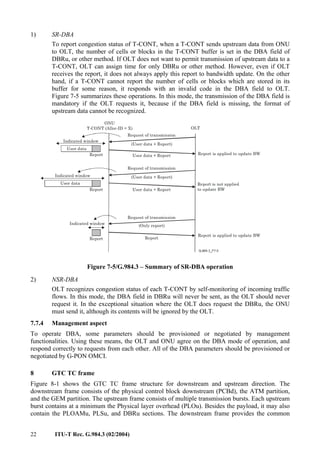
• Describe flexible access networks using optical fibre technology. The focus is primarily on
a network to support services including POTS, data, video, leased line and distributive
services.
• Describe characteristics of a Passive Optical Network (PON) with the capability of
transporting various services between the user-network interface and the service node
interface.
• Concentrate on the fibre issues. The copper issues of hybrid systems are described
elsewhere, e.g., xDSL standardization.
• Cover Transmission Convergence (TC) issues between the service node interface and the
user-network interface.
• Deal with specifications for frame format, media access control method, ranging method,
OAM functionality and security in G-PON networks.
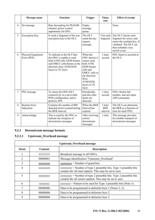
2 References
The following ITU-T Recommendations and other references contain provisions which, through
reference in this text, constitute provisions of this Recommendation. At the time of publication, the
editions indicated were valid. All Recommendations and other references are subject to revision;
users of this Recommendation are therefore encouraged to investigate the possibility of applying the
most recent edition of the Recommendations and other references listed below. A list of the
currently valid ITU-T Recommendations is regularly published. The reference to a document within
this Recommendation does not give it, as a stand-alone document, the status of a Recommendation.
[1] IEEE Standard 802.3-2002, Information technology – Telecommunication and Information
Exchange Between Systems – LAN/MAN – Specific Requirements – Part 3: Carrier Sense
Multiple Access with Collision Detection (CSMA/CD) Access Method and Physical Layer
Specifications.
[2] ITU-T Recommendation G.983.1 (1998), Broadband optical access systems based on
Passive Optical Networks (PON).
[3] ITU-T Recommendation G.983.4 (2001), A broadband optical access system with
increased service capability using dynamic bandwidth assignment (DBA).
[4] ITU-T Recommendation G.983.5 (2002), A broadband optical access system with
enhanced survivability.
[5] ITU-T Recommendation I.432.1 (1999), B-ISDN user-network interface – Physical layer
specification: General characteristics.
[6] ITU-T Recommendation I.361 (1999), B-ISDN ATM layer specification.
[7] ITU-T Recommendation G.803 (2000), Architecture of transport networks based on the
synchronous digital hierarchy (SDH).
[8] ITU-T Recommendation G.704 (1998), Synchronous frame structures used at 1544, 6312,
2048, 8448 and 44 736 kbit/s hierarchical levels.](https://image.slidesharecdn.com/t-rec-g-220521154842-a932024c/85/T-REC-G-984-3-200402-S-PDF-E-pdf-7-320.jpg)
![2 ITU-T Rec. G.984.3 (02/2004)
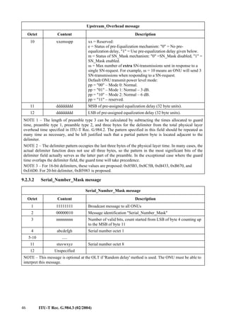
[9] ITU-T Recommendation G.707/Y.1322 (2003), Network node interface for the
synchronous digital hierarchy (SDH).
[10] ITU-T Recommendation G.984.1 (2003), Gigabit-capable Passive Optical Networks
(G-PON): General characteristics.
[11] ITU-T Recommendation G.984.2 (2003), Gigabit-capable Passive Optical Networks
(G-PON): Physical Media Dependent (PMD) layer specification.
[12] Federal Information Processing Standard 197, Advanced Encryption Standard, National
Institute of Standards and Technology, U.S. Department of Commerce, November 26, 2001.
3 Definitions
This Recommendation defines the following terms:
3.1 Broadband Passive Optical Network (B-PON): B-PONs are one-to-many broadband
optical transmission systems. B-PONs can transparently transport any type of data, for example
voice, video, IP data, etc. The B-PON is able to carry data regardless of the type of data link frame
(i.e., not only native ATM but also HDLC, Ethernet frame, etc.).
3.2 C/M-plane: C/M-Plane handles control and management information for G-PON system.
Data on OMCI is transferred through this plane.
3.3 Dynamic Bandwidth Assignment (DBA): DBA is the process by which ONUs (and their
associated T-CONTs) dynamically request upstream bandwidth (either implicitly or explicitly) and
the method, through idle cell monitoring at OLT or buffer status reporting from ONUs to OLT, the
OLT reassigns the ONUs' upstream bandwidth accordingly.
3.4 embedded OAM: Embedded OAM provides time sensitive OAM functionalities consisting
of Granting, Key switching for security, and DBA related functionalities.
3.5 Generic Framing Procedure (GFP): GFP is a framing and encapsulated method which
can be applied for any data types. It has been standardized by ITU-T.
3.6 G-PON Encapsulation Mode (GEM): GEM is a method which encapsulates data over
G-PON. Although any type of data can be encapsulated, actual types depend on service situation.
GEM provides connection-oriented communication as well as ATM. Concept and framing format
are similar to GFP (Generic Framing Procedure).
3.7 Gigabit passive Optical Network (G-PON): G-PONs are one-to-many broadband optical
transmission systems. G-PONs can transport any type of data by using ATM or GEM (G-PON
Encapsulated Mode) functionalities.
3.8 GTC framing sub-layer: It is a part of G-PON TC layer. It has responsibilities for
recognition of framing and delineation of each data portion.
3.9 Non-Status Reporting DBA (NSR-DBA): NSR-DBA invokes bandwidth assignment
which does not need report from ONU. However, it provides dynamic assignment by using traffic
monitoring by OLT itself.
3.10 Optical Access Network (OAN): The set of access links sharing the same network-side
interfaces and supported by optical access transmission systems. The OAN may include a number
of ODNs connected to the same OLT.
3.11 Optical Distribution Network (ODN): An ODN provides the optical transport between
the OLT and its associated ONUs. It uses passive optical components.
3.12 Optical Line Termination (OLT): An OLT provides the network-side interface of the
OAN, and is connected to one or more ODNs.](https://image.slidesharecdn.com/t-rec-g-220521154842-a932024c/85/T-REC-G-984-3-200402-S-PDF-E-pdf-8-320.jpg)
![ITU-T Rec. G.984.3 (02/2004) 49
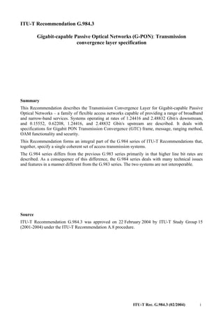
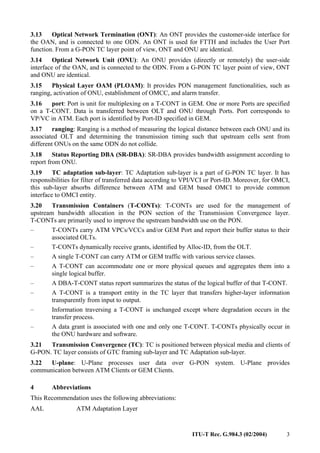
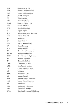
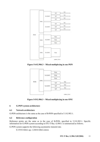
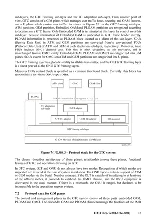
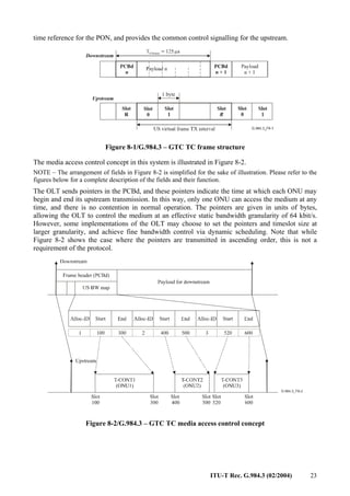
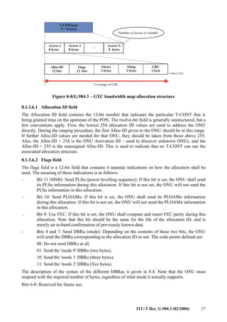
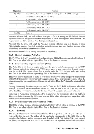
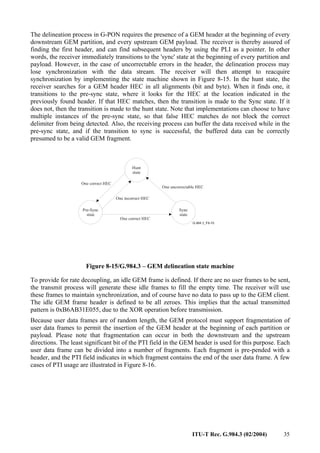
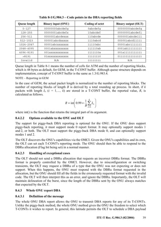
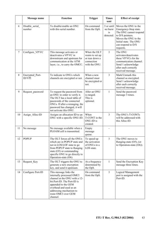
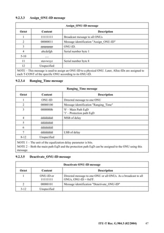
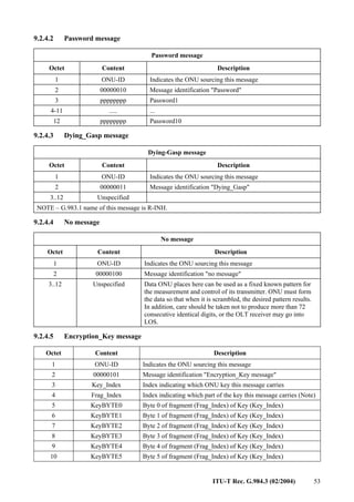
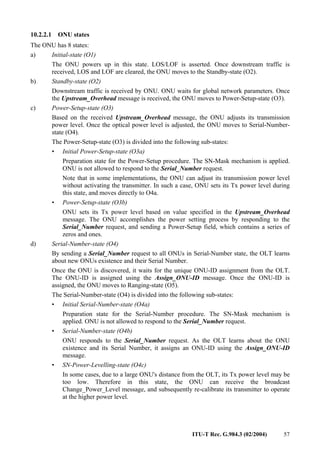
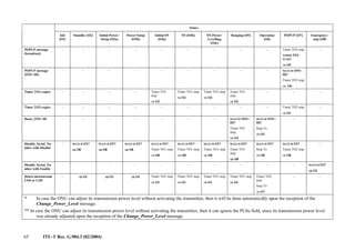
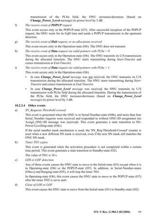
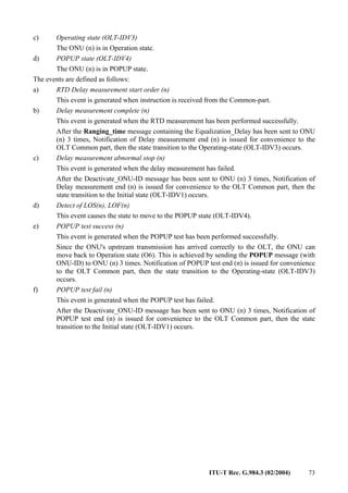
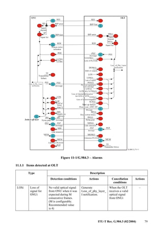
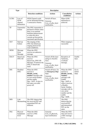
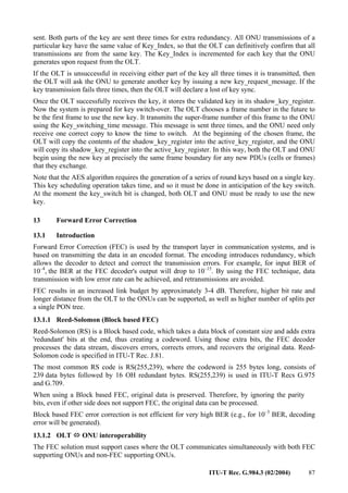
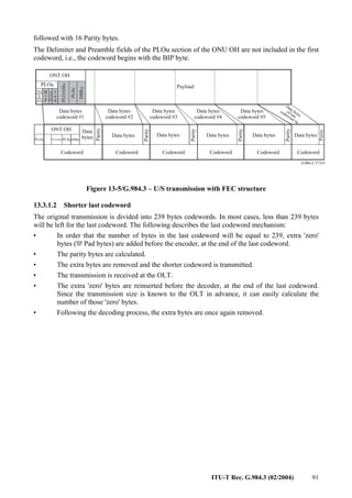
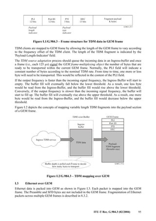
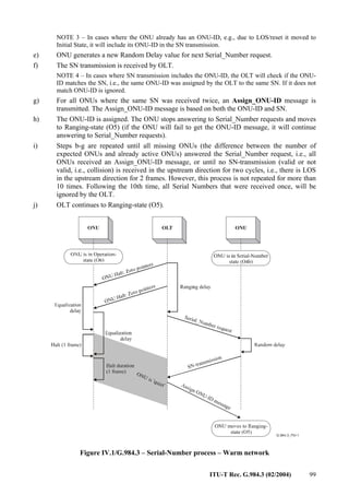
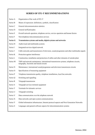
9.2.3.8 Encrypted_VPI/Port-ID message
Encrypted_VPI/Port-ID message
Octet Content Description
1 ONU-ID Directed message to one ONU
2 00001000 Message identification "Encrypted_VPI/Port-ID"
3 xxxxxxba a = 1: Encrypted
a = 0: Not Encrypted
b = 0: VPI (bytes 4, 5 are ignored)
b = 1: GEM Port-ID (bytes 6, 7 are ignored)
4 abcdefgh abcdefgh = Port-ID[11..4]
5 ijkl0000 ijklmnop = Port-ID[3..0]
6 abcdefgh abcdefgh = VPI[11..4]
7 ijkl0000 ijkl = VPI[3..0]
8-12 Unspecified
9.2.3.9 Request_Password message
Request_Password message
Octet Content Description
1 ONU-ID Directed message to one ONU
2 00001001 Message identification "Request_Password"
3-12 Unspecified
9.2.3.10 Assign_Alloc-ID message
Assign_Alloc-ID message
Octet Content Description
1 ONU-ID Directed message to one ONU
2 00001010 Message identification "Assign_Alloc-ID"
3 pppppppp Alloc-ID[11-4].
4 pppp0000 Alloc-ID[3-0].
5 Alloc-ID type Indicates for what payload type this Alloc-ID will be used:
0: ATM payload
1: GEM payload
2: DBA payload
3-255: Reserved
6-12 Unspecified](https://image.slidesharecdn.com/t-rec-g-220521154842-a932024c/85/T-REC-G-984-3-200402-S-PDF-E-pdf-55-320.jpg)
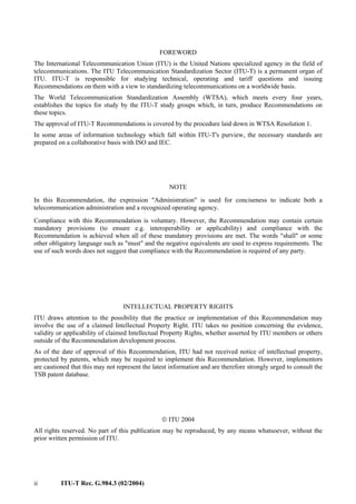
![50 ITU-T Rec. G.984.3 (02/2004)
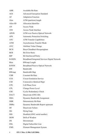
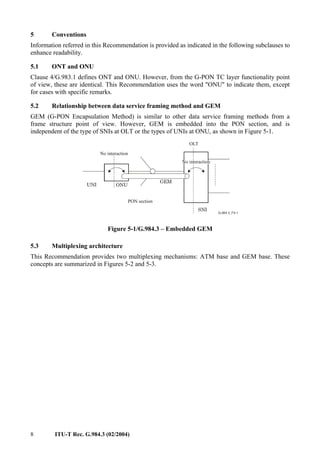
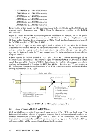
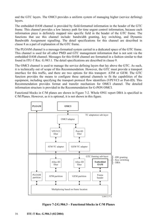
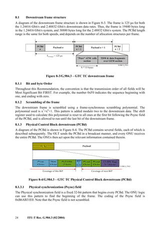
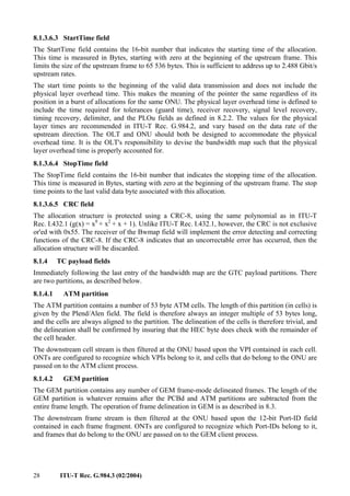
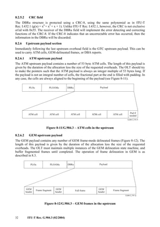
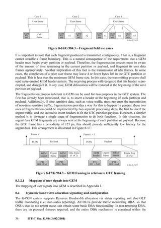
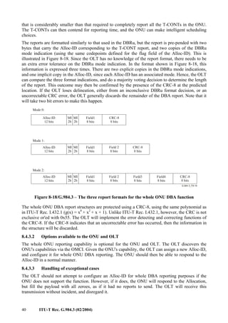
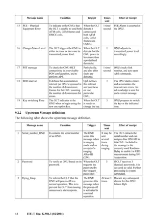
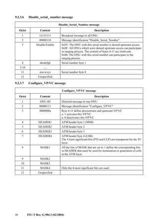
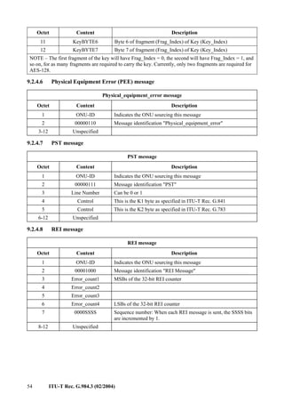
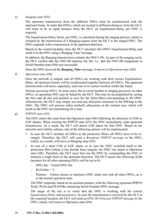
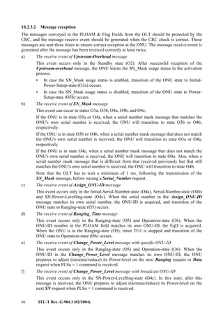
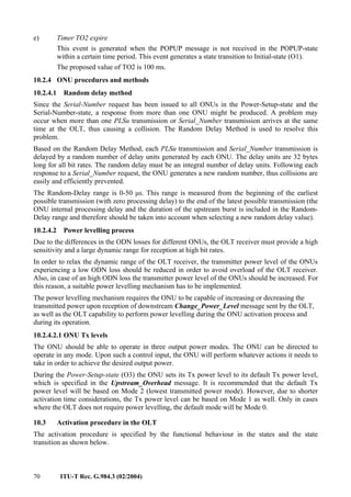
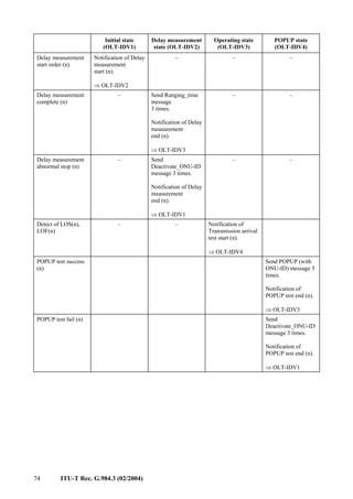
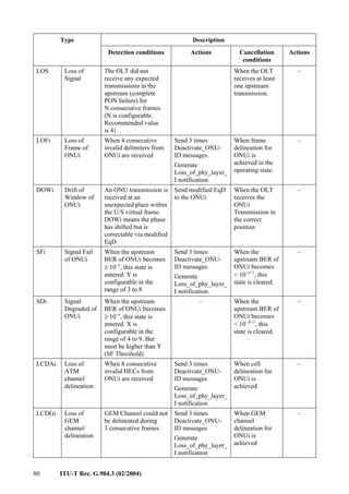
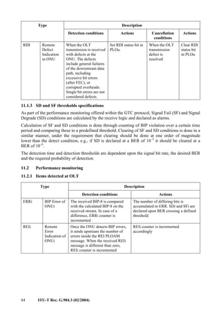
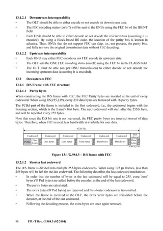
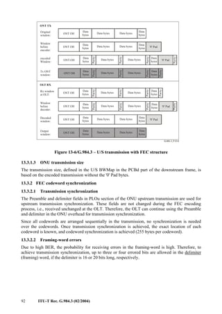
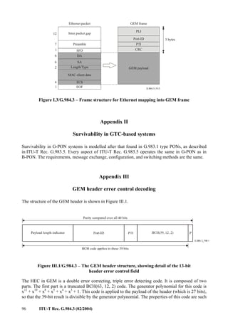
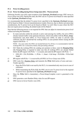
9.2.3.11 No message
No message
Octet Content Description
1 11111111 Broadcast message to all ONUs
2 00001011 Message identification "no message"
3-12 Unspecified
9.2.3.12 POPUP message
POPUP message
Octet Content Description
1 ONU-ID or
11111111
Directed message to one ONU or all ONUs. As a broadcast to all
ONUs, ONU-ID = 0xFF.
2 00001100 Message identification "POPUP"
3-12 Unspecified
NOTE – All ONUs in POPUP-state that receive a Broadcast POPUP message return to Ranging-state. An
ONU that receives a specific POPUP Message (with its ONU-ID) moves directly to Operation-state while
keeping its equalization delay, ONU-ID and Alloc-IDs.
9.2.3.13 Request_Key message
Request_Key message
Octet Content Description
1 ONU-ID Directed message to one ONU
2 00001101 Message identification "Request_Key"
3-12 Unspecified
9.2.3.14 Configure Port-ID message
Configure Port-ID message
Octet Content Description
1 ONU-ID Directed message to one ONU
2 00001110 Message identification "Configure Port-ID"
3 0000000a Byte 4-5 define downstream and upstream Port-ID
a: 1 activates this Port-ID
a: 0 deactivates this Port-ID
4 abcdefgh abcdefgh = Port-ID[11..4]
5 ijkl0000 ijklmnop = Port-ID[3..0]
6-12 Unspecified](https://image.slidesharecdn.com/t-rec-g-220521154842-a932024c/85/T-REC-G-984-3-200402-S-PDF-E-pdf-56-320.jpg)


![76 ITU-T Rec. G.984.3 (02/2004)
10.4.2 Definitions of phase relation delay
The configuration of the phase delay points described below is shown in Figure 10-2.
<ONU side>
ONU phase specification point (UP)
EqD TiO2
S
Tpd
PON
S
R
TiS2
Phase detection point
PON signal
processing
R
O/E
E/O
MUX/
DMUX
PON signal
processing
Ts TiO1 Tpd TiS1
<OLT side>
OLT phase specification point (UP)
O/E
E/O
Figure 10-2/G.984.3 – Configuration of the phase delay points
10.4.2.1 Optical fibre propagation delay (Tpd)
The Optical fibre propagation delay (Tpd) is due to the optical fibre length/distance between the
OLT and ONU.
10.4.2.2 Basic transmission delay (Ts)
The Basic transmission delay (Ts) is due to the PON signal processing in the ONU.
10.4.2.3 Optical delay
The Optical delay (TiO1, TiO2, TiS1, TiS2) is due to optoelectrical and electro-optical conversion
in the ONU and OLT.
10.4.2.4 Equalization-Delay (EqD)
The Equalization delay is an internal delay in the ONU, set and controlled by the OLT. The purpose
of this parameter is to delay the upstream transmission, so it arrives at the OLT at the correct phase.
10.4.2.5 Measured round trip delay
When measuring the round trip delay (RTD) to a specific ONU, using the ranging procedure, the
Equalization-delay is conventionally set to zero; however, this may be set to some pre-defined
value. Therefore, the result will be based on the sum of the following delays:
RTD = 2*Tpd + Ts + TiO1 + TiO2 + TiS1 + TiS2 + EqD
It is estimated that as sufficient signal processing time in the OLT and ONU, the value of
Ts + TiO1 + TiO2 + TiS1 + TiS2 should be lower than 50 µs.
In addition, 2*Tpd is equal to:
=
µs
km
0.1
[km]
ONU
to
Distance
Tpd
*
2
10.4.2.6 Equalized round trip delay
Due to the different distances of the ONUs from the OLT, it is required that the upstream phase of
all ONUs will be the same. Therefore, the ONU's Equalization delay (EqD) is set in such a way that
all ONUs will have the same constant equalized round trip delay (Teqd).](https://image.slidesharecdn.com/t-rec-g-220521154842-a932024c/85/T-REC-G-984-3-200402-S-PDF-E-pdf-82-320.jpg)
![ITU-T Rec. G.984.3 (02/2004) 77
The equalized round trip delay (Teqd), is defined as:
Teqd = RTD(n) + EqD(n)
Accordingly, the ONU's Equalization delay (for ONU n) is calculated by:
EqD(n) = Teqd – RTD(n)
10.4.3 Phase monitoring and updating RTD
Once the ONU is supplied with its Equalization-Delay factor, it is synchronized to the beginning of
the upstream frame. The actual upstream data is transmitted in a specific ONU transmission (a
group of Time Slots) inside the upstream frame according to the received downstream pointers.
The beginning of the upstream frame will be delayed in reference to the beginning of the received
downstream frame by the Equalization-Delay factor.
Downstream data
Upstream data
Equalization delay
Downstrean
frame pulse
Upstream
frame pulse
ONU window start
ONU upstream
window
ONU window width
Downstream header
Figure 10-3/G.984.3 – Upstream frame synchronization
The ONU's upstream transmission is expected to arrive in a fixed time during the upstream frame.
The arrival phase of the ONU transmission may drift due to aging and temperature changes, etc. In
those cases, the Equalization-Delay can be recalculated/updated from the drift of the upstream
transmission. This way no additional Ranging process is required.
The change in the Equalization-Delay will be equal to the drift time with opposite sign. Therefore,
if the frame is early, the drift time will be added to the Equalization-Delay. If the frame is late, the
drift time will be subtracted from the Equalization-Delay.
The new Equalization-Delay value will be calculated by the OLT and will be updated at the ONU,
using the Ranging_Time PLOAM message.
10.4.4 RTD measurement process
Round-Trip-Delay [RTD] is the time from first bit/byte of the Ranging-request in the downstream
frame till the reception of the Ranging-transmission's last bit/byte. It is used for the calculation of
the Equalization-Delay.
10.4.4.1 Criteria for successful or failed RTD measurement
Some inaccuracies might occur during the ranging procedure. In order to reduce these inaccuracies,
several RTD measurements are performed before calculating the Equalization-delay factor.
A RTD measurement is considered successful if all of the following conditions are satisfied. If one
of the conditions is not satisfied, the RTD measurement is considered failed.](https://image.slidesharecdn.com/t-rec-g-220521154842-a932024c/85/T-REC-G-984-3-200402-S-PDF-E-pdf-83-320.jpg)


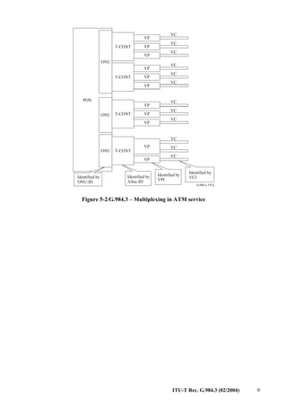
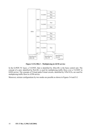
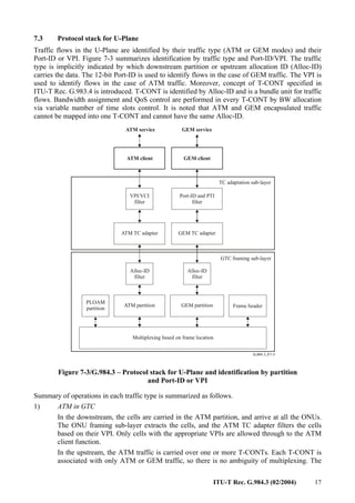
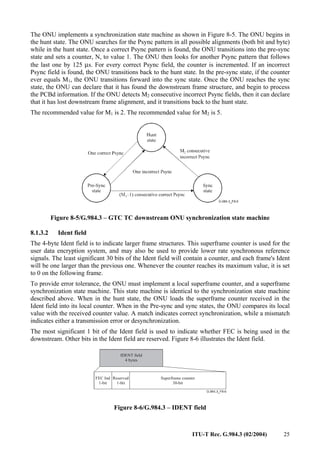
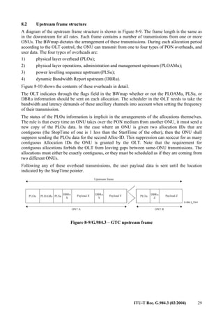
This document describes the transmission convergence layer specification for Gigabit-capable Passive Optical Networks (G-PON). It defines the frame structure, encapsulation, dynamic bandwidth allocation, operations, administration and maintenance (OAM) functionality, security, and other aspects of the transmission convergence layer. The transmission convergence layer provides the interface between the optical distribution network and the payload data and is responsible for the transmission of different traffic types over the G-PON infrastructure. It allows the transport of services such as voice, video and data at rates up to 2.5 Gbps downstream and 1.25 Gbps upstream through encapsulation using the G-PON Encapsulation Method (GEM).


