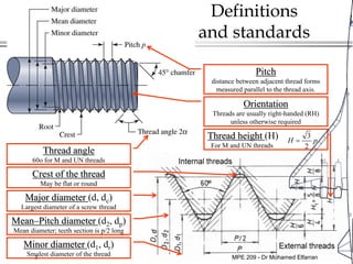
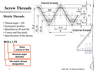
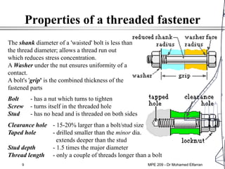
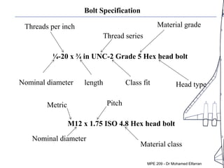
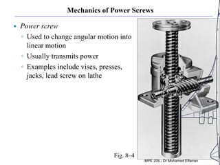
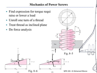
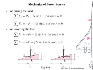
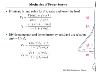
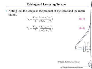
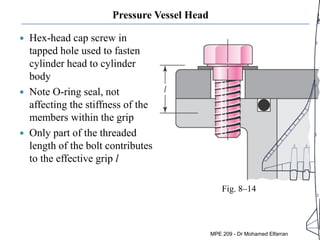
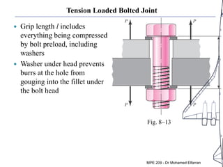
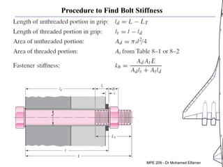
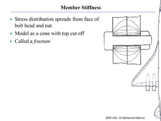
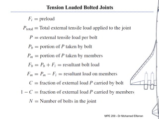
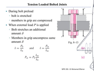
MPE 209 - Dr Mohamed Elfarran
2
Introduction
The helical-thread screw was very
important invention for application in:
• power transmission,
• angular to linear motion change,
• generation of large forces,
• non-permanent joints.
Fastening: the major target is to reduce
number of joins. One of the most
interesting subjects in engineering:
Example:
- Boeing 747 requires as many as 2.5 million fasteners. Some are very expensive.
Designer’s aim is to select an adequate fastener (bolt, nut, cap, screw …) for an
application in question: - the shape and the arrangement
- the size and other functional parameters
- to check if selected fastener can sustain required load
MPE 209 - Dr Mohamed Elfarran
Ahmed Kovacevic, City University London
3
Definitions
and standards
Pitch
distance between adjacent thread forms
measured parallel to the thread axis.
Major diameter (d, dc)
Largest diameter of a screw thread
Mean–Pitch diameter (d2, dp)
Mean diameter; teeth section is p/2 long
Minor diameter (d1, dr)
Smalest diameter of the thread
Orientation
Threads are usually right-handed (RH)
unless otherwise required
Thread angle
60o for M and UN threads
Thread height (H)
For M and UN threads
3
2
H p
=
Crest of the thread
May be flat or round
MPE 209 - Dr Mohamed Elfarran
Design web
4
Screw Threads
Metric Threads:
• Thread angle = 60o
• Symmetric profiles
• Identified as M and MJ
• Coarse and fine pitch
• Specification of the thread:
M12 x 1.75
The metric thread
designation
Nominal major
diameter
Pitch:
coarse or fine
MPE 209 - Dr Mohamed Elfarran
Ahmed Kovacevic, City University London
5
(all dimensions in mm)
Metric
threads
MPE 209 - Dr Mohamed Elfarran
Design web
6
Screw Threads
Metric Threads:
• Thread angle = 60o
• Symmetric profiles
• Identified as M and MJ
• Coarse and fine pitch
• Specification of the thread:
M12 x 1.75
The metric thread
designation
Unified threads:
(usually pipe threads)
Thread angle = 60o
• Symmetric profiles
• Serief UN and UNR
• Coarse (C) and fine (F) pitch
• Specification of the thread:
¼ in-20 UNRC
Nominal major
diameter
Pitch:
coarse or fine
Nominal major
diameter
Threads per inch
(coarse or fine)
Thread series:
UNC, UNF,
UNRC, UNRF
MPE 209 - Dr Mohamed Elfarran
Ahmed Kovacevic, City University London
7
Unified Screw Threads (dimensions in “)
MPE 209 - Dr Mohamed Elfarran
8
Threaded Fasteners
Hexagon head bolt
Fillet – stress concentration
Start of the thread
Thread root fillet in the
plane of the nut
Ideal bolt
length:
1-2
threads
to remain
when
fully
bolted
The purpose of a bolt is to clamp two or more parts together.
The clamping load stretches or elongates the bolt and remains as preload
When tightening, bolt head should be held stationary – nut should turn.
MPE 209 - Dr Mohamed Elfarran
9
Properties of a threaded fastener
Bolt - has a nut which turns to tighten
Screw - turns itself in the threaded hole
Stud - has no head and is threaded on both sides
Clearance hole - 15-20% larger than a bolt/stud size
Taped hole - drilled smaller than the minor dia.
extends deeper than the stud
Stud depth - 1.5 times the major diameter
Thread length - only a couple of threads longer than a bolt
The shank diameter of a 'waisted' bolt is less than
the thread diameter; allows a thread run out
which reduces stress concentration.
A Washer under the nut ensures uniformity of a
contact.
A bolt's 'grip' is the combined thickness of the
fastened parts
MPE 209 - Dr Mohamed Elfarran
10
Load that a bolt can sustain
b
t
F
A
σ =
r
P
A
τ =
class no. 4.6 5.8 8.8 9.8 10.9 12.9
St Tensile [Mpa] 400 500 800 900 1000 1200
Sy Yield [Mpa] 240 400 640 720 900 1080
Sp Proof [Mpa] 225 380 590 650 830 970
Elongation % 22 20 12 10 9 8
Shear stress:
Tensile stress:
Strength
table
MPE 209 - Dr Mohamed Elfarran
11
Typical cap-screw heads
Fillister head Flat head Hexagonal socket head
MPE 209 - Dr Mohamed Elfarran
Ahmed Kovacevic, City University London
12
Other types of screw heads in use
Hexagonal washer faced regular
nut
regular nut chamfered on both sides
jam nut with washer face
jam nut chamfered on both sides
Nuts
MPE 209 - Dr Mohamed Elfarran
13
Setscrews
regular nut chamfered on both sides
jam nut with washer face
jam nut chamfered on both sides
MPE 209 - Dr Mohamed Elfarran
Bolt Specification
Nominal diameter
¼-20 x ¾ in UNC-2 Grade 5 Hex head bolt
Threads per inch
length
Thread series
Class fit
Material grade
Head type
M12 x 1.75 ISO 4.8 Hex head bolt
Metric
Nominal diameter
Pitch
Material class
MPE 209 - Dr Mohamed Elfarran
15
Multiple threaded screws
(a) Single, (b) double, (c) triple threaded screws.
l=3p
l=2p
l=p
MPE 209 - Dr Mohamed Elfarran
Design web
14
Threads for power screws
Square and Acme threads:
• Used for power transmission
• These have preferred sizes but also can vary
• Modifications to these threads are easy
Preferred Pitches for power threads:
MPE 209 - Dr Mohamed Elfarran
Mechanics of Power Screws
 Power screw
◦ Used to change angular motion into
linear motion
◦ Usually transmits power
◦ Examples include vises, presses,
jacks, lead screw on lathe
Fig. 8–4
MPE 209 - Dr Mohamed Elfarran
Mechanics of Power Screws
 Find expression for torque required to
raise or lower a load
 Unroll one turn of a thread
 Treat thread as inclined plane
 Do force analysis
Fig. 8–5
Fig. 8–6 MPE 209 - Dr Mohamed Elfarran
Mechanics of Power Screws
 For raising the load
 For lowering the load
Fig. 8–6 MPE 209 - Dr Mohamed Elfarran
Mechanics of Power Screws
 Eliminate N and solve for P to raise and lower the load
 Divide numerator and denominator by cosl and use relation
tanl = l /p dm
MPE 209 - Dr Mohamed Elfarran
Raising and Lowering Torque
 Noting that the torque is the product of the force and the mean
radius,
MPE 209 - Dr Mohamed Elfarran
Tension Loaded Bolted Joint
 Grip length l includes
everything being compressed
by bolt preload, including
washers
 Washer under head prevents
burrs at the hole from
gouging into the fillet under
the bolt head
Fig. 8–13
MPE 209 - Dr Mohamed Elfarran
Pressure Vessel Head
 Hex-head cap screw in
tapped hole used to fasten
cylinder head to cylinder
body
 Note O-ring seal, not
affecting the stiffness of the
members within the grip
 Only part of the threaded
length of the bolt contributes
to the effective grip l
Fig. 8–14
MPE 209 - Dr Mohamed Elfarran
Effective Grip Length for Tapped Holes
 For screw in tapped hole,
effective grip length is
MPE 209 - Dr Mohamed Elfarran
Bolted Joint Stiffnesses
 During bolt preload
◦ bolt is stretched
◦ members in grip are
compressed
 When external load P is
applied
◦ Bolt stretches further
◦ Members in grip
uncompress some
 Joint can be modeled as a
soft bolt spring in parallel
with a stiff member spring
Fig. 8–13
MPE 209 - Dr Mohamed Elfarran
Bolt Stiffness
 Axially loaded rod,
partly threaded and
partly unthreaded
 Consider each portion as
a spring
 Combine as two springs
in series
MPE 209 - Dr Mohamed Elfarran
Procedure to Find Bolt Stiffness
MPE 209 - Dr Mohamed Elfarran
Procedure to Find Bolt Stiffness
MPE 209 - Dr Mohamed Elfarran
Procedure to Find Bolt Stiffness
MPE 209 - Dr Mohamed Elfarran
Member Stiffness
 Stress distribution spreads from face of
bolt head and nut
 Model as a cone with top cut off
 Called a frustum
MPE 209 - Dr Mohamed Elfarran
Tension Loaded Bolted Joints
MPE 209 - Dr Mohamed Elfarran
Tension Loaded Bolted Joints
 During bolt preload
◦ bolt is stretched
◦ members in grip are compressed
 When external load P is applied
◦ Bolt stretches an additional
amount d
◦ Members in grip uncompress same
amount d Fig. 8–13
MPE 209 - Dr Mohamed Elfarran
Stiffness Constant
 Since P = Pb + Pm,
 C is defined as the stiffness constant of the joint
 C indicates the proportion of external load P that the bolt will
carry. A good design target is around 0.2.
MPE 209 - Dr Mohamed Elfarran
Bolt and Member Loads
 The resultant bolt load is
 The resultant load on the members is
 These results are only valid if the load on the members remains
negative, indicating the members stay in compression.
MPE 209 - Dr Mohamed Elfarran
17
Example
The cover of a pressurised cylinder is attached by a
self-energising seal and 6 identical bolts M10x1.5 of
class 8.8. The fluid pressure is essentially constant at 6
MPa. A safety factor of three is required. Check if the
given bolt can sustain the pressure!
P=6MPa 6 class 8.8 M10x1.5
ds=120 mm Nd=3
-----------------------------------------------------------------------------
St /σ=?
SOLUTION:
Force on the cover
caused by the pressure:
2 2
6 0.12
6 10 67858 67.9
4 4
s
c s c
d
F p A p F N kN
π π ⋅
= ⋅ = = ⋅ = =
Force on the individual bolt 67.9 11.3
6 6
c
b b
F
F F kN
= = =
From tables: Tensile stress area Proof strength
2
58
t
A mm
= 590
p
S MPa
=
Stress on each bolt: 11300 194
58
b
t
F
MPa
A
σ σ
= = =
Selected number of bolts can sustain the load
590
3.04
194
p
d
S
N
σ
= = ≈
MPE 209 - Dr Mohamed Elfarran

Mpe 209 lec 10 screw fastners

  • 1.
    MPE 209 -Dr Mohamed Elfarran
  • 2.
    2 Introduction The helical-thread screwwas very important invention for application in: • power transmission, • angular to linear motion change, • generation of large forces, • non-permanent joints. Fastening: the major target is to reduce number of joins. One of the most interesting subjects in engineering: Example: - Boeing 747 requires as many as 2.5 million fasteners. Some are very expensive. Designer’s aim is to select an adequate fastener (bolt, nut, cap, screw …) for an application in question: - the shape and the arrangement - the size and other functional parameters - to check if selected fastener can sustain required load MPE 209 - Dr Mohamed Elfarran
  • 3.
    Ahmed Kovacevic, CityUniversity London 3 Definitions and standards Pitch distance between adjacent thread forms measured parallel to the thread axis. Major diameter (d, dc) Largest diameter of a screw thread Mean–Pitch diameter (d2, dp) Mean diameter; teeth section is p/2 long Minor diameter (d1, dr) Smalest diameter of the thread Orientation Threads are usually right-handed (RH) unless otherwise required Thread angle 60o for M and UN threads Thread height (H) For M and UN threads 3 2 H p = Crest of the thread May be flat or round MPE 209 - Dr Mohamed Elfarran
  • 4.
    Design web 4 Screw Threads MetricThreads: • Thread angle = 60o • Symmetric profiles • Identified as M and MJ • Coarse and fine pitch • Specification of the thread: M12 x 1.75 The metric thread designation Nominal major diameter Pitch: coarse or fine MPE 209 - Dr Mohamed Elfarran
  • 5.
    Ahmed Kovacevic, CityUniversity London 5 (all dimensions in mm) Metric threads MPE 209 - Dr Mohamed Elfarran
  • 6.
    Design web 6 Screw Threads MetricThreads: • Thread angle = 60o • Symmetric profiles • Identified as M and MJ • Coarse and fine pitch • Specification of the thread: M12 x 1.75 The metric thread designation Unified threads: (usually pipe threads) Thread angle = 60o • Symmetric profiles • Serief UN and UNR • Coarse (C) and fine (F) pitch • Specification of the thread: ¼ in-20 UNRC Nominal major diameter Pitch: coarse or fine Nominal major diameter Threads per inch (coarse or fine) Thread series: UNC, UNF, UNRC, UNRF MPE 209 - Dr Mohamed Elfarran
  • 7.
    Ahmed Kovacevic, CityUniversity London 7 Unified Screw Threads (dimensions in “) MPE 209 - Dr Mohamed Elfarran
  • 8.
    8 Threaded Fasteners Hexagon headbolt Fillet – stress concentration Start of the thread Thread root fillet in the plane of the nut Ideal bolt length: 1-2 threads to remain when fully bolted The purpose of a bolt is to clamp two or more parts together. The clamping load stretches or elongates the bolt and remains as preload When tightening, bolt head should be held stationary – nut should turn. MPE 209 - Dr Mohamed Elfarran
  • 9.
    9 Properties of athreaded fastener Bolt - has a nut which turns to tighten Screw - turns itself in the threaded hole Stud - has no head and is threaded on both sides Clearance hole - 15-20% larger than a bolt/stud size Taped hole - drilled smaller than the minor dia. extends deeper than the stud Stud depth - 1.5 times the major diameter Thread length - only a couple of threads longer than a bolt The shank diameter of a 'waisted' bolt is less than the thread diameter; allows a thread run out which reduces stress concentration. A Washer under the nut ensures uniformity of a contact. A bolt's 'grip' is the combined thickness of the fastened parts MPE 209 - Dr Mohamed Elfarran
  • 10.
    10 Load that abolt can sustain b t F A σ = r P A τ = class no. 4.6 5.8 8.8 9.8 10.9 12.9 St Tensile [Mpa] 400 500 800 900 1000 1200 Sy Yield [Mpa] 240 400 640 720 900 1080 Sp Proof [Mpa] 225 380 590 650 830 970 Elongation % 22 20 12 10 9 8 Shear stress: Tensile stress: Strength table MPE 209 - Dr Mohamed Elfarran
  • 11.
    11 Typical cap-screw heads Fillisterhead Flat head Hexagonal socket head MPE 209 - Dr Mohamed Elfarran
  • 12.
    Ahmed Kovacevic, CityUniversity London 12 Other types of screw heads in use Hexagonal washer faced regular nut regular nut chamfered on both sides jam nut with washer face jam nut chamfered on both sides Nuts MPE 209 - Dr Mohamed Elfarran MPE 209 - Dr Mohamed Elfarran
  • 13.
    13 Setscrews regular nut chamferedon both sides jam nut with washer face jam nut chamfered on both sides MPE 209 - Dr Mohamed Elfarran
  • 14.
    Bolt Specification Nominal diameter ¼-20x ¾ in UNC-2 Grade 5 Hex head bolt Threads per inch length Thread series Class fit Material grade Head type M12 x 1.75 ISO 4.8 Hex head bolt Metric Nominal diameter Pitch Material class MPE 209 - Dr Mohamed Elfarran
  • 15.
    15 Multiple threaded screws (a)Single, (b) double, (c) triple threaded screws. l=3p l=2p l=p MPE 209 - Dr Mohamed Elfarran
  • 16.
    Design web 14 Threads forpower screws Square and Acme threads: • Used for power transmission • These have preferred sizes but also can vary • Modifications to these threads are easy Preferred Pitches for power threads: MPE 209 - Dr Mohamed Elfarran
  • 17.
    Mechanics of PowerScrews  Power screw ◦ Used to change angular motion into linear motion ◦ Usually transmits power ◦ Examples include vises, presses, jacks, lead screw on lathe Fig. 8–4 MPE 209 - Dr Mohamed Elfarran
  • 18.
    Mechanics of PowerScrews  Find expression for torque required to raise or lower a load  Unroll one turn of a thread  Treat thread as inclined plane  Do force analysis Fig. 8–5 Fig. 8–6 MPE 209 - Dr Mohamed Elfarran
  • 19.
    Mechanics of PowerScrews  For raising the load  For lowering the load Fig. 8–6 MPE 209 - Dr Mohamed Elfarran
  • 20.
    Mechanics of PowerScrews  Eliminate N and solve for P to raise and lower the load  Divide numerator and denominator by cosl and use relation tanl = l /p dm MPE 209 - Dr Mohamed Elfarran
  • 21.
    Raising and LoweringTorque  Noting that the torque is the product of the force and the mean radius, MPE 209 - Dr Mohamed Elfarran MPE 209 - Dr Mohamed Elfarran
  • 22.
    Tension Loaded BoltedJoint  Grip length l includes everything being compressed by bolt preload, including washers  Washer under head prevents burrs at the hole from gouging into the fillet under the bolt head Fig. 8–13 MPE 209 - Dr Mohamed Elfarran
  • 23.
    Pressure Vessel Head Hex-head cap screw in tapped hole used to fasten cylinder head to cylinder body  Note O-ring seal, not affecting the stiffness of the members within the grip  Only part of the threaded length of the bolt contributes to the effective grip l Fig. 8–14 MPE 209 - Dr Mohamed Elfarran
  • 24.
    Tension Loaded BoltedJoint  Grip length l includes everything being compressed by bolt preload, including washers  Washer under head prevents burrs at the hole from gouging into the fillet under the bolt head Fig. 8–13 MPE 209 - Dr Mohamed Elfarran
  • 25.
    Pressure Vessel Head Hex-head cap screw in tapped hole used to fasten cylinder head to cylinder body  Note O-ring seal, not affecting the stiffness of the members within the grip  Only part of the threaded length of the bolt contributes to the effective grip l Fig. 8–14 MPE 209 - Dr Mohamed Elfarran
  • 26.
    Effective Grip Lengthfor Tapped Holes  For screw in tapped hole, effective grip length is MPE 209 - Dr Mohamed Elfarran
  • 27.
    Bolted Joint Stiffnesses During bolt preload ◦ bolt is stretched ◦ members in grip are compressed  When external load P is applied ◦ Bolt stretches further ◦ Members in grip uncompress some  Joint can be modeled as a soft bolt spring in parallel with a stiff member spring Fig. 8–13 MPE 209 - Dr Mohamed Elfarran
  • 28.
    Bolt Stiffness  Axiallyloaded rod, partly threaded and partly unthreaded  Consider each portion as a spring  Combine as two springs in series MPE 209 - Dr Mohamed Elfarran
  • 29.
    Procedure to FindBolt Stiffness MPE 209 - Dr Mohamed Elfarran
  • 30.
    Procedure to FindBolt Stiffness MPE 209 - Dr Mohamed Elfarran
  • 31.
    Procedure to FindBolt Stiffness MPE 209 - Dr Mohamed Elfarran
  • 32.
    Member Stiffness  Stressdistribution spreads from face of bolt head and nut  Model as a cone with top cut off  Called a frustum MPE 209 - Dr Mohamed Elfarran
  • 33.
    Tension Loaded BoltedJoints MPE 209 - Dr Mohamed Elfarran
  • 34.
    Tension Loaded BoltedJoints  During bolt preload ◦ bolt is stretched ◦ members in grip are compressed  When external load P is applied ◦ Bolt stretches an additional amount d ◦ Members in grip uncompress same amount d Fig. 8–13 MPE 209 - Dr Mohamed Elfarran
  • 35.
    Stiffness Constant  SinceP = Pb + Pm,  C is defined as the stiffness constant of the joint  C indicates the proportion of external load P that the bolt will carry. A good design target is around 0.2. MPE 209 - Dr Mohamed Elfarran
  • 36.
    Bolt and MemberLoads  The resultant bolt load is  The resultant load on the members is  These results are only valid if the load on the members remains negative, indicating the members stay in compression. MPE 209 - Dr Mohamed Elfarran
  • 37.
    17 Example The cover ofa pressurised cylinder is attached by a self-energising seal and 6 identical bolts M10x1.5 of class 8.8. The fluid pressure is essentially constant at 6 MPa. A safety factor of three is required. Check if the given bolt can sustain the pressure! P=6MPa 6 class 8.8 M10x1.5 ds=120 mm Nd=3 ----------------------------------------------------------------------------- St /σ=? SOLUTION: Force on the cover caused by the pressure: 2 2 6 0.12 6 10 67858 67.9 4 4 s c s c d F p A p F N kN π π ⋅ = ⋅ = = ⋅ = = Force on the individual bolt 67.9 11.3 6 6 c b b F F F kN = = = From tables: Tensile stress area Proof strength 2 58 t A mm = 590 p S MPa = Stress on each bolt: 11300 194 58 b t F MPa A σ σ = = = Selected number of bolts can sustain the load 590 3.04 194 p d S N σ = = ≈ MPE 209 - Dr Mohamed Elfarran