Threaded Joints
Threaded jointis defined as a separable
joint of two or more machine parts that are
held together by means of a threaded
fastening such as a bolt and a nut
2.
BASIC TYPES OFSCREW FASTENING
• There are three parts of a threaded fastening, viz., a bolt or
screw, a nut and a washer.
• A bolt is a fastener with a head and straight threaded shank
and intended to be used with a nut to clamp two or more
parts.
• The same bolt can be called screw when it is threaded into a
tapped hole in one of the parts and not into the nut.
• A bolt is held stationary, while torque is applied to the nut to
make threaded joint, whereas the torque is applied to the
screw to turn it into matching threads in one of the parts.
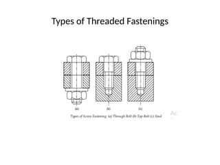
(i) Through Bolts: A through bolt is simply called a ‘bolt’ or a ‘bolt and nut.
The bolt consists of a cylindrical rod with head at one end and threads at the
other. The cylindrical portion between the head and the threads is called
shank. The shank passes through the holes in the parts to be fastened. The
threaded portion of the bolt is screwed into the nut. The head of the bolt and
the nut are either hexagonal or square. Hexagonal head bolt and nut are
popular in the machine building industry. Square head and nut are used
mostly with rough type of bolts in construction work. Through bolts are used
under the following conditions:
(a) The parts that are fastened have medium thickness, e.g., plates, flanges or
beams and space is available to accommodate the bolt head and the nut.
Space should also be available to accommodate the spanner to tighten the
nut.
(b) The parts that are fastened are made of materials, which are too weak to
make durable threads.
(c) The parts that are fastened require frequent dismantling and reassembly.
5.
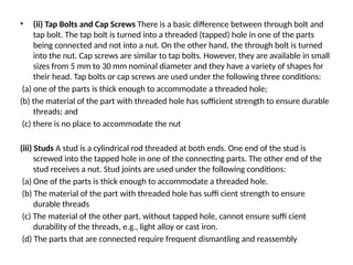
• (ii) TapBolts and Cap Screws There is a basic difference between through bolt and
tap bolt. The tap bolt is turned into a threaded (tapped) hole in one of the parts
being connected and not into a nut. On the other hand, the through bolt is turned
into the nut. Cap screws are similar to tap bolts. However, they are available in small
sizes from 5 mm to 30 mm nominal diameter and they have a variety of shapes for
their head. Tap bolts or cap screws are used under the following three conditions:
(a) one of the parts is thick enough to accommodate a threaded hole;
(b) the material of the part with threaded hole has sufficient strength to ensure durable
threads; and
(c) there is no place to accommodate the nut
(iii) Studs A stud is a cylindrical rod threaded at both ends. One end of the stud is
screwed into the tapped hole in one of the connecting parts. The other end of the
stud receives a nut. Stud joints are used under the following conditions:
(a) One of the parts is thick enough to accommodate a threaded hole.
(b) The material of the part with threaded hole has suffi cient strength to ensure
durable threads
(c) The material of the other part, without tapped hole, cannot ensure suffi cient
durability of the threads, e.g., light alloy or cast iron.
(d) The parts that are connected require frequent dismantling and reassembly
6.
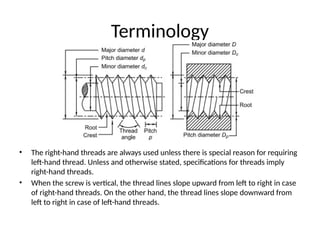
Terminology
• The right-handthreads are always used unless there is special reason for requiring
left-hand thread. Unless and otherwise stated, specifications for threads imply
right-hand threads.
• When the screw is vertical, the thread lines slope upward from left to right in case
of right-hand threads. On the other hand, the thread lines slope downward from
left to right in case of left-hand threads.
7.
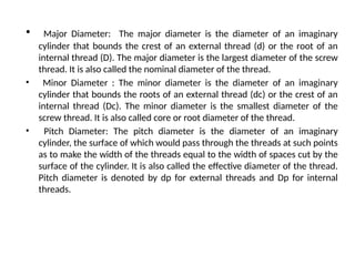
• Major Diameter:The major diameter is the diameter of an imaginary
cylinder that bounds the crest of an external thread (d) or the root of an
internal thread (D). The major diameter is the largest diameter of the screw
thread. It is also called the nominal diameter of the thread.
• Minor Diameter : The minor diameter is the diameter of an imaginary
cylinder that bounds the roots of an external thread (dc) or the crest of an
internal thread (Dc). The minor diameter is the smallest diameter of the
screw thread. It is also called core or root diameter of the thread.
• Pitch Diameter: The pitch diameter is the diameter of an imaginary
cylinder, the surface of which would pass through the threads at such points
as to make the width of the threads equal to the width of spaces cut by the
surface of the cylinder. It is also called the effective diameter of the thread.
Pitch diameter is denoted by dp for external threads and Dp for internal
threads.
8.
• Pitch :Pitch is the distance between two similar points on adjacent threads
measured parallel to the axis of the thread. It is denoted by the letter p.
• Lead : Lead is the distance that the nut moves parallel to the axis of the
screw, when the nut is given one turn.
• Thread Angle : Thread angle is the angle included between the sides of the
thread measured in an axial plane. Thread angle is 60o for ISO metric
threads.
• Tensile Stress Area : It has been observed during testing of the threaded
rods that an unthreaded rod, having a diameter equal to the mean of the
pitch diameter and the minor diameter [i.e., (dp + dc)/2] has the same
tensile strength as the threaded rod. The cross-sectional area of this
unthreaded rod is called the ‘tensile-stress area’. This area is used for the
purpose of calculating the tensile strength of the bolts.
9.
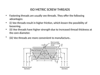
ISO METRIC SCREWTHREADS
• Fastening threads are usually vee threads. They offer the following
advantages:
• (i) Vee threads result in higher friction, which lessen the possibility of
loosening.
• (ii) Vee threads have higher strength due to increased thread thickness at
the core diameter.
• (iii) Vee threads are more convenient to manufacture.
10.
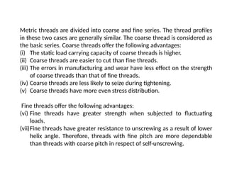
Metric threads aredivided into coarse and fine series. The thread profiles
in these two cases are generally similar. The coarse thread is considered as
the basic series. Coarse threads offer the following advantages:
(i) The static load carrying capacity of coarse threads is higher.
(ii) Coarse threads are easier to cut than fine threads.
(iii) The errors in manufacturing and wear have less effect on the strength
of coarse threads than that of fine threads.
(iv) Coarse threads are less likely to seize during tightening.
(v) Coarse threads have more even stress distribution.
Fine threads offer the following advantages:
(vi) Fine threads have greater strength when subjected to fluctuating
loads.
(vii)Fine threads have greater resistance to unscrewing as a result of lower
helix angle. Therefore, threads with fine pitch are more dependable
than threads with coarse pitch in respect of self-unscrewing.
11.
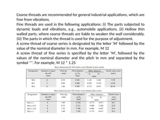
Coarse threads arerecommended for general industrial applications, which are
free from vibrations.
Fine threads are used in the following applications: (i) The parts subjected to
dynamic loads and vibrations, e.g., automobile applications. (ii) Hollow thin
walled parts, where coarse threads are liable to weaken the wall considerably.
(iii) The parts in which the thread is used for the purpose of adjustment.
A screw thread of coarse series is designated by the letter ‘M’ followed by the
value of the nominal diameter in mm. For example, M 12
A screw thread of fine series is specified by the letter ‘M’, followed by the
values of the nominal diameter and the pitch in mm and separated by the
symbol ‘*’. For example, M 12 * 1.25
12.
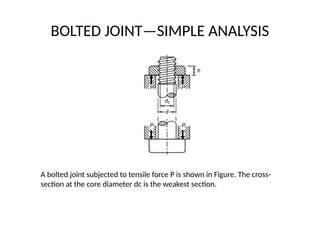
BOLTED JOINT—SIMPLE ANALYSIS
Abolted joint subjected to tensile force P is shown in Figure. The cross-
section at the core diameter dc is the weakest section.
13.
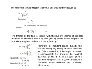
The maximum tensilestress in the bolt at this cross-section is given by,
The threads of the bolt in contact with the nut are sheared at the core
diameter dc. The shear area is equal to (p dc h), where h is the height of the
nut. The strength of the bolt in shear is given by,
Therefore, for standard coarse threads, the
threads are equally strong in failure by shear
and failure by tension, if the height of the nut
is approximately 0.4 times of the nominal
diameter of the bolt. The height of the
standard hexagonal nut is (0.8d). Hence, the
threads of the bolt in the standard nut will not
fail by shear.
14.
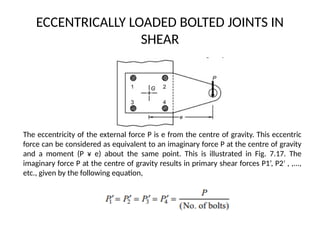
ECCENTRICALLY LOADED BOLTEDJOINTS IN
SHEAR
The eccentricity of the external force P is e from the centre of gravity. This eccentric
force can be considered as equivalent to an imaginary force P at the centre of gravity
and a moment (P ¥ e) about the same point. This is illustrated in Fig. 7.17. The
imaginary force P at the centre of gravity results in primary shear forces P1’, P2 , ,...,
′
etc., given by the following equation,
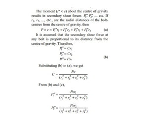
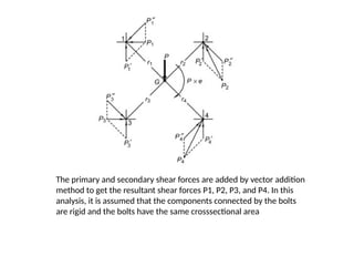
16.
The primary andsecondary shear forces are added by vector addition
method to get the resultant shear forces P1, P2, P3, and P4. In this
analysis, it is assumed that the components connected by the bolts
are rigid and the bolts have the same crosssectional area
17.
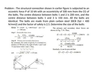
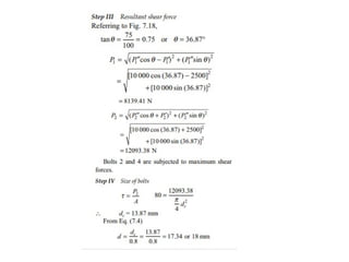
Problem : Thestructural connection shown in earlier figure is subjected to an
eccentric force P of 10 kN with an eccentricity of 500 mm from the CG of
the bolts. The centre distance between bolts 1 and 2 is 200 mm, and the
centre distance between bolts 1 and 3 is 150 mm. All the bolts are
identical. The bolts are made from plain carbon steel 30C8 (Syt = 400
N/mm2) and the factor of safety is 2.5. Determine the size of the bolts
19.
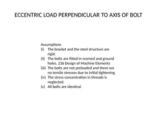
ECCENTRIC LOAD PERPENDICULARTO AXIS OF BOLT
Assumptions
(i) The bracket and the steel structure are
rigid.
(ii) The bolts are fitted in reamed and ground
holes. 236 Design of Machine Elements
(iii) The bolts are not preloaded and there are
no tensile stresses due to initial tightening.
(iv) The stress concentration in threads is
neglected.
(v) All bolts are identical
20.
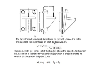
The force Presults in direct shear force on the bolts. Since the bolts
are identical, the shear force on each bolt is given by,
The moment (P ¥ e) tends to tilt the bracket about the edge C. As shown in
Fig. each bolt is stretched by an amount (d) which is proportional to its
vertical distance from the point C. Or,
21.
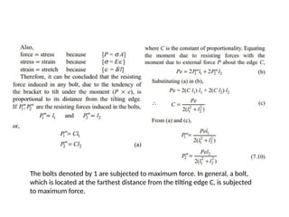
The bolts denotedby 1 are subjected to maximum force. In general, a bolt,
which is located at the farthest distance from the tilting edge C, is subjected
to maximum force.
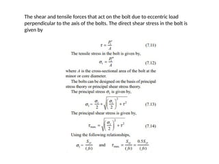
22.
The shear andtensile forces that act on the bolt due to eccentric load
perpendicular to the axis of the bolts. The direct shear stress in the bolt is
given by
23.
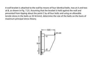
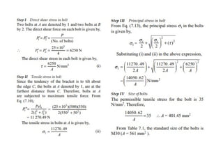
A wall bracketis attached to the wall by means of four identical bolts, two at A and two
at B, as shown in Fig. 7.21. Assuming that the bracket is held against the wall and
prevented from tipping about the point C by all four bolts and using an allowable
tensile stress in the bolts as 35 N/mm2, determine the size of the bolts on the basis of
maximum principal stress theory.
25.
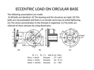
ECCENTRIC LOAD ONCIRCULAR BASE
The following assumptions are made:
(i) All bolts are identical. (ii) The bearing and the structure are rigid. (iii) The
bolts are not preloaded and there is no tensile stress due to initial tightening.
(iv) The stress concentration in the threads is neglected. (v) The bolts are
relieved of shear stresses by using dowel pins.
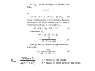
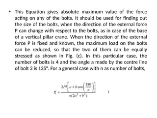
27.
• This Equationgives absolute maximum value of the force
acting on any of the bolts. It should be used for finding out
the size of the bolts, when the direction of the external force
P can change with respect to the bolts, as in case of the base
of a vertical pillar crane. When the direction of the external
force P is fixed and known, the maximum load on the bolts
can be reduced, so that the two of them can be equally
stressed as shown in Fig. (c). In this particular case, the
number of bolts is 4 and the angle a made by the centre line
of bolt 2 is 135°. For a general case with n as number of bolts,
28.
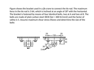
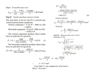
Figure shows thebracket used in a jib crane to connect the tie rod. The maximum
force in the tie rod is 5 kN, which is inclined at an angle of 30° with the horizontal.
The bracket is fastened by means of four identical bolts, two at A and two at B. The
bolts are made of plain carbon steel 30C8 (Syt = 400 N/mm2) and the factor of
safety is 5. Assume maximum shear stress theory and determine the size of the
bolts

![• Pitch : Pitch is the distance between two similar points on adjacent threads
measured parallel to the axis of the thread. It is denoted by the letter p.
• Lead : Lead is the distance that the nut moves parallel to the axis of the
screw, when the nut is given one turn.
• Thread Angle : Thread angle is the angle included between the sides of the
thread measured in an axial plane. Thread angle is 60o for ISO metric
threads.
• Tensile Stress Area : It has been observed during testing of the threaded
rods that an unthreaded rod, having a diameter equal to the mean of the
pitch diameter and the minor diameter [i.e., (dp + dc)/2] has the same
tensile strength as the threaded rod. The cross-sectional area of this
unthreaded rod is called the ‘tensile-stress area’. This area is used for the
purpose of calculating the tensile strength of the bolts.](https://image.slidesharecdn.com/threadedjoints1-250328060239-577f52e1/85/Threadedjointmechanicaldeignanddraw-pptx-8-320.jpg)


![ME 312 Mechanical Machine Design [Screws, Bolts, Nuts]](https://cdn.slidesharecdn.com/ss_thumbnails/me312-dsulec10-screws-170213050612-thumbnail.jpg?width=640&height=640&fit=bounds)


