SlideShare a Scribd company logo
CPU BUSES:
A computer system encompasses much more than the CPU;it also includes
memory and I/O devices. The bus is the mechanism by which the CPU
communicates with memory and devices. A bus is, at a minimum, a collection
of wires, but the bus also defines a protocol by which the CPU, memory, and
devices communicate. One of the major roles of the bus is to provide an
interface to memory. (Of course, I/O devices also connect to the bus.)
1. Bus Protocols:
The basic building block of most bus protocols is the four-cycle handshake,
illustrated in Figure 2.1. The handshake ensures that when two devices want to
communicate, one is ready to transmit and the other is ready to receive.
The handshake uses a pair of wires dedicated to the handshake: enq (meaning
enquiry) and ack (meaning acknowledge). Extra wires are used for the data
transmitted during the handshake. The four cycles are described below.
Device 1 raises its output to signal an enquiry, which tells device 2 that it should
get ready to listen for data.
When device 2 is ready to receive, it raises its output to signal an
acknowledgment. At this point, devices 1 and 2 can transmit or receive.
Once the data transfer is complete, device 2 lowers its output, signaling that it
has received the data.
After seeing that ack has been released, device 1 lowers its output.
At the end of the handshake, both handshaking signals are low, just as they were
at the start of the handshake. The system has thus returned to its original state in
readiness for another handshake-enabled data transfer.
Microprocessor buses build on the handshake for communication between the
CPU and other system components. The term bus is used in two ways.
The most basic use is as a set of related wires, such as address wires. However,
the term may also mean a protocol for communicating between components.
To avoid confusion, we will use the term bundle to refer to a set of related
signals. The fundamental bus operations are reading and writing. Figure 2.2
shows the structure of a typical bus that supports reads and writes.
The major components follow:
Clock provides synchronization to the bus components,
R/W is true when the bus is reading and false when the bus is writing,
Address is an a-bit bundle of signals that transmits the address for an access,
Data is an n-bit bundle of signals that can carry data to or from the CPU, and
Data ready signals when the values on the data bundle are valid.
2. DMA:
Standard bus transactions require the CPU to be in the middle of
every read and write transaction. However, there are certain types of data
transfers in which the CPU does not need to be involved.
For example, a high-speed I/O device may want to transfer a block of data into
memory. While it is possible to write a program that alternately reads the device
and writes to memory, it would be faster to eliminate the CPU’s involvement
and let the device and memory communicate directly. This capability requires
that some unit other than the CPU be able to control operations on the bus.
Direct memory access (DMA) is a bus operation that allows reads and writes
not controlled by the CPU. A DMA transfer is controlled by a DMA controller,
which requests control of the bus from the CPU.
After gaining control, the DMA controller performs read and write operations
directly between devices and memory. Figure 2.3 shows the configuration of a
bus with a DMA controller. The DMA requires the CPU to provide two
additional bus signals:
The bus request is an input to the CPU through which DMA controllers ask for
ownership of the bus.
The bus grant signals that the bus has been granted to the DMA controller.
A device that can initiate its own bus transfer is known as a bus master. Devices
that do not have the capability to be bus masters do not need to connect to a bus
request and bus grant.
The DMA controller uses these two signals to gain control of the bus using a
classic four-cycle handshake. The bus request is asserted by the DMA controller
when it wants to control the bus, and the bus grant is asserted by the CPU when
the bus is ready.
The CPU will finish all pending bus transactions before granting control of the
bus to the DMA controller. When it does grant control, it stops driving the other
bus signals: R/W, address, and so on. Upon becoming bus master, the DMA
controller has control of all bus signals (except, of course, for bus request and
bus grant).
COMPONENT INTERFACING:
Building the logic to interface a device to a bus is not too difficult but does take
some attention to detail. We first consider interfacing memory components to
the bus, since that is relatively simple, and then use those concepts to interface
to other types of devices.
1. Memory Interfacing
If we can buy a memory of the exact size we need, then the memory structure is
simple. If we need more memory than we can buy in a single chip, then we must
construct the memory out of several chips. We may also want to build a
memory that is wider than we can buy on a single chip; for example, we cannot
generally buy a 32-bit-wide memory chip. We can easily construct a memory of
a given width (32 bits, 64 bits, etc.) by placing RAMs in parallel.
We also need logic to turn the bus signals into the appropriate memory signals.
For example, most busses won’t send address signals in row and column form.
We also need to generate the appropriate refresh signals.
2. Device Interfacing
Some I/O devices are designed to interface directly to a particular bus,
forming glueless interfaces. But glue logic is required when a device is
connected to a bus for which it is not designed.
An I/O device typically requires a much smaller range of addresses than a
memory, so addresses must be decoded much more finely. Some additional
logic is required to cause the bus to read and write the device’s registers.
DESIGN WITH MICROPROCESSORS:
System Architecture
We know that an architecture is a set of elements and the relationships between
them that together form a single unit. The architecture of an embedded
computing system is the blueprint for implementing that system—it tells you
what components you need and how you put them together.
The architecture of an embedded computing system includes both hardware and
software elements.
Let’s consider each in turn.
The hardware architecture of an embedded computing system is the more
obvious manifestation of the architecture since you can touch it and feel it. It
includes several elements, some of which may be less obvious than others.
CPU An embedded computing system clearly contains a microprocessor. But
which one? There are many different architectures, and even within an
architecture we can select between models that vary in clock speed, bus data
width, integrated peripherals, and so on. The choice of the CPU is one of the
most important, but it cannot be made without considering the software that will
execute on the machine.
Bus The choice of a bus is closely tied to that of a CPU, since the bus is an
integral part of the microprocessor. But in applications that make intensive use
of the bus due to I/O or other data traffic, the bus may be more of a limiting
factor than the CPU. Attention must be paid to the required data bandwidths to
be sure that the bus can handle the traffic.
Memory Once again, the question is not whether the system will have memory
but the characteristics of that memory. The most obvious characteristic is total
size, which depends on both the required data volume and the size of the
program instructions. The ratio of ROM to RAM and selection of DRAM
versus SRAM can have a significant influence on the cost of the system. The
speed of the memory will play a large part in determining system performance.
Input and output devices The user’s view of the input and output mechanisms
may not correspond to the devices connected to the microprocessor. For
example, a set of switches and knobs on a front panel may all be controlled by a
single microcontroller, which is in turn connected to the main CPU.
For a given function, there may be several different devices of varying
sophistication and cost that can do the job. The difficulty of using a particular
device, such as the amount of glue logic required to interface it, may also play a
role in final device selection.
Hardware Design
The design complexity of the hardware platform can vary greatly, from a totally
off-the-shelf solution to a highly customized design.
At the board level, the first step is to consider evaluation boards supplied by the
microprocessor manufacturer or another company working in collaboration with
the manufacturer. Evaluation boards are sold for many microprocessor systems;
they typically include the CPU, some memory, a serial link for downloading
programs, and some minimal number of I/O devices.
The evaluation board may be a complete solution or provide what you need
with only slight modifications. If the evaluation board is supplied by the
microprocessor vendor, its design (netlist, board layout, etc.) may be available
from the vendor; companies provide such information to make it easy for
customers to use their microprocessors. If the evaluation board comes from a
third party, it may be possible to contract them to design a new board with your
required modifications, or you can start from scratch on a new board design.
The other major task is the choice of memory and peripheral components. In the
case of I/O devices, there are two alternatives for each device: selecting a
component from a catalog or designing one yourself. When shopping for
devices from a catalog, it is important to read data sheets carefully it may not be
trivial to figure out whether the device does what you need it to do.
DEVELOPMENT AND DEBUGGING:
Development Environments
A typical embedded computing system has a relatively small amount of
everything, including CPU horsepower, memory, I/O devices, and so forth. As a
result, it is common to do at least part of the software development on a PC or
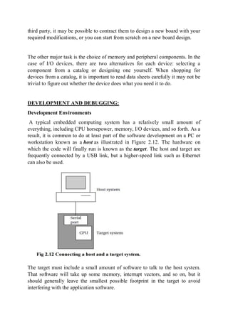
workstation known as a host as illustrated in Figure 2.12. The hardware on
which the code will finally run is known as the target. The host and target are
frequently connected by a USB link, but a higher-speed link such as Ethernet
can also be used.
The target must include a small amount of software to talk to the host system.
That software will take up some memory, interrupt vectors, and so on, but it
should generally leave the smallest possible footprint in the target to avoid
interfering with the application software.
The host should be able to do the following:
load programs into the target,
start and stop program execution on the target, and
examine memory and CPU registers.
Debugging Techniques:
A good deal of software debugging can be done by compiling and executing the
code on a PC or workstation. But at some point it inevitably becomes necessary
to run code on the embedded hardware platform.
Embedded systems are usually less friendly programming environments than
PCs. Nonetheless, the resourceful designer has several options available for
debugging the system.
The serial port found on most evaluation boards is one of the most important
debugging tools. In fact, it is often a good idea to design a serial port into an
embedded system even if it will not be used in the final product; the serial port
can be used not only for development debugging but also for diagnosing
problems in the field.
Another very important debugging tool is the breakpoint. The simplest form of
a breakpoint is for the user to specify an address at which the program’s
execution is to break. When the PC reaches that address, control is returned to
the monitor program. From the monitor program, the user can examine and/or
modify CPU registers, after which execution can be continued. Implementing
breakpoints does not require using exceptions or external devices.
Debugging Challenges
Logical errors in software can be hard to track down, but errors in real-time
code can create problems that are even harder to diagnose. Real-time programs
are required to finish their work within a certain amount of time; if they run too
long, they can create very unexpected behavior.
The exact results of missing real-time deadlines depend on the detailed
characteristics of the I/O devices and the nature of the timing violation. This
makes debugging real-time problems especially difficult.
Unfortunately, the best advice is that if a system exhibits truly unusual behavior,
missed deadlines should be suspected. In-circuit emulators, logic analyzers, and
even LEDs can be useful tools in checking the execution time of real-time code
to determine whether it in fact meets its deadline.

More Related Content

Similar to Module-3 The embedded computing platfrom and program design.pdf

Co notes
Co notesCo notes
Data conversion
Data conversionData conversion
Data conversion
Samuel Igbanogu
 
Cliff sugerman
Cliff sugermanCliff sugerman
Cliff sugerman
clifford sugerman
 
WHAT-ARE-THE-DIFFERENT-HARDWARE-COMPONENT-OF-COMPUTER.pptx
WHAT-ARE-THE-DIFFERENT-HARDWARE-COMPONENT-OF-COMPUTER.pptxWHAT-ARE-THE-DIFFERENT-HARDWARE-COMPONENT-OF-COMPUTER.pptx
WHAT-ARE-THE-DIFFERENT-HARDWARE-COMPONENT-OF-COMPUTER.pptx
ssuserfbb80b
 
Computer organization research, everything that u want (2020)
Computer organization research, everything that u want (2020)Computer organization research, everything that u want (2020)
Computer organization research, everything that u want (2020)
Ahmed Magdy
 
Csc118 chapter1
Csc118 chapter1Csc118 chapter1
Csc118 chapter1
Mazlan Salleh
 
Motherboard components and their functions
Motherboard components and their functionsMotherboard components and their functions
Motherboard components and their functions
Abdullah-Al- Mahmud
 
Computer System Architecture
Computer System ArchitectureComputer System Architecture
Computer System Architecture
Brenda Debra
 
Itc lec 3 Ip cycle , system unit, interface
Itc lec 3 Ip cycle , system unit, interfaceItc lec 3 Ip cycle , system unit, interface
Itc lec 3 Ip cycle , system unit, interface
AnzaDar3
 
Chapter 1 CSC118
Chapter 1 CSC118 Chapter 1 CSC118
Chapter 1 CSC118
Luqman al-Hakim
 
System Unit
System UnitSystem Unit
System Unit
Reina Mae Salido
 
Ch # 04 computer hardware
Ch # 04 computer hardware Ch # 04 computer hardware
Ch # 04 computer hardware
MuhammadRobeel3
 
Computer architecture
Computer architectureComputer architecture
Computer architecture
Nguyen Le Hung Nguyen
 
Csc 2313 (lecture 1)
Csc 2313 (lecture 1)Csc 2313 (lecture 1)
Csc 2313 (lecture 1)
umardanjumamaiwada
 
Csc 2313 (lecture 1)
Csc 2313 (lecture 1)Csc 2313 (lecture 1)
Csc 2313 (lecture 1)
umardanjumamaiwada
 
Design and implementation of microprocessor trainer bus system
Design and implementation of microprocessor trainer bus systemDesign and implementation of microprocessor trainer bus system
Design and implementation of microprocessor trainer bus system
IJARIIT
 
COMPUTER BASIC AND FUNDAMENTAL AND ITS ORGANISATION.pptx
COMPUTER BASIC AND FUNDAMENTAL AND ITS ORGANISATION.pptxCOMPUTER BASIC AND FUNDAMENTAL AND ITS ORGANISATION.pptx
COMPUTER BASIC AND FUNDAMENTAL AND ITS ORGANISATION.pptx
PannaBushratul
 
Chap2 comp architecture
Chap2 comp architectureChap2 comp architecture
Chap2 comp architecture
raksharao
 
Hcs Topic 2 Computer Structure V2
Hcs Topic 2  Computer Structure V2Hcs Topic 2  Computer Structure V2
Hcs Topic 2 Computer Structure V2
Naruin
 
Hcs Topic 2 Computer Structure V2
Hcs Topic 2  Computer Structure V2Hcs Topic 2  Computer Structure V2
Hcs Topic 2 Computer Structure V2
Kyle
 

Similar to Module-3 The embedded computing platfrom and program design.pdf (20)

Co notes
Co notesCo notes
Co notes
 
Data conversion
Data conversionData conversion
Data conversion
 
Cliff sugerman
Cliff sugermanCliff sugerman
Cliff sugerman
 
WHAT-ARE-THE-DIFFERENT-HARDWARE-COMPONENT-OF-COMPUTER.pptx
WHAT-ARE-THE-DIFFERENT-HARDWARE-COMPONENT-OF-COMPUTER.pptxWHAT-ARE-THE-DIFFERENT-HARDWARE-COMPONENT-OF-COMPUTER.pptx
WHAT-ARE-THE-DIFFERENT-HARDWARE-COMPONENT-OF-COMPUTER.pptx
 
Computer organization research, everything that u want (2020)
Computer organization research, everything that u want (2020)Computer organization research, everything that u want (2020)
Computer organization research, everything that u want (2020)
 
Csc118 chapter1
Csc118 chapter1Csc118 chapter1
Csc118 chapter1
 
Motherboard components and their functions
Motherboard components and their functionsMotherboard components and their functions
Motherboard components and their functions
 
Computer System Architecture
Computer System ArchitectureComputer System Architecture
Computer System Architecture
 
Itc lec 3 Ip cycle , system unit, interface
Itc lec 3 Ip cycle , system unit, interfaceItc lec 3 Ip cycle , system unit, interface
Itc lec 3 Ip cycle , system unit, interface
 
Chapter 1 CSC118
Chapter 1 CSC118 Chapter 1 CSC118
Chapter 1 CSC118
 
System Unit
System UnitSystem Unit
System Unit
 
Ch # 04 computer hardware
Ch # 04 computer hardware Ch # 04 computer hardware
Ch # 04 computer hardware
 
Computer architecture
Computer architectureComputer architecture
Computer architecture
 
Csc 2313 (lecture 1)
Csc 2313 (lecture 1)Csc 2313 (lecture 1)
Csc 2313 (lecture 1)
 
Csc 2313 (lecture 1)
Csc 2313 (lecture 1)Csc 2313 (lecture 1)
Csc 2313 (lecture 1)
 
Design and implementation of microprocessor trainer bus system
Design and implementation of microprocessor trainer bus systemDesign and implementation of microprocessor trainer bus system
Design and implementation of microprocessor trainer bus system
 
COMPUTER BASIC AND FUNDAMENTAL AND ITS ORGANISATION.pptx
COMPUTER BASIC AND FUNDAMENTAL AND ITS ORGANISATION.pptxCOMPUTER BASIC AND FUNDAMENTAL AND ITS ORGANISATION.pptx
COMPUTER BASIC AND FUNDAMENTAL AND ITS ORGANISATION.pptx
 
Chap2 comp architecture
Chap2 comp architectureChap2 comp architecture
Chap2 comp architecture
 
Hcs Topic 2 Computer Structure V2
Hcs Topic 2  Computer Structure V2Hcs Topic 2  Computer Structure V2
Hcs Topic 2 Computer Structure V2
 
Hcs Topic 2 Computer Structure V2
Hcs Topic 2  Computer Structure V2Hcs Topic 2  Computer Structure V2
Hcs Topic 2 Computer Structure V2
 

More from Sitamarhi Institute of Technology

Project Front_Page.pdf
Project Front_Page.pdfProject Front_Page.pdf
Project Front_Page.pdf
Sitamarhi Institute of Technology
 
Module 1.pdf
Module 1.pdfModule 1.pdf
Module 5.pdf
Module 5.pdfModule 5.pdf
Module 6.pdf
Module 6.pdfModule 6.pdf
Module 7.pdf
Module 7.pdfModule 7.pdf
Module 2.pdf
Module 2.pdfModule 2.pdf
Module 3.pdf
Module 3.pdfModule 3.pdf
Module 4.pdf
Module 4.pdfModule 4.pdf
short notes bio
short notes bioshort notes bio
Photosynthesis.pptx
Photosynthesis.pptxPhotosynthesis.pptx
Concept of Allele.pptx
Concept of Allele.pptxConcept of Allele.pptx
Concept of Allele.pptx
Sitamarhi Institute of Technology
 
Genetics.pptx
Genetics.pptxGenetics.pptx
8m Biology.pdf
8m Biology.pdf8m Biology.pdf
Module 5.pptx
Module 5.pptxModule 5.pptx
Mendel’s experiment.pptx
Mendel’s experiment.pptxMendel’s experiment.pptx
Mendel’s experiment.pptx
Sitamarhi Institute of Technology
 
microbiology.pptx
microbiology.pptxmicrobiology.pptx
BIOLOGY 7sem.pdf
BIOLOGY 7sem.pdfBIOLOGY 7sem.pdf
Heirarchy of life forms and classification.pptx
Heirarchy of life forms and classification.pptxHeirarchy of life forms and classification.pptx
Heirarchy of life forms and classification.pptx
Sitamarhi Institute of Technology
 
Amino acids and proteins.pptx
Amino acids and proteins.pptxAmino acids and proteins.pptx
Amino acids and proteins.pptx
Sitamarhi Institute of Technology
 
BIO.docx
BIO.docxBIO.docx

More from Sitamarhi Institute of Technology (20)

Project Front_Page.pdf
Project Front_Page.pdfProject Front_Page.pdf
Project Front_Page.pdf
 
Module 1.pdf
Module 1.pdfModule 1.pdf
Module 1.pdf
 
Module 5.pdf
Module 5.pdfModule 5.pdf
Module 5.pdf
 
Module 6.pdf
Module 6.pdfModule 6.pdf
Module 6.pdf
 
Module 7.pdf
Module 7.pdfModule 7.pdf
Module 7.pdf
 
Module 2.pdf
Module 2.pdfModule 2.pdf
Module 2.pdf
 
Module 3.pdf
Module 3.pdfModule 3.pdf
Module 3.pdf
 
Module 4.pdf
Module 4.pdfModule 4.pdf
Module 4.pdf
 
short notes bio
short notes bioshort notes bio
short notes bio
 
Photosynthesis.pptx
Photosynthesis.pptxPhotosynthesis.pptx
Photosynthesis.pptx
 
Concept of Allele.pptx
Concept of Allele.pptxConcept of Allele.pptx
Concept of Allele.pptx
 
Genetics.pptx
Genetics.pptxGenetics.pptx
Genetics.pptx
 
8m Biology.pdf
8m Biology.pdf8m Biology.pdf
8m Biology.pdf
 
Module 5.pptx
Module 5.pptxModule 5.pptx
Module 5.pptx
 
Mendel’s experiment.pptx
Mendel’s experiment.pptxMendel’s experiment.pptx
Mendel’s experiment.pptx
 
microbiology.pptx
microbiology.pptxmicrobiology.pptx
microbiology.pptx
 
BIOLOGY 7sem.pdf
BIOLOGY 7sem.pdfBIOLOGY 7sem.pdf
BIOLOGY 7sem.pdf
 
Heirarchy of life forms and classification.pptx
Heirarchy of life forms and classification.pptxHeirarchy of life forms and classification.pptx
Heirarchy of life forms and classification.pptx
 
Amino acids and proteins.pptx
Amino acids and proteins.pptxAmino acids and proteins.pptx
Amino acids and proteins.pptx
 
BIO.docx
BIO.docxBIO.docx
BIO.docx
 

Recently uploaded

digital fundamental by Thomas L.floydl.pdf
digital fundamental by Thomas L.floydl.pdfdigital fundamental by Thomas L.floydl.pdf
digital fundamental by Thomas L.floydl.pdf
drwaing
 
ACRP 4-09 Risk Assessment Method to Support Modification of Airfield Separat...
ACRP 4-09 Risk Assessment Method to Support Modification of Airfield Separat...ACRP 4-09 Risk Assessment Method to Support Modification of Airfield Separat...
ACRP 4-09 Risk Assessment Method to Support Modification of Airfield Separat...
Mukeshwaran Balu
 
Iron and Steel Technology Roadmap - Towards more sustainable steelmaking.pdf
Iron and Steel Technology Roadmap - Towards more sustainable steelmaking.pdfIron and Steel Technology Roadmap - Towards more sustainable steelmaking.pdf
Iron and Steel Technology Roadmap - Towards more sustainable steelmaking.pdf
RadiNasr
 
KuberTENes Birthday Bash Guadalajara - K8sGPT first impressions
KuberTENes Birthday Bash Guadalajara - K8sGPT first impressionsKuberTENes Birthday Bash Guadalajara - K8sGPT first impressions
KuberTENes Birthday Bash Guadalajara - K8sGPT first impressions
Victor Morales
 
Recycled Concrete Aggregate in Construction Part III
Recycled Concrete Aggregate in Construction Part IIIRecycled Concrete Aggregate in Construction Part III
Recycled Concrete Aggregate in Construction Part III
Aditya Rajan Patra
 
Properties Railway Sleepers and Test.pptx
Properties Railway Sleepers and Test.pptxProperties Railway Sleepers and Test.pptx
Properties Railway Sleepers and Test.pptx
MDSABBIROJJAMANPAYEL
 
A SYSTEMATIC RISK ASSESSMENT APPROACH FOR SECURING THE SMART IRRIGATION SYSTEMS
A SYSTEMATIC RISK ASSESSMENT APPROACH FOR SECURING THE SMART IRRIGATION SYSTEMSA SYSTEMATIC RISK ASSESSMENT APPROACH FOR SECURING THE SMART IRRIGATION SYSTEMS
A SYSTEMATIC RISK ASSESSMENT APPROACH FOR SECURING THE SMART IRRIGATION SYSTEMS
IJNSA Journal
 
Exception Handling notes in java exception
Exception Handling notes in java exceptionException Handling notes in java exception
Exception Handling notes in java exception
Ratnakar Mikkili
 
Heat Resistant Concrete Presentation ppt
Heat Resistant Concrete Presentation pptHeat Resistant Concrete Presentation ppt
Heat Resistant Concrete Presentation ppt
mamunhossenbd75
 
DEEP LEARNING FOR SMART GRID INTRUSION DETECTION: A HYBRID CNN-LSTM-BASED MODEL
DEEP LEARNING FOR SMART GRID INTRUSION DETECTION: A HYBRID CNN-LSTM-BASED MODELDEEP LEARNING FOR SMART GRID INTRUSION DETECTION: A HYBRID CNN-LSTM-BASED MODEL
DEEP LEARNING FOR SMART GRID INTRUSION DETECTION: A HYBRID CNN-LSTM-BASED MODEL
gerogepatton
 
6th International Conference on Machine Learning & Applications (CMLA 2024)
6th International Conference on Machine Learning & Applications (CMLA 2024)6th International Conference on Machine Learning & Applications (CMLA 2024)
6th International Conference on Machine Learning & Applications (CMLA 2024)
ClaraZara1
 
Presentation of IEEE Slovenia CIS (Computational Intelligence Society) Chapte...
Presentation of IEEE Slovenia CIS (Computational Intelligence Society) Chapte...Presentation of IEEE Slovenia CIS (Computational Intelligence Society) Chapte...
Presentation of IEEE Slovenia CIS (Computational Intelligence Society) Chapte...
University of Maribor
 
Question paper of renewable energy sources
Question paper of renewable energy sourcesQuestion paper of renewable energy sources
Question paper of renewable energy sources
mahammadsalmanmech
 
A review on techniques and modelling methodologies used for checking electrom...
A review on techniques and modelling methodologies used for checking electrom...A review on techniques and modelling methodologies used for checking electrom...
A review on techniques and modelling methodologies used for checking electrom...
nooriasukmaningtyas
 
IEEE Aerospace and Electronic Systems Society as a Graduate Student Member
IEEE Aerospace and Electronic Systems Society as a Graduate Student MemberIEEE Aerospace and Electronic Systems Society as a Graduate Student Member
IEEE Aerospace and Electronic Systems Society as a Graduate Student Member
VICTOR MAESTRE RAMIREZ
 
CHINA’S GEO-ECONOMIC OUTREACH IN CENTRAL ASIAN COUNTRIES AND FUTURE PROSPECT
CHINA’S GEO-ECONOMIC OUTREACH IN CENTRAL ASIAN COUNTRIES AND FUTURE PROSPECTCHINA’S GEO-ECONOMIC OUTREACH IN CENTRAL ASIAN COUNTRIES AND FUTURE PROSPECT
CHINA’S GEO-ECONOMIC OUTREACH IN CENTRAL ASIAN COUNTRIES AND FUTURE PROSPECT
jpsjournal1
 
CSM Cloud Service Management Presentarion
CSM Cloud Service Management PresentarionCSM Cloud Service Management Presentarion
CSM Cloud Service Management Presentarion
rpskprasana
 
14 Template Contractual Notice - EOT Application
14 Template Contractual Notice - EOT Application14 Template Contractual Notice - EOT Application
14 Template Contractual Notice - EOT Application
SyedAbiiAzazi1
 
[JPP-1] - (JEE 3.0) - Kinematics 1D - 14th May..pdf
[JPP-1] - (JEE 3.0) - Kinematics 1D - 14th May..pdf[JPP-1] - (JEE 3.0) - Kinematics 1D - 14th May..pdf
[JPP-1] - (JEE 3.0) - Kinematics 1D - 14th May..pdf
awadeshbabu
 
basic-wireline-operations-course-mahmoud-f-radwan.pdf
basic-wireline-operations-course-mahmoud-f-radwan.pdfbasic-wireline-operations-course-mahmoud-f-radwan.pdf
basic-wireline-operations-course-mahmoud-f-radwan.pdf
NidhalKahouli2
 

Recently uploaded (20)

digital fundamental by Thomas L.floydl.pdf
digital fundamental by Thomas L.floydl.pdfdigital fundamental by Thomas L.floydl.pdf
digital fundamental by Thomas L.floydl.pdf
 
ACRP 4-09 Risk Assessment Method to Support Modification of Airfield Separat...
ACRP 4-09 Risk Assessment Method to Support Modification of Airfield Separat...ACRP 4-09 Risk Assessment Method to Support Modification of Airfield Separat...
ACRP 4-09 Risk Assessment Method to Support Modification of Airfield Separat...
 
Iron and Steel Technology Roadmap - Towards more sustainable steelmaking.pdf
Iron and Steel Technology Roadmap - Towards more sustainable steelmaking.pdfIron and Steel Technology Roadmap - Towards more sustainable steelmaking.pdf
Iron and Steel Technology Roadmap - Towards more sustainable steelmaking.pdf
 
KuberTENes Birthday Bash Guadalajara - K8sGPT first impressions
KuberTENes Birthday Bash Guadalajara - K8sGPT first impressionsKuberTENes Birthday Bash Guadalajara - K8sGPT first impressions
KuberTENes Birthday Bash Guadalajara - K8sGPT first impressions
 
Recycled Concrete Aggregate in Construction Part III
Recycled Concrete Aggregate in Construction Part IIIRecycled Concrete Aggregate in Construction Part III
Recycled Concrete Aggregate in Construction Part III
 
Properties Railway Sleepers and Test.pptx
Properties Railway Sleepers and Test.pptxProperties Railway Sleepers and Test.pptx
Properties Railway Sleepers and Test.pptx
 
A SYSTEMATIC RISK ASSESSMENT APPROACH FOR SECURING THE SMART IRRIGATION SYSTEMS
A SYSTEMATIC RISK ASSESSMENT APPROACH FOR SECURING THE SMART IRRIGATION SYSTEMSA SYSTEMATIC RISK ASSESSMENT APPROACH FOR SECURING THE SMART IRRIGATION SYSTEMS
A SYSTEMATIC RISK ASSESSMENT APPROACH FOR SECURING THE SMART IRRIGATION SYSTEMS
 
Exception Handling notes in java exception
Exception Handling notes in java exceptionException Handling notes in java exception
Exception Handling notes in java exception
 
Heat Resistant Concrete Presentation ppt
Heat Resistant Concrete Presentation pptHeat Resistant Concrete Presentation ppt
Heat Resistant Concrete Presentation ppt
 
DEEP LEARNING FOR SMART GRID INTRUSION DETECTION: A HYBRID CNN-LSTM-BASED MODEL
DEEP LEARNING FOR SMART GRID INTRUSION DETECTION: A HYBRID CNN-LSTM-BASED MODELDEEP LEARNING FOR SMART GRID INTRUSION DETECTION: A HYBRID CNN-LSTM-BASED MODEL
DEEP LEARNING FOR SMART GRID INTRUSION DETECTION: A HYBRID CNN-LSTM-BASED MODEL
 
6th International Conference on Machine Learning & Applications (CMLA 2024)
6th International Conference on Machine Learning & Applications (CMLA 2024)6th International Conference on Machine Learning & Applications (CMLA 2024)
6th International Conference on Machine Learning & Applications (CMLA 2024)
 
Presentation of IEEE Slovenia CIS (Computational Intelligence Society) Chapte...
Presentation of IEEE Slovenia CIS (Computational Intelligence Society) Chapte...Presentation of IEEE Slovenia CIS (Computational Intelligence Society) Chapte...
Presentation of IEEE Slovenia CIS (Computational Intelligence Society) Chapte...
 
Question paper of renewable energy sources
Question paper of renewable energy sourcesQuestion paper of renewable energy sources
Question paper of renewable energy sources
 
A review on techniques and modelling methodologies used for checking electrom...
A review on techniques and modelling methodologies used for checking electrom...A review on techniques and modelling methodologies used for checking electrom...
A review on techniques and modelling methodologies used for checking electrom...
 
IEEE Aerospace and Electronic Systems Society as a Graduate Student Member
IEEE Aerospace and Electronic Systems Society as a Graduate Student MemberIEEE Aerospace and Electronic Systems Society as a Graduate Student Member
IEEE Aerospace and Electronic Systems Society as a Graduate Student Member
 
CHINA’S GEO-ECONOMIC OUTREACH IN CENTRAL ASIAN COUNTRIES AND FUTURE PROSPECT
CHINA’S GEO-ECONOMIC OUTREACH IN CENTRAL ASIAN COUNTRIES AND FUTURE PROSPECTCHINA’S GEO-ECONOMIC OUTREACH IN CENTRAL ASIAN COUNTRIES AND FUTURE PROSPECT
CHINA’S GEO-ECONOMIC OUTREACH IN CENTRAL ASIAN COUNTRIES AND FUTURE PROSPECT
 
CSM Cloud Service Management Presentarion
CSM Cloud Service Management PresentarionCSM Cloud Service Management Presentarion
CSM Cloud Service Management Presentarion
 
14 Template Contractual Notice - EOT Application
14 Template Contractual Notice - EOT Application14 Template Contractual Notice - EOT Application
14 Template Contractual Notice - EOT Application
 
[JPP-1] - (JEE 3.0) - Kinematics 1D - 14th May..pdf
[JPP-1] - (JEE 3.0) - Kinematics 1D - 14th May..pdf[JPP-1] - (JEE 3.0) - Kinematics 1D - 14th May..pdf
[JPP-1] - (JEE 3.0) - Kinematics 1D - 14th May..pdf
 
basic-wireline-operations-course-mahmoud-f-radwan.pdf
basic-wireline-operations-course-mahmoud-f-radwan.pdfbasic-wireline-operations-course-mahmoud-f-radwan.pdf
basic-wireline-operations-course-mahmoud-f-radwan.pdf
 

Module-3 The embedded computing platfrom and program design.pdf

  • 1. CPU BUSES: A computer system encompasses much more than the CPU;it also includes memory and I/O devices. The bus is the mechanism by which the CPU communicates with memory and devices. A bus is, at a minimum, a collection of wires, but the bus also defines a protocol by which the CPU, memory, and devices communicate. One of the major roles of the bus is to provide an interface to memory. (Of course, I/O devices also connect to the bus.) 1. Bus Protocols: The basic building block of most bus protocols is the four-cycle handshake, illustrated in Figure 2.1. The handshake ensures that when two devices want to communicate, one is ready to transmit and the other is ready to receive. The handshake uses a pair of wires dedicated to the handshake: enq (meaning enquiry) and ack (meaning acknowledge). Extra wires are used for the data transmitted during the handshake. The four cycles are described below. Device 1 raises its output to signal an enquiry, which tells device 2 that it should get ready to listen for data. When device 2 is ready to receive, it raises its output to signal an acknowledgment. At this point, devices 1 and 2 can transmit or receive. Once the data transfer is complete, device 2 lowers its output, signaling that it has received the data. After seeing that ack has been released, device 1 lowers its output. At the end of the handshake, both handshaking signals are low, just as they were at the start of the handshake. The system has thus returned to its original state in readiness for another handshake-enabled data transfer.
  • 2. Microprocessor buses build on the handshake for communication between the CPU and other system components. The term bus is used in two ways. The most basic use is as a set of related wires, such as address wires. However, the term may also mean a protocol for communicating between components. To avoid confusion, we will use the term bundle to refer to a set of related signals. The fundamental bus operations are reading and writing. Figure 2.2 shows the structure of a typical bus that supports reads and writes. The major components follow: Clock provides synchronization to the bus components, R/W is true when the bus is reading and false when the bus is writing, Address is an a-bit bundle of signals that transmits the address for an access, Data is an n-bit bundle of signals that can carry data to or from the CPU, and Data ready signals when the values on the data bundle are valid.
  • 3. 2. DMA: Standard bus transactions require the CPU to be in the middle of every read and write transaction. However, there are certain types of data transfers in which the CPU does not need to be involved. For example, a high-speed I/O device may want to transfer a block of data into memory. While it is possible to write a program that alternately reads the device and writes to memory, it would be faster to eliminate the CPU’s involvement
  • 4. and let the device and memory communicate directly. This capability requires that some unit other than the CPU be able to control operations on the bus. Direct memory access (DMA) is a bus operation that allows reads and writes not controlled by the CPU. A DMA transfer is controlled by a DMA controller, which requests control of the bus from the CPU. After gaining control, the DMA controller performs read and write operations directly between devices and memory. Figure 2.3 shows the configuration of a bus with a DMA controller. The DMA requires the CPU to provide two additional bus signals: The bus request is an input to the CPU through which DMA controllers ask for ownership of the bus. The bus grant signals that the bus has been granted to the DMA controller. A device that can initiate its own bus transfer is known as a bus master. Devices that do not have the capability to be bus masters do not need to connect to a bus request and bus grant. The DMA controller uses these two signals to gain control of the bus using a classic four-cycle handshake. The bus request is asserted by the DMA controller
  • 5. when it wants to control the bus, and the bus grant is asserted by the CPU when the bus is ready. The CPU will finish all pending bus transactions before granting control of the bus to the DMA controller. When it does grant control, it stops driving the other bus signals: R/W, address, and so on. Upon becoming bus master, the DMA controller has control of all bus signals (except, of course, for bus request and bus grant). COMPONENT INTERFACING: Building the logic to interface a device to a bus is not too difficult but does take some attention to detail. We first consider interfacing memory components to the bus, since that is relatively simple, and then use those concepts to interface to other types of devices. 1. Memory Interfacing If we can buy a memory of the exact size we need, then the memory structure is simple. If we need more memory than we can buy in a single chip, then we must construct the memory out of several chips. We may also want to build a memory that is wider than we can buy on a single chip; for example, we cannot generally buy a 32-bit-wide memory chip. We can easily construct a memory of a given width (32 bits, 64 bits, etc.) by placing RAMs in parallel. We also need logic to turn the bus signals into the appropriate memory signals. For example, most busses won’t send address signals in row and column form. We also need to generate the appropriate refresh signals. 2. Device Interfacing Some I/O devices are designed to interface directly to a particular bus, forming glueless interfaces. But glue logic is required when a device is connected to a bus for which it is not designed.
  • 6. An I/O device typically requires a much smaller range of addresses than a memory, so addresses must be decoded much more finely. Some additional logic is required to cause the bus to read and write the device’s registers. DESIGN WITH MICROPROCESSORS: System Architecture We know that an architecture is a set of elements and the relationships between them that together form a single unit. The architecture of an embedded computing system is the blueprint for implementing that system—it tells you what components you need and how you put them together. The architecture of an embedded computing system includes both hardware and software elements. Let’s consider each in turn. The hardware architecture of an embedded computing system is the more obvious manifestation of the architecture since you can touch it and feel it. It includes several elements, some of which may be less obvious than others. CPU An embedded computing system clearly contains a microprocessor. But which one? There are many different architectures, and even within an architecture we can select between models that vary in clock speed, bus data width, integrated peripherals, and so on. The choice of the CPU is one of the most important, but it cannot be made without considering the software that will execute on the machine. Bus The choice of a bus is closely tied to that of a CPU, since the bus is an integral part of the microprocessor. But in applications that make intensive use
  • 7. of the bus due to I/O or other data traffic, the bus may be more of a limiting factor than the CPU. Attention must be paid to the required data bandwidths to be sure that the bus can handle the traffic. Memory Once again, the question is not whether the system will have memory but the characteristics of that memory. The most obvious characteristic is total size, which depends on both the required data volume and the size of the program instructions. The ratio of ROM to RAM and selection of DRAM versus SRAM can have a significant influence on the cost of the system. The speed of the memory will play a large part in determining system performance. Input and output devices The user’s view of the input and output mechanisms may not correspond to the devices connected to the microprocessor. For example, a set of switches and knobs on a front panel may all be controlled by a single microcontroller, which is in turn connected to the main CPU. For a given function, there may be several different devices of varying sophistication and cost that can do the job. The difficulty of using a particular device, such as the amount of glue logic required to interface it, may also play a role in final device selection. Hardware Design The design complexity of the hardware platform can vary greatly, from a totally off-the-shelf solution to a highly customized design. At the board level, the first step is to consider evaluation boards supplied by the microprocessor manufacturer or another company working in collaboration with the manufacturer. Evaluation boards are sold for many microprocessor systems; they typically include the CPU, some memory, a serial link for downloading programs, and some minimal number of I/O devices. The evaluation board may be a complete solution or provide what you need with only slight modifications. If the evaluation board is supplied by the microprocessor vendor, its design (netlist, board layout, etc.) may be available from the vendor; companies provide such information to make it easy for customers to use their microprocessors. If the evaluation board comes from a
  • 8. third party, it may be possible to contract them to design a new board with your required modifications, or you can start from scratch on a new board design. The other major task is the choice of memory and peripheral components. In the case of I/O devices, there are two alternatives for each device: selecting a component from a catalog or designing one yourself. When shopping for devices from a catalog, it is important to read data sheets carefully it may not be trivial to figure out whether the device does what you need it to do. DEVELOPMENT AND DEBUGGING: Development Environments A typical embedded computing system has a relatively small amount of everything, including CPU horsepower, memory, I/O devices, and so forth. As a result, it is common to do at least part of the software development on a PC or workstation known as a host as illustrated in Figure 2.12. The hardware on which the code will finally run is known as the target. The host and target are frequently connected by a USB link, but a higher-speed link such as Ethernet can also be used. The target must include a small amount of software to talk to the host system. That software will take up some memory, interrupt vectors, and so on, but it should generally leave the smallest possible footprint in the target to avoid interfering with the application software.
  • 9. The host should be able to do the following: load programs into the target, start and stop program execution on the target, and examine memory and CPU registers. Debugging Techniques: A good deal of software debugging can be done by compiling and executing the code on a PC or workstation. But at some point it inevitably becomes necessary to run code on the embedded hardware platform. Embedded systems are usually less friendly programming environments than PCs. Nonetheless, the resourceful designer has several options available for debugging the system. The serial port found on most evaluation boards is one of the most important debugging tools. In fact, it is often a good idea to design a serial port into an embedded system even if it will not be used in the final product; the serial port can be used not only for development debugging but also for diagnosing problems in the field. Another very important debugging tool is the breakpoint. The simplest form of a breakpoint is for the user to specify an address at which the program’s execution is to break. When the PC reaches that address, control is returned to the monitor program. From the monitor program, the user can examine and/or modify CPU registers, after which execution can be continued. Implementing breakpoints does not require using exceptions or external devices.
  • 10. Debugging Challenges Logical errors in software can be hard to track down, but errors in real-time code can create problems that are even harder to diagnose. Real-time programs are required to finish their work within a certain amount of time; if they run too long, they can create very unexpected behavior. The exact results of missing real-time deadlines depend on the detailed characteristics of the I/O devices and the nature of the timing violation. This makes debugging real-time problems especially difficult. Unfortunately, the best advice is that if a system exhibits truly unusual behavior, missed deadlines should be suspected. In-circuit emulators, logic analyzers, and even LEDs can be useful tools in checking the execution time of real-time code to determine whether it in fact meets its deadline.