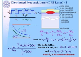
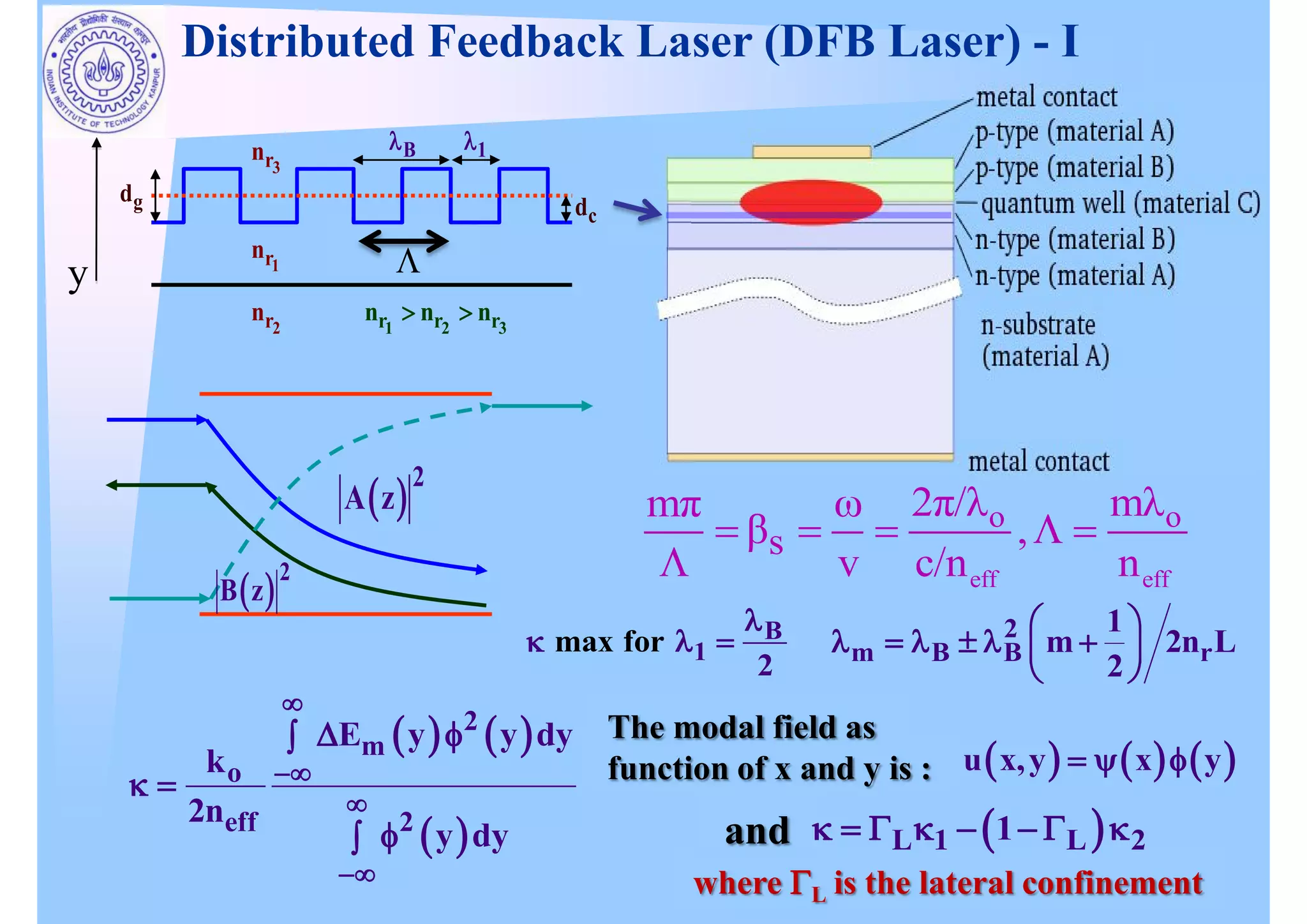
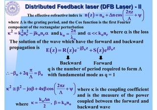
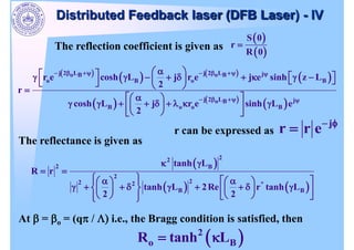
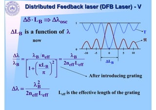
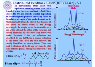
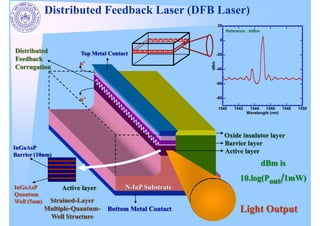
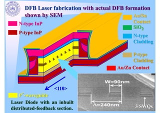
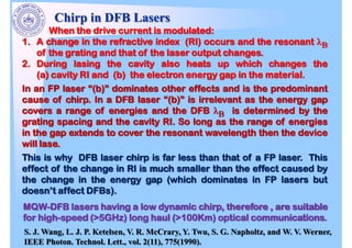
2
m
o
2
eff
E y y dy
k
2n
y dy
u x,y x y
2
A z
2
B z
2
m B B r
1
m 2n L
2
L 1 L 2
1
and
where L is the lateral confinement
B
1
max for
2
Distributed Feedback Laser (DFB Laser) - I
The modal field as
function of x and y is :
eff eff
o o
s
2
m
v c/n n
3
r
n
1
r
n
2
r
n
1 2 3
r r r
n n n
B 1
g
d
c
d
y
The effective refractive index is o
2 z
n z n ncos
2 2 2
o r o r
k n jk n o
o
2
k o r
k n where is the loss
The solution of the wave which have the forward and backward
propagation is
Distributed Feedback laser (DFB Laser) - II
o o
j z j z
E z R z e S z e
Backward Forward
o o
2q
where is the grating period, and the Cos function is the first Fourier
component of the rectangular perturbation
q is the number of period required to form
with fundamental mode as q = 1
2 2 2 z
j 4 cos where is the coupling coefficient
and is the measure of the power
coupled between the forward and
backward wave
and and
o
o o
k n
, k n
2
where
2 2
o
o
o
2
The phase mismatching factor is given as
eq
o
2n q
any is given by
Where q is the mode of back scattering and is the period of grating
eq
o B
1 1
2 n
Where B is the Bragg Wavelength,
where
B
1 q If q = 1 then
B =
If is the absorption coefficient (Loss)
z z
1 2
R z r e r e
z z
1 2
S z s e s e
and
2
2 2
j
2
S 0
r
R 0
The reflection coefficient is given as
Distributed Feedback laser (DFB Laser) - III
The reflection coefficient is given as
S 0
r
R 0
j 2 L j 2 L j
o B o B
o B o B
j 2 L j
o B
B o o B
r e cosh L j r e j e sinh z L
2
r
cosh L j r e sinh L e
2
j
r r e
r can be expressed as
2
2
2 B
2
2
2 2 *
B B
tanh L
R r
tanh L 2Re r tanh L
2 2
The reflectance is given as
At = o = (q / i.e., the Bragg condition is satisfied, then
2
o B
R tanh L
Distributed Feedback laser (DFB Laser) - IV
B osc
L
5
-5 10
-10 0
0
1
B
L
T
B is a functio f
L n o
now
B eff B
2
B eff eff
B
n
2n L
L
1
After introducing grating
2
B
eff eff
2n L Leff is the effective length of the grating
Distributed Feedback laser (DFB Laser) - V
phase slip
Phase slip =
g
d
L
2 2 4
B
1
max for
2
Distributed Feedback Laser (DFB Laser) - VI
In conventional DFB lasers two
equivalent standing waves exist (+1, -
1 modes) when there are no facet reflectivities.
One of the two are usually selected depending
on the corrugation phase at the cavity facets as
the relative strength of the mode depends on it.
Mathematically it can be shown that because of
the above no mode exists at the Bragg
wavelength. In simple terms the two reflectors,
one at the left and the other at the right are not
clearly identified by the wave and hence two
peaks. However if the two reflectors are
identified by one half being a mirror reflection
of the other half then the two mirrors are
clearly identified as shown below. Then one
peak is obtained at the Bragg wavelength, with
some satellite peaks. Main peak linewidth ~ 10s
of MHz
gL
L 1
Bragg Wavelength
Mode Gap
Power
output
gL
L 1
Power
output
Light Output
Bottom Metal Contact
Top Metal Contact
Oxide insulator layer
Barrier layer
Active layer
N-InP Substrate
InGaAsP
Barrier (10nm)
InGaAsP
Quantum
Well (5nm)
Active layer
p+
n+
Distributed
Feedback
Corrugation
Strained-Layer
Multiple-Quantum-
Well Structure
Distributed Feedback Laser (DFB Laser)
-80
-60
-40
-20
0
20
1540 1542 1544 1546 1548 1550
Wavelength (nm)
Reference : 0dBm
dBm is
10.log(Pout/1mW)
DFB Laser fabrication with actual DFB formation
shown by SEM
Laser Diode with an inbuilt
distributed-feedback section.
Au/Sn
Contact
N-type InP
P-type InP
SiO2
N-type
Cladding
P-type
Cladding
Au/Zn Contact
<110>
P--waveguide
3 SWQs
Chirp in DFB Lasers
S. J. Wang, L. J. P. Ketelsen, V. R. McCrary, Y. Twu, S. G. Napholtz, and W. V. Werner,
IEEE Photon. Technol. Lett., vol. 2(11), 775(1990).

Module ii dfb

  • 1.
    2 m o 2 eff E y ydy k 2n y dy u x,y x y 2 A z 2 B z 2 m B B r 1 m 2n L 2 L 1 L 2 1 and where L is the lateral confinement B 1 max for 2 Distributed Feedback Laser (DFB Laser) - I The modal field as function of x and y is : eff eff o o s 2 m v c/n n 3 r n 1 r n 2 r n 1 2 3 r r r n n n B 1 g d c d y
  • 2.
    The effective refractiveindex is o 2 z n z n ncos 2 2 2 o r o r k n jk n o o 2 k o r k n where is the loss The solution of the wave which have the forward and backward propagation is Distributed Feedback laser (DFB Laser) - II o o j z j z E z R z e S z e Backward Forward o o 2q where is the grating period, and the Cos function is the first Fourier component of the rectangular perturbation q is the number of period required to form with fundamental mode as q = 1 2 2 2 z j 4 cos where is the coupling coefficient and is the measure of the power coupled between the forward and backward wave and and o o o k n , k n 2 where
  • 3.
    2 2 o o o 2 The phasemismatching factor is given as eq o 2n q any is given by Where q is the mode of back scattering and is the period of grating eq o B 1 1 2 n Where B is the Bragg Wavelength, where B 1 q If q = 1 then B = If is the absorption coefficient (Loss) z z 1 2 R z r e r e z z 1 2 S z s e s e and 2 2 2 j 2 S 0 r R 0 The reflection coefficient is given as Distributed Feedback laser (DFB Laser) - III
  • 4.
    The reflection coefficientis given as S 0 r R 0 j 2 L j 2 L j o B o B o B o B j 2 L j o B B o o B r e cosh L j r e j e sinh z L 2 r cosh L j r e sinh L e 2 j r r e r can be expressed as 2 2 2 B 2 2 2 2 * B B tanh L R r tanh L 2Re r tanh L 2 2 The reflectance is given as At = o = (q / i.e., the Bragg condition is satisfied, then 2 o B R tanh L Distributed Feedback laser (DFB Laser) - IV
  • 5.
    B osc L 5 -5 10 -100 0 1 B L T B is a functio f L n o now B eff B 2 B eff eff B n 2n L L 1 After introducing grating 2 B eff eff 2n L Leff is the effective length of the grating Distributed Feedback laser (DFB Laser) - V
  • 6.
    phase slip Phase slip= g d L 2 2 4 B 1 max for 2 Distributed Feedback Laser (DFB Laser) - VI In conventional DFB lasers two equivalent standing waves exist (+1, - 1 modes) when there are no facet reflectivities. One of the two are usually selected depending on the corrugation phase at the cavity facets as the relative strength of the mode depends on it. Mathematically it can be shown that because of the above no mode exists at the Bragg wavelength. In simple terms the two reflectors, one at the left and the other at the right are not clearly identified by the wave and hence two peaks. However if the two reflectors are identified by one half being a mirror reflection of the other half then the two mirrors are clearly identified as shown below. Then one peak is obtained at the Bragg wavelength, with some satellite peaks. Main peak linewidth ~ 10s of MHz gL L 1 Bragg Wavelength Mode Gap Power output gL L 1 Power output
  • 7.
    Light Output Bottom MetalContact Top Metal Contact Oxide insulator layer Barrier layer Active layer N-InP Substrate InGaAsP Barrier (10nm) InGaAsP Quantum Well (5nm) Active layer p+ n+ Distributed Feedback Corrugation Strained-Layer Multiple-Quantum- Well Structure Distributed Feedback Laser (DFB Laser) -80 -60 -40 -20 0 20 1540 1542 1544 1546 1548 1550 Wavelength (nm) Reference : 0dBm dBm is 10.log(Pout/1mW)
  • 8.
    DFB Laser fabricationwith actual DFB formation shown by SEM Laser Diode with an inbuilt distributed-feedback section. Au/Sn Contact N-type InP P-type InP SiO2 N-type Cladding P-type Cladding Au/Zn Contact <110> P--waveguide 3 SWQs
  • 9.
    Chirp in DFBLasers S. J. Wang, L. J. P. Ketelsen, V. R. McCrary, Y. Twu, S. G. Napholtz, and W. V. Werner, IEEE Photon. Technol. Lett., vol. 2(11), 775(1990).