
Recommended
More Related Content
Similar to Migracion del pic 16f628a al pic microchip 40048a.pdf
Similar to Migracion del pic 16f628a al pic microchip 40048a.pdf (20)
More from Edwin4321
More from Edwin4321 (20)
Recently uploaded
Recently uploaded (20)
Migracion del pic 16f628a al pic microchip 40048a.pdf
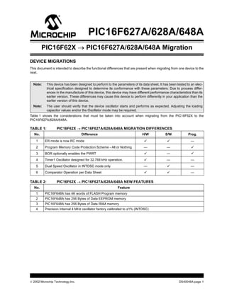
- 1. 2002 Microchip Technology Inc. DS40048A-page 1 PIC16F627A/628A/648A DEVICE MIGRATIONS This document is intended to describe the functional differences that are present when migrating from one device to the next. Table 1 shows the considerations that must be taken into account when migrating from the PIC16F62X to the PIC16F627A/628A/648A. TABLE 1: PIC16F62X → PIC16F627A/628A/648A MIGRATION DIFFERENCES TABLE 2: PIC16F62X → PIC16F627A/628A/648A NEW FEATURES Note: This device has been designed to perform to the parameters of its data sheet. It has been tested to an elec- trical specification designed to determine its conformance with these parameters. Due to process differ- ences in the manufacture of this device, this device may have different performance characteristics than its earlier version. These differences may cause this device to perform differently in your application than the earlier version of this device. Note: The user should verify that the device oscillator starts and performs as expected. Adjusting the loading capacitor values and/or the Oscillator mode may be required. No. Difference H/W S/W Prog. 1 ER mode is now RC mode — 2 Program Memory Code Protection Scheme - All or Nothing — — 3 BOR optionally enables the PWRT — 4 Timer1 Oscillator designed for 32.768 kHz operation. — — 5 Dual Speed Oscillator in INTOSC mode only — — 6 Comparator Operation per Data Sheet — No. Feature 1 PIC16F648A has 4K words of FLASH Program memory 2 PIC16F648A has 256 Bytes of Data EEPROM memory 3 PIC16F648A has 256 Bytes of Data RAM memory 4 Precision Internal 4 MHz oscillator factory calibrated to ±1% (INTOSC) PIC16F62X → PIC16F627A/628A/648A Migration
- 2. PIC16F62X DS40048A-page 2 2002 Microchip Technology Inc. DEVICE MIGRATIONS The PIC16F627A/628A/648A is mainly a technology process change from the PIC16F62X family of 18-pin parts with comparators. There are some changes that may affect older designs looking to use the new parts. The changes are grouped into two categories: those that affect hardware and those that affect software. In most cases, an older design will have little or no prob- lems migrating to these new parts. HARDWARE CHANGES ER Mode is now RC Mode The biggest difference between the PIC16F62X and the PIC16F627A/628A/648A is the removal of the ER Oscillator mode. This has been changed to an external Resistor/Capacitor (RC) mode. In most cases, a design can switch from ER to RC simply by adding a capacitor and changing the value of the resistor to provide the same clock speed. In cases where 37 kHz or 4 MHz is desired or acceptable, the external RC can be elimi- nated entirely and the Internal Oscillator modes can be used. FLASH Program Memory Code Protection Code Protection for the Program Memory has changed from Code Protect sections of memory to Code Protect of the whole memory. The Configuration bits12,10 CP0 and bits13,11 CP1 in the PIC16F62X do not exist in the PIC16F627A/628A/648A. They have been replaced with one configuration bit13 CP. New BOR PWRT Relationship Enabling Brown-out Reset (BOR) does not automati- cally enable the Power-up Timer (PWRT) the way it did in the PIC16F62X. Timer1 Oscillator Speed Change The Timer1 Oscillator is now designed for 32.768 kHz operation. In the PIC16F62X the Timer1 Oscillator was designed to run up to 200 kHz. Dual Speed Oscillator Mode Change The Dual Speed Oscillator mode only works within the INTOSC Oscillator mode. In the PIC16F62X, the Dual Speed Oscillator mode works in both the INTRC and ER Oscillator modes. Comparator Mode All comparator modes function as described in the data sheet. The issue described in the errata for the PIC16F62X has been rectified and is no longer an issue. Process Differences Because the PIC16F627A/628A/648A family uses a newer process technology, there will be subtle behavior differences between the PIC16F62X and the PIC16F627A/628A/648A parts. Before starting on a design migration, check the data sheets and verify that the electrical specifications for the new part are appro- priate for your application. TERMINOLOGY CHANGES 1. The “Brown-out Detect (BOD)” terminology has changed to “Brown-out Reset (BOR)” to better represent the function the Brown-out circuitry performs. 2. The “Internal RC Oscillator (INTRC)” terminol- ogy has changed to “Internal Oscillator (INTOSC)” to better represent the functioning of the circuitry.
- 3. 2002 Microchip Technology Inc. DS40048A - page 3 Information contained in this publication regarding device applications and the like is intended through suggestion only and may be superseded by updates. It is your responsibility to ensure that your application meets with your specifications. No representation or warranty is given and no liability is assumed by Microchip Technology Incorporated with respect to the accuracy or use of such information, or infringement of patents or other intellectual property rights arising from such use or otherwise. Use of Microchip’s products as critical com- ponents in life support systems is not authorized except with express written approval by Microchip. No licenses are con- veyed, implicitly or otherwise, under any intellectual property rights. Trademarks The Microchip name and logo, the Microchip logo, KEELOQ, MPLAB, PIC, PICmicro, PICSTART and PRO MATE are registered trademarks of Microchip Technology Incorporated in the U.S.A. and other countries. FilterLab, microID, MXDEV, MXLAB, PICMASTER, SEEVAL and The Embedded Control Solutions Company are registered trademarks of Microchip Technology Incorporated in the U.S.A. dsPIC, dsPICDEM.net, ECONOMONITOR, FanSense, FlexROM, fuzzyLAB, In-Circuit Serial Programming, ICSP, ICEPIC, microPort, Migratable Memory, MPASM, MPLIB, MPLINK, MPSIM, PICC, PICDEM, PICDEM.net, rfPIC, Select Mode and Total Endurance are trademarks of Microchip Technology Incorporated in the U.S.A. and other countries. Serialized Quick Turn Programming (SQTP) is a service mark of Microchip Technology Incorporated in the U.S.A. All other trademarks mentioned herein are property of their respective companies. © 2002, Microchip Technology Incorporated, Printed in the U.S.A., All Rights Reserved. Printed on recycled paper. Microchip received QS-9000 quality system certification for its worldwide headquarters, design and wafer fabrication facilities in Chandler and Tempe, Arizona in July 1999 and Mountain View, California in March 2002. The Company’s quality system processes and procedures are QS-9000 compliant for its PICmicro® 8-bit MCUs, KEELOQ® code hopping devices, Serial EEPROMs, microperipherals, non-volatile memory and analog products. In addition, Microchip’s quality system for the design and manufacture of development systems is ISO 9001 certified. Note the following details of the code protection feature on Microchip devices: • Microchip products meet the specification contained in their particular Microchip Data Sheet. • Microchip believes that its family of products is one of the most secure families of its kind on the market today, when used in the intended manner and under normal conditions. • There are dishonest and possibly illegal methods used to breach the code protection feature. All of these methods, to our knowl- edge, require using the Microchip products in a manner outside the operating specifications contained in Microchip's Data Sheets. Most likely, the person doing so is engaged in theft of intellectual property. • Microchip is willing to work with the customer who is concerned about the integrity of their code. • Neither Microchip nor any other semiconductor manufacturer can guarantee the security of their code. Code protection does not mean that we are guaranteeing the product as “unbreakable.” Code protection is constantly evolving. We at Microchip are committed to continuously improving the code protection features of our products.
- 4. DS40048A-page 4 2002 Microchip Technology Inc. AMERICAS Corporate Office 2355 West Chandler Blvd. Chandler, AZ 85224-6199 Tel: 480-792-7200 Fax: 480-792-7277 Technical Support: 480-792-7627 Web Address: http://www.microchip.com Rocky Mountain 2355 West Chandler Blvd. Chandler, AZ 85224-6199 Tel: 480-792-7966 Fax: 480-792-4338 Atlanta 3780 Mansell Road, Suite 130 Alpharetta, GA 30022 Tel: 770-640-0034 Fax: 770-640-0307 Boston 2 Lan Drive, Suite 120 Westford, MA 01886 Tel: 978-692-3848 Fax: 978-692-3821 Chicago 333 Pierce Road, Suite 180 Itasca, IL 60143 Tel: 630-285-0071 Fax: 630-285-0075 Dallas 4570 Westgrove Drive, Suite 160 Addison, TX 75001 Tel: 972-818-7423 Fax: 972-818-2924 Detroit Tri-Atria Office Building 32255 Northwestern Highway, Suite 190 Farmington Hills, MI 48334 Tel: 248-538-2250 Fax: 248-538-2260 Kokomo 2767 S. Albright Road Kokomo, Indiana 46902 Tel: 765-864-8360 Fax: 765-864-8387 Los Angeles 18201 Von Karman, Suite 1090 Irvine, CA 92612 Tel: 949-263-1888 Fax: 949-263-1338 San Jose Microchip Technology Inc. 2107 North First Street, Suite 590 San Jose, CA 95131 Tel: 408-436-7950 Fax: 408-436-7955 Toronto 6285 Northam Drive, Suite 108 Mississauga, Ontario L4V 1X5, Canada Tel: 905-673-0699 Fax: 905-673-6509 ASIA/PACIFIC Australia Microchip Technology Australia Pty Ltd Suite 22, 41 Rawson Street Epping 2121, NSW Australia Tel: 61-2-9868-6733 Fax: 61-2-9868-6755 China - Beijing Microchip Technology Consulting (Shanghai) Co., Ltd., Beijing Liaison Office Unit 915 Bei Hai Wan Tai Bldg. No. 6 Chaoyangmen Beidajie Beijing, 100027, No. China Tel: 86-10-85282100 Fax: 86-10-85282104 China - Chengdu Microchip Technology Consulting (Shanghai) Co., Ltd., Chengdu Liaison Office Rm. 2401-2402, 24th Floor, Ming Xing Financial Tower No. 88 TIDU Street Chengdu 610016, China Tel: 86-28-86766200 Fax: 86-28-86766599 China - Fuzhou Microchip Technology Consulting (Shanghai) Co., Ltd., Fuzhou Liaison Office Unit 28F, World Trade Plaza No. 71 Wusi Road Fuzhou 350001, China Tel: 86-591-7503506 Fax: 86-591-7503521 China - Hong Kong SAR Microchip Technology Hongkong Ltd. Unit 901-6, Tower 2, Metroplaza 223 Hing Fong Road Kwai Fong, N.T., Hong Kong Tel: 852-2401-1200 Fax: 852-2401-3431 China - Shanghai Microchip Technology Consulting (Shanghai) Co., Ltd. Room 701, Bldg. B Far East International Plaza No. 317 Xian Xia Road Shanghai, 200051 Tel: 86-21-6275-5700 Fax: 86-21-6275-5060 China - Shenzhen Microchip Technology Consulting (Shanghai) Co., Ltd., Shenzhen Liaison Office Rm. 1812, 18/F, Building A, United Plaza No. 5022 Binhe Road, Futian District Shenzhen 518033, China Tel: 86-755-82901380 Fax: 86-755-82966626 China - Qingdao Rm. B503, Fullhope Plaza, No. 12 Hong Kong Central Rd. Qingdao 266071, China Tel: 86-532-5027355 Fax: 86-532-5027205 India Microchip Technology Inc. India Liaison Office Divyasree Chambers 1 Floor, Wing A (A3/A4) No. 11, O’Shaugnessey Road Bangalore, 560 025, India Tel: 91-80-2290061 Fax: 91-80-2290062 Japan Microchip Technology Japan K.K. Benex S-1 6F 3-18-20, Shinyokohama Kohoku-Ku, Yokohama-shi Kanagawa, 222-0033, Japan Tel: 81-45-471- 6166 Fax: 81-45-471-6122 Korea Microchip Technology Korea 168-1, Youngbo Bldg. 3 Floor Samsung-Dong, Kangnam-Ku Seoul, Korea 135-882 Tel: 82-2-554-7200 Fax: 82-2-558-5934 Singapore Microchip Technology Singapore Pte Ltd. 200 Middle Road #07-02 Prime Centre Singapore, 188980 Tel: 65-6334-8870 Fax: 65-6334-8850 Taiwan Microchip Technology (Barbados) Inc., Taiwan Branch 11F-3, No. 207 Tung Hua North Road Taipei, 105, Taiwan Tel: 886-2-2717-7175 Fax: 886-2-2545-0139 EUROPE Austria Microchip Technology Austria GmbH Durisolstrasse 2 A-4600 Wels Austria Tel: 43-7242-2244-399 Fax: 43-7242-2244-393 Denmark Microchip Technology Nordic ApS Regus Business Centre Lautrup hoj 1-3 Ballerup DK-2750 Denmark Tel: 45 4420 9895 Fax: 45 4420 9910 France Microchip Technology SARL Parc d’Activite du Moulin de Massy 43 Rue du Saule Trapu Batiment A - ler Etage 91300 Massy, France Tel: 33-1-69-53-63-20 Fax: 33-1-69-30-90-79 Germany Microchip Technology GmbH Steinheilstrasse 10 D-85737 Ismaning, Germany Tel: 49-89-627-144 0 Fax: 49-89-627-144-44 Italy Microchip Technology SRL Centro Direzionale Colleoni Palazzo Taurus 1 V. Le Colleoni 1 20041 Agrate Brianza Milan, Italy Tel: 39-039-65791-1 Fax: 39-039-6899883 United Kingdom Microchip Ltd. 505 Eskdale Road Winnersh Triangle Wokingham Berkshire, England RG41 5TU Tel: 44 118 921 5869 Fax: 44-118 921-5820 12/05/02 WORLDWIDE SALES AND SERVICE