Downloaded 111 times
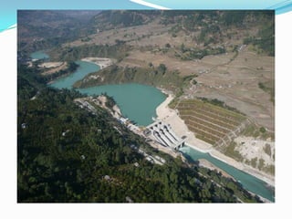
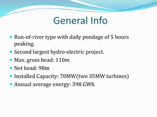
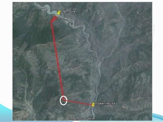
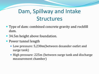


This document summarizes information about the 70 MW Middle Marsyangdi Hydropower Project located in Nepal. Key details include: - The powerhouse and headworks are located 14 km before Besisahar at an elevation of 760m. The dam site is 4 km before Besisahar. - Construction began in 2001 and was completed in 2007 with financial and technical support from Germany. - It has a run-of-river design with 5 hours of daily pondage. Installed capacity is 70MW from two 35MW turbines, with an annual average energy generation of 398 GWh. - The dam type is a combined concrete gravity and rockfill dam that is 34.5


