The document provides a tutorial on using Midas software to design a reinforced concrete building with flat slabs and walls. It describes 4 main steps:
1. Modeling and generating a mesh using the automesh tool.
2. Defining design parameters like loads, materials, and boundary conditions.
3. Designing columns based on the applied code.
4. Designing slabs and walls using the meshed slab/wall design tool to check flexure, shear, and reinforcement requirements. Screenshots demonstrate how to run analyses, view results, and update reinforcement based on the design checks.
This document provides an introduction to the CSiBridge software for modeling concrete box girder bridges. It describes the basic steps to create a bridge model, including defining the layout line, deck section, bridge object, and making assignments to spans, abutments, bents, and tendons. The example bridge modeled is a two-span prestressed concrete box girder bridge.
This document describes linking design and manufacturing on a PLM (Product Lifecycle Management) platform. Specifically, an automobile fuel tank cap was modeled in Creo Parametric. An injection mold was then developed for the part. The complete design data was integrated into Windchill PLM software for data and process management. Operations were generated to manufacture the mold cavities and core. The fuel tank cap design was then reviewed in the PLM software by a guest reviewer. This case study demonstrates how PLM software can efficiently manage product design and manufacturing data throughout the entire product lifecycle.
Linking design and manufacturing on a PLM platformiosrjce
IOSR Journal of Mechanical and Civil Engineering (IOSR-JMCE) is a double blind peer reviewed International Journal that provides rapid publication (within a month) of articles in all areas of mechanical and civil engineering and its applications. The journal welcomes publications of high quality papers on theoretical developments and practical applications in mechanical and civil engineering. Original research papers, state-of-the-art reviews, and high quality technical notes are invited for publications.
This document describes linking design and manufacturing on a PLM (Product Lifecycle Management) platform. Specifically, an automobile fuel tank cap was modeled in Creo Parametric. An injection mold was then developed for the part. The complete design data was integrated into Windchill PLM software for data and process management. The fuel tank cap design, mold design, and NC programs for manufacturing the mold were generated. The design data was then imported into Windchill where it could be accessed and reviewed by authorized users, including providing customer feedback. Integrating the design and manufacturing data onto a PLM platform allows for efficient management of the product data and process throughout the lifecycle.
EELE 5331 Digital ASIC DesignLab ManualDr. Yushi Zhou.docxtoltonkendal
This document outlines the procedures for a lab manual on digital ASIC design. It describes designing a single MOSFET transistor from schematic entry to post-layout simulation. Students are instructed on how to use Cadence software to create a schematic, perform pre-layout simulation using parametric and DC analysis, and generate layout of the transistor. The document provides step-by-step guidance on using key Cadence tools for simulation, layout, and verification of the transistor design.
IRJET - Knowledge-based Forging Die Design of CrankshaftIRJET Journal
The document describes a knowledge-based system for designing forging dies for crankshafts. The system uses knowledge bases containing relationships between design parameters like hammer load, dimensions, and flash size. It integrates CAD software to design the crankshaft and die models. Rules are applied at each design stage to help engineers make decisions. The system was tested on a crankshaft die design case study and showed benefits like reduced time/errors and improved quality compared to traditional CAD methods.
Optimization of sealing casting by identifying solidification defect and impr...IRJET Journal
1. The document discusses optimization of sealing castings through casting simulation. It aims to identify solidification defects in sealing castings and minimize them by optimizing the casting design using simulation software.
2. The current sealing casting design is analyzed using casting simulation software to identify solidification defects like shrinkage and misruns. Modifications are then made to the design using simulation to improve strength.
3. The methodology involves 3D modeling the casting, meshing it, applying material properties and boundary conditions in simulation software, and analyzing the results to identify defects and optimize the design.
IRJET- Finite Element Analysis of Winch Machine for Erection of Transmission ...IRJET Journal
The document discusses the design of a winch machine for erecting transmission towers. It begins with describing common methods for tower erection and their limitations. It then discusses the finite element method for simulation. The methodology section outlines the analytical design process for the winch drum and shaft based on loading calculations and standards. This includes selecting wire rope specifications and dimensions for the drum and shaft based on the load to be lifted. The analytical design calculations are shown. The design will then be modeled, simulated using finite element analysis, and experimentally tested to validate the simulation results. This will prove the loading conditions and design methodology.
IRJET- Thermal Load Effect on Exhaust Valve by using Conventional and Mix...IRJET Journal
This document summarizes a study that used computational fluid dynamics (CFD) to analyze the thermal load on an exhaust valve when using conventional fuels and mixed fuels in an internal combustion engine. The study used finite element analysis to model the temperature distribution and thermal stresses on an exhaust valve. CFD analysis was performed to determine the pressure drop, heat transfer coefficient, mass flow rate, and heat transfer rate for mixtures of methane and ethane at different volume fractions. The properties of the nanofluids created with different volume fractions of nanoparticles were calculated to be used as inputs for the thermal analysis of the exhaust valve.
Experimental Validation of 3-D Printed BoltsIJMERJOURNAL
ABSTRACT: 3-D printing, which is an automated production process with layer-by-layer control, has been gaining rapid development in recent years. 3-D printing is the process by which a 3-D digital design is converted into a component by depositing material using additive processing. Three dimensional (3D) printing offers versatile possibilities for adapting the structural parameters on engineering scaffolds. These three dimensional elements were produced from Poly Lactic Acid (PLA) and Acrylonitrile butadiene Styrene (ABS)by means of fused deposition process. This work is initiated by designing a three dimensional model of an ISO standard bolt and creating a 3D printing of this model using PLA and ABS as material. Designing will be carried out using SOLIDWORKS. Later on the design is analysed on analysis software (ANSYS) for deformation, equivalent stress and shear stress. A prototype model of this bolt will be created using three dimensional printer. Shear test is performed using UTM on the bolts that are created using three dimensional printer. Each bolt material’s failure forces are noted down and shear stresses are calculated. The PLA and ABS bolts are compared with each other. They are also checked for safe limits by comparing them with their respective material properties.
This document provides step-by-step instructions for modeling, analyzing, and designing a 10-story reinforced concrete building using ETABS. It describes creating the model grid and defining material properties. It also details drawing structural members like beams, columns, slabs, and shear walls and assigning section properties. The document specifies loading cases, analysis options, and design codes. It concludes with running analyses, design, and checking story drift. The overall objective is to demonstrate modeling and design of a reinforced concrete building using static lateral force procedure.
This document provides instructions for installing and configuring CIMtrek Discovery and Analysis (DNA) software. It explains that installation is simple and requires only a few mouse clicks. Configuration involves specifying an ignore list of standard Notes files and output file locations. The document also describes the discovery process, which interrogates Domino servers and Notes clients to compile a list of NSF files, analyzing each file's characteristics. Users can then view detailed information about forms, fields, scripts and more to understand applications before migration.
IRJET- Optimizing Cooling Efficiency through Conformal Cooling using Moldex3D...IRJET Journal
This document discusses optimizing cooling efficiency in injection molding through conformal cooling channel design using CAE simulation software. It begins with an introduction to injection molding and how cooling time significantly impacts manufacturing costs. The document then presents a case study where conformal cooling channels were designed for an automobile mudguard traditionally made via injection molding. Simulation analysis was conducted to compare conformal cooling results to traditional cooling, finding conformal cooling reduced cooling time from 38.6 to 26.8 seconds, improved cooling efficiency from 7.37% to 89.8%, and decreased warpage and part defects. The conformal cooling design was found to optimize part quality and cooling time through more uniform heat removal.
This document presents a traffic sign recognition system using a convolutional neural network (CNN) model. The authors train the CNN model on a German traffic sign dataset containing over 50,000 images across 43 classes. The proposed CNN architecture contains 4 VGGNet blocks with convolutional, max pooling, dropout and batch normalization layers. The model is trained for 45 epochs and achieves 96.9% accuracy and 11.4% test loss on the test set, outperforming other baseline models. The trained CNN model can accurately classify traffic sign images to assist with applications like self-driving cars.
SPUR GEAR DEVELOPMENT USING ADDITIVE MANUFACTURING TECHNIQUESIRJET Journal
This document discusses developing spur gears using additive manufacturing techniques. It proposes suitable additive techniques and materials for manufacturing mechanical gears. The study prepares a gear model to perform structural stress analysis. Fused deposition modeling is identified as a method to produce functional tooling for manufacturing spur gears. The document also compares the manufacturing cost and feasible batch size of additive manufacturing versus injection molding for large-scale production. The goal is to use additive manufacturing instead of injection molding when small production volumes are required to reduce cost and time.
Extendable additional steps for busses and trucksIRJET Journal
This document describes the design of extendable additional steps for buses and trucks. It aims to reduce knee pain for passengers when boarding vehicles with high steps. The design process included generating conceptual sketches, selecting a final design using a weighted matrix, and modeling the design in CAD software. A structural analysis was conducted to evaluate stresses and deformations. The final design consists of a base frame, links, steps, piston, and cylinder that can extend and retract the additional steps. The analysis found the maximum deformation and stresses were within automotive industry standards. Drawings and bills of materials were also provided. In conclusion, the extendable additional steps were designed and analyzed to help reduce knee pain when boarding buses and trucks.
This document provides instructions for a tutorial on generative part stress analysis using CATIA V5. The tutorial is intended to last 45 minutes and cover part design and knowledge advisor capabilities. It describes the 7 major steps, which include designing a wheel rim, renaming parameters, adding formulas to constraints, creating user parameters and formulas, adding a rule and check, and creating design tables to compute inertia elements. It also provides information on setting up the appropriate CATIA settings and material catalog for the tutorial.
IRJET- Design and Development Pedal Operated Multi-Crop Thresher with Vibrati...IRJET Journal
This document summarizes the design and development of a pedal-operated multi-crop thresher with a vibrating screen and maize de-seeder. The machine was designed to thresh, separate, and clean grains using only human power from pedals. It has a threshing unit that separates grains from plants using high-speed rotational blades powered by a pedal mechanism. The design aims to make a simple, compact, and ergonomic machine that can be comfortably operated by men or women. The document describes the machine's components and operation, and evaluates its threshing and cleaning efficiency and grain loss.
To develop a controller with a unique set of functions, which is capable of operating in harsh environments (wide temperature range, electromagnetic interferences, etc.) as well as simple to use, is a difficult job.
Deployment of Debug and Trace for features in RISC-V CoreIRJET Journal
1) The document discusses verification and debugging techniques for RISC-V cores, specifically using instruction and data tracing.
2) It describes the phases of verification including test planning, testbench building, test writing, code coverage analysis, and debugging.
3) Debugging with tracing allows reconstructing the program flow by decoding traced instruction and data accesses and comparing them to the simulation flow to check for errors.
This document summarizes a research paper on an airport management system using face recognition. It discusses:
1) Developing a face recognition-based attendance tracking system to improve efficiency over previous systems.
2) Creating face databases to train the recognition algorithm to identify passengers during check-in.
3) The system automatically records attendance by identifying faces, displaying passenger IDs and names, and saving records.
[SiriusCon 2020] Realization of Model-Based Safety Analysis and Integration w...Obeo
The importance of mission or safety-critical software systems in many application domains of embedded systems is continuously growing, and so is the effort and complexity for reliability and safety analysis. Model-based system engineering (MBSE) is currently one of the key approaches to cope with increasing system complexity.
With Component Fault Trees (CFTs) there is a model- and component-based methodology for safety analysis, which extends the advantages of model-based development to safety & reliability engineering. In this talk, we demonstrate how to ease the development of safety-critical systems by implementing a graphical modeling tool for Component Fault Trees using Sirius and integrate safety analysis capabilities in a model-based system engineering workflow in Capella.
Speaker :
Mark Zeller, Siemens CT
Marc Zeller works as a Senior Key Expert for model-based safety and reliability engineering at Siemens Corporate Technology. His research interests are focused on the efficient and effective development of dependability-relevant Cyber-physical Systems using model-based engineering techniques. Marc Zeller received a diploma in Computer Science from the Karlsruhe Institute of Technology (KIT) in 2007 and obtained a PhD in Computer Science from the University of Augsburg in 2013. With over 10-years' experience in different industrial domains, such as automotive, railway, avionics, or industry automations, he has been involved in various projects establishing model-based engineering techniques and is author of many publications in this area.
The document discusses the design of a fixture to control defects in capacitors during mass production. During the resin filling and curing process, the terminals and flatness of capacitors can become distorted, violating specifications. To address this, a fixture was designed to accurately locate and secure the capacitor during resin curing to maintain the terminal heights and flatness. The fixture design process included CAD modeling, detailing, material selection of aluminum, CNC manufacturing, and validation testing to ensure the fixture locates the capacitor properly to eliminate defects. The fixture aims to increase production quality and reduce failure rates during capacitor assembly.
This document provides an overview and step-by-step instructions for performing a linear time history analysis in MIDAS Gen. The analysis involves defining model properties, creating frame elements, applying loads and boundary conditions, performing an eigenvalue analysis, and evaluating results such as displacements, member forces, and time history graphs. Key steps include assigning material and section properties, generating the frame model, defining static and time history load cases, converting loads to masses, specifying analysis control data, and reviewing output.
This document provides a quick-start guide for connecting various Weintek I/O modules to CODESYS using a cMT-X HMI device. It outlines the steps to set up CODESYS, create a project, scan for devices, add specific Weintek devices like iR-ETN, iR-COP, and iR-ECAT, and map I/O tags between the modules and CODESYS project. The guide is intended to help users get started integrating Weintek I/O with CODESYS control programming.
Using recycled concrete aggregates (RCA) for pavements is crucial to achieving sustainability. Implementing RCA for new pavement can minimize carbon footprint, conserve natural resources, reduce harmful emissions, and lower life cycle costs. Compared to natural aggregate (NA), RCA pavement has fewer comprehensive studies and sustainability assessments.
More Related Content
Similar to MIDAS CIVIL Tendon template for prestressing
Optimization of sealing casting by identifying solidification defect and impr...IRJET Journal
1. The document discusses optimization of sealing castings through casting simulation. It aims to identify solidification defects in sealing castings and minimize them by optimizing the casting design using simulation software.
2. The current sealing casting design is analyzed using casting simulation software to identify solidification defects like shrinkage and misruns. Modifications are then made to the design using simulation to improve strength.
3. The methodology involves 3D modeling the casting, meshing it, applying material properties and boundary conditions in simulation software, and analyzing the results to identify defects and optimize the design.
IRJET- Finite Element Analysis of Winch Machine for Erection of Transmission ...IRJET Journal
The document discusses the design of a winch machine for erecting transmission towers. It begins with describing common methods for tower erection and their limitations. It then discusses the finite element method for simulation. The methodology section outlines the analytical design process for the winch drum and shaft based on loading calculations and standards. This includes selecting wire rope specifications and dimensions for the drum and shaft based on the load to be lifted. The analytical design calculations are shown. The design will then be modeled, simulated using finite element analysis, and experimentally tested to validate the simulation results. This will prove the loading conditions and design methodology.
IRJET- Thermal Load Effect on Exhaust Valve by using Conventional and Mix...IRJET Journal
This document summarizes a study that used computational fluid dynamics (CFD) to analyze the thermal load on an exhaust valve when using conventional fuels and mixed fuels in an internal combustion engine. The study used finite element analysis to model the temperature distribution and thermal stresses on an exhaust valve. CFD analysis was performed to determine the pressure drop, heat transfer coefficient, mass flow rate, and heat transfer rate for mixtures of methane and ethane at different volume fractions. The properties of the nanofluids created with different volume fractions of nanoparticles were calculated to be used as inputs for the thermal analysis of the exhaust valve.
Experimental Validation of 3-D Printed BoltsIJMERJOURNAL
ABSTRACT: 3-D printing, which is an automated production process with layer-by-layer control, has been gaining rapid development in recent years. 3-D printing is the process by which a 3-D digital design is converted into a component by depositing material using additive processing. Three dimensional (3D) printing offers versatile possibilities for adapting the structural parameters on engineering scaffolds. These three dimensional elements were produced from Poly Lactic Acid (PLA) and Acrylonitrile butadiene Styrene (ABS)by means of fused deposition process. This work is initiated by designing a three dimensional model of an ISO standard bolt and creating a 3D printing of this model using PLA and ABS as material. Designing will be carried out using SOLIDWORKS. Later on the design is analysed on analysis software (ANSYS) for deformation, equivalent stress and shear stress. A prototype model of this bolt will be created using three dimensional printer. Shear test is performed using UTM on the bolts that are created using three dimensional printer. Each bolt material’s failure forces are noted down and shear stresses are calculated. The PLA and ABS bolts are compared with each other. They are also checked for safe limits by comparing them with their respective material properties.
This document provides step-by-step instructions for modeling, analyzing, and designing a 10-story reinforced concrete building using ETABS. It describes creating the model grid and defining material properties. It also details drawing structural members like beams, columns, slabs, and shear walls and assigning section properties. The document specifies loading cases, analysis options, and design codes. It concludes with running analyses, design, and checking story drift. The overall objective is to demonstrate modeling and design of a reinforced concrete building using static lateral force procedure.
This document provides instructions for installing and configuring CIMtrek Discovery and Analysis (DNA) software. It explains that installation is simple and requires only a few mouse clicks. Configuration involves specifying an ignore list of standard Notes files and output file locations. The document also describes the discovery process, which interrogates Domino servers and Notes clients to compile a list of NSF files, analyzing each file's characteristics. Users can then view detailed information about forms, fields, scripts and more to understand applications before migration.
IRJET- Optimizing Cooling Efficiency through Conformal Cooling using Moldex3D...IRJET Journal
This document discusses optimizing cooling efficiency in injection molding through conformal cooling channel design using CAE simulation software. It begins with an introduction to injection molding and how cooling time significantly impacts manufacturing costs. The document then presents a case study where conformal cooling channels were designed for an automobile mudguard traditionally made via injection molding. Simulation analysis was conducted to compare conformal cooling results to traditional cooling, finding conformal cooling reduced cooling time from 38.6 to 26.8 seconds, improved cooling efficiency from 7.37% to 89.8%, and decreased warpage and part defects. The conformal cooling design was found to optimize part quality and cooling time through more uniform heat removal.
This document presents a traffic sign recognition system using a convolutional neural network (CNN) model. The authors train the CNN model on a German traffic sign dataset containing over 50,000 images across 43 classes. The proposed CNN architecture contains 4 VGGNet blocks with convolutional, max pooling, dropout and batch normalization layers. The model is trained for 45 epochs and achieves 96.9% accuracy and 11.4% test loss on the test set, outperforming other baseline models. The trained CNN model can accurately classify traffic sign images to assist with applications like self-driving cars.
SPUR GEAR DEVELOPMENT USING ADDITIVE MANUFACTURING TECHNIQUESIRJET Journal
This document discusses developing spur gears using additive manufacturing techniques. It proposes suitable additive techniques and materials for manufacturing mechanical gears. The study prepares a gear model to perform structural stress analysis. Fused deposition modeling is identified as a method to produce functional tooling for manufacturing spur gears. The document also compares the manufacturing cost and feasible batch size of additive manufacturing versus injection molding for large-scale production. The goal is to use additive manufacturing instead of injection molding when small production volumes are required to reduce cost and time.
Extendable additional steps for busses and trucksIRJET Journal
This document describes the design of extendable additional steps for buses and trucks. It aims to reduce knee pain for passengers when boarding vehicles with high steps. The design process included generating conceptual sketches, selecting a final design using a weighted matrix, and modeling the design in CAD software. A structural analysis was conducted to evaluate stresses and deformations. The final design consists of a base frame, links, steps, piston, and cylinder that can extend and retract the additional steps. The analysis found the maximum deformation and stresses were within automotive industry standards. Drawings and bills of materials were also provided. In conclusion, the extendable additional steps were designed and analyzed to help reduce knee pain when boarding buses and trucks.
This document provides instructions for a tutorial on generative part stress analysis using CATIA V5. The tutorial is intended to last 45 minutes and cover part design and knowledge advisor capabilities. It describes the 7 major steps, which include designing a wheel rim, renaming parameters, adding formulas to constraints, creating user parameters and formulas, adding a rule and check, and creating design tables to compute inertia elements. It also provides information on setting up the appropriate CATIA settings and material catalog for the tutorial.
IRJET- Design and Development Pedal Operated Multi-Crop Thresher with Vibrati...IRJET Journal
This document summarizes the design and development of a pedal-operated multi-crop thresher with a vibrating screen and maize de-seeder. The machine was designed to thresh, separate, and clean grains using only human power from pedals. It has a threshing unit that separates grains from plants using high-speed rotational blades powered by a pedal mechanism. The design aims to make a simple, compact, and ergonomic machine that can be comfortably operated by men or women. The document describes the machine's components and operation, and evaluates its threshing and cleaning efficiency and grain loss.
To develop a controller with a unique set of functions, which is capable of operating in harsh environments (wide temperature range, electromagnetic interferences, etc.) as well as simple to use, is a difficult job.
Deployment of Debug and Trace for features in RISC-V CoreIRJET Journal
1) The document discusses verification and debugging techniques for RISC-V cores, specifically using instruction and data tracing.
2) It describes the phases of verification including test planning, testbench building, test writing, code coverage analysis, and debugging.
3) Debugging with tracing allows reconstructing the program flow by decoding traced instruction and data accesses and comparing them to the simulation flow to check for errors.
This document summarizes a research paper on an airport management system using face recognition. It discusses:
1) Developing a face recognition-based attendance tracking system to improve efficiency over previous systems.
2) Creating face databases to train the recognition algorithm to identify passengers during check-in.
3) The system automatically records attendance by identifying faces, displaying passenger IDs and names, and saving records.
[SiriusCon 2020] Realization of Model-Based Safety Analysis and Integration w...Obeo
The importance of mission or safety-critical software systems in many application domains of embedded systems is continuously growing, and so is the effort and complexity for reliability and safety analysis. Model-based system engineering (MBSE) is currently one of the key approaches to cope with increasing system complexity.
With Component Fault Trees (CFTs) there is a model- and component-based methodology for safety analysis, which extends the advantages of model-based development to safety & reliability engineering. In this talk, we demonstrate how to ease the development of safety-critical systems by implementing a graphical modeling tool for Component Fault Trees using Sirius and integrate safety analysis capabilities in a model-based system engineering workflow in Capella.
Speaker :
Mark Zeller, Siemens CT
Marc Zeller works as a Senior Key Expert for model-based safety and reliability engineering at Siemens Corporate Technology. His research interests are focused on the efficient and effective development of dependability-relevant Cyber-physical Systems using model-based engineering techniques. Marc Zeller received a diploma in Computer Science from the Karlsruhe Institute of Technology (KIT) in 2007 and obtained a PhD in Computer Science from the University of Augsburg in 2013. With over 10-years' experience in different industrial domains, such as automotive, railway, avionics, or industry automations, he has been involved in various projects establishing model-based engineering techniques and is author of many publications in this area.
The document discusses the design of a fixture to control defects in capacitors during mass production. During the resin filling and curing process, the terminals and flatness of capacitors can become distorted, violating specifications. To address this, a fixture was designed to accurately locate and secure the capacitor during resin curing to maintain the terminal heights and flatness. The fixture design process included CAD modeling, detailing, material selection of aluminum, CNC manufacturing, and validation testing to ensure the fixture locates the capacitor properly to eliminate defects. The fixture aims to increase production quality and reduce failure rates during capacitor assembly.
This document provides an overview and step-by-step instructions for performing a linear time history analysis in MIDAS Gen. The analysis involves defining model properties, creating frame elements, applying loads and boundary conditions, performing an eigenvalue analysis, and evaluating results such as displacements, member forces, and time history graphs. Key steps include assigning material and section properties, generating the frame model, defining static and time history load cases, converting loads to masses, specifying analysis control data, and reviewing output.
This document provides a quick-start guide for connecting various Weintek I/O modules to CODESYS using a cMT-X HMI device. It outlines the steps to set up CODESYS, create a project, scan for devices, add specific Weintek devices like iR-ETN, iR-COP, and iR-ECAT, and map I/O tags between the modules and CODESYS project. The guide is intended to help users get started integrating Weintek I/O with CODESYS control programming.
Similar to MIDAS CIVIL Tendon template for prestressing (20)
Using recycled concrete aggregates (RCA) for pavements is crucial to achieving sustainability. Implementing RCA for new pavement can minimize carbon footprint, conserve natural resources, reduce harmful emissions, and lower life cycle costs. Compared to natural aggregate (NA), RCA pavement has fewer comprehensive studies and sustainability assessments.
Advanced control scheme of doubly fed induction generator for wind turbine us...IJECEIAES
This paper describes a speed control device for generating electrical energy on an electricity network based on the doubly fed induction generator (DFIG) used for wind power conversion systems. At first, a double-fed induction generator model was constructed. A control law is formulated to govern the flow of energy between the stator of a DFIG and the energy network using three types of controllers: proportional integral (PI), sliding mode controller (SMC) and second order sliding mode controller (SOSMC). Their different results in terms of power reference tracking, reaction to unexpected speed fluctuations, sensitivity to perturbations, and resilience against machine parameter alterations are compared. MATLAB/Simulink was used to conduct the simulations for the preceding study. Multiple simulations have shown very satisfying results, and the investigations demonstrate the efficacy and power-enhancing capabilities of the suggested control system.
DEEP LEARNING FOR SMART GRID INTRUSION DETECTION: A HYBRID CNN-LSTM-BASED MODELgerogepatton
As digital technology becomes more deeply embedded in power systems, protecting the communication
networks of Smart Grids (SG) has emerged as a critical concern. Distributed Network Protocol 3 (DNP3)
represents a multi-tiered application layer protocol extensively utilized in Supervisory Control and Data
Acquisition (SCADA)-based smart grids to facilitate real-time data gathering and control functionalities.
Robust Intrusion Detection Systems (IDS) are necessary for early threat detection and mitigation because
of the interconnection of these networks, which makes them vulnerable to a variety of cyberattacks. To
solve this issue, this paper develops a hybrid Deep Learning (DL) model specifically designed for intrusion
detection in smart grids. The proposed approach is a combination of the Convolutional Neural Network
(CNN) and the Long-Short-Term Memory algorithms (LSTM). We employed a recent intrusion detection
dataset (DNP3), which focuses on unauthorized commands and Denial of Service (DoS) cyberattacks, to
train and test our model. The results of our experiments show that our CNN-LSTM method is much better
at finding smart grid intrusions than other deep learning algorithms used for classification. In addition,
our proposed approach improves accuracy, precision, recall, and F1 score, achieving a high detection
accuracy rate of 99.50%.
Introduction- e - waste – definition - sources of e-waste– hazardous substances in e-waste - effects of e-waste on environment and human health- need for e-waste management– e-waste handling rules - waste minimization techniques for managing e-waste – recycling of e-waste - disposal treatment methods of e- waste – mechanism of extraction of precious metal from leaching solution-global Scenario of E-waste – E-waste in India- case studies.
CHINA’S GEO-ECONOMIC OUTREACH IN CENTRAL ASIAN COUNTRIES AND FUTURE PROSPECTjpsjournal1
The rivalry between prominent international actors for dominance over Central Asia's hydrocarbon
reserves and the ancient silk trade route, along with China's diplomatic endeavours in the area, has been
referred to as the "New Great Game." This research centres on the power struggle, considering
geopolitical, geostrategic, and geoeconomic variables. Topics including trade, political hegemony, oil
politics, and conventional and nontraditional security are all explored and explained by the researcher.
Using Mackinder's Heartland, Spykman Rimland, and Hegemonic Stability theories, examines China's role
in Central Asia. This study adheres to the empirical epistemological method and has taken care of
objectivity. This study analyze primary and secondary research documents critically to elaborate role of
china’s geo economic outreach in central Asian countries and its future prospect. China is thriving in trade,
pipeline politics, and winning states, according to this study, thanks to important instruments like the
Shanghai Cooperation Organisation and the Belt and Road Economic Initiative. According to this study,
China is seeing significant success in commerce, pipeline politics, and gaining influence on other
governments. This success may be attributed to the effective utilisation of key tools such as the Shanghai
Cooperation Organisation and the Belt and Road Economic Initiative.
We have compiled the most important slides from each speaker's presentation. This year’s compilation, available for free, captures the key insights and contributions shared during the DfMAy 2024 conference.
International Conference on NLP, Artificial Intelligence, Machine Learning an...gerogepatton
International Conference on NLP, Artificial Intelligence, Machine Learning and Applications (NLAIM 2024) offers a premier global platform for exchanging insights and findings in the theory, methodology, and applications of NLP, Artificial Intelligence, Machine Learning, and their applications. The conference seeks substantial contributions across all key domains of NLP, Artificial Intelligence, Machine Learning, and their practical applications, aiming to foster both theoretical advancements and real-world implementations. With a focus on facilitating collaboration between researchers and practitioners from academia and industry, the conference serves as a nexus for sharing the latest developments in the field.
6th International Conference on Machine Learning & Applications (CMLA 2024)ClaraZara1
6th International Conference on Machine Learning & Applications (CMLA 2024) will provide an excellent international forum for sharing knowledge and results in theory, methodology and applications of on Machine Learning & Applications.
Presentation of IEEE Slovenia CIS (Computational Intelligence Society) Chapte...University of Maribor
Slides from talk presenting:
Aleš Zamuda: Presentation of IEEE Slovenia CIS (Computational Intelligence Society) Chapter and Networking.
Presentation at IcETRAN 2024 session:
"Inter-Society Networking Panel GRSS/MTT-S/CIS
Panel Session: Promoting Connection and Cooperation"
IEEE Slovenia GRSS
IEEE Serbia and Montenegro MTT-S
IEEE Slovenia CIS
11TH INTERNATIONAL CONFERENCE ON ELECTRICAL, ELECTRONIC AND COMPUTING ENGINEERING
3-6 June 2024, Niš, Serbia
Low power architecture of logic gates using adiabatic techniquesnooriasukmaningtyas
The growing significance of portable systems to limit power consumption in ultra-large-scale-integration chips of very high density, has recently led to rapid and inventive progresses in low-power design. The most effective technique is adiabatic logic circuit design in energy-efficient hardware. This paper presents two adiabatic approaches for the design of low power circuits, modified positive feedback adiabatic logic (modified PFAL) and the other is direct current diode based positive feedback adiabatic logic (DC-DB PFAL). Logic gates are the preliminary components in any digital circuit design. By improving the performance of basic gates, one can improvise the whole system performance. In this paper proposed circuit design of the low power architecture of OR/NOR, AND/NAND, and XOR/XNOR gates are presented using the said approaches and their results are analyzed for powerdissipation, delay, power-delay-product and rise time and compared with the other adiabatic techniques along with the conventional complementary metal oxide semiconductor (CMOS) designs reported in the literature. It has been found that the designs with DC-DB PFAL technique outperform with the percentage improvement of 65% for NOR gate and 7% for NAND gate and 34% for XNOR gate over the modified PFAL techniques at 10 MHz respectively.
Low power architecture of logic gates using adiabatic techniques
MIDAS CIVIL Tendon template for prestressing
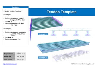
1. Contents
What is Tendon Template?
Example 1
- Model: A single span integral
bridge with TY section
- Unit: kN, m
- Section: Composite-PSC with
TY7, TYE7
Example 2
- Model: A single span bridge with
AASHTO PCI bulb Tee
section
- Unit: kips, in
- Section: Composite PSC I
Tendon Template
MIDAS Information Technology Co., Ltd.
http://en.midasuser.com
Program Version Civil 2015 (v1.1)
Release Date July, 14, 2014
Latest Revision Dec., 10, 2014
Example 1
Example 2
2. MIDAS Information Technology Co., Ltd.
http://en.midasuser.com
Civil 2015 (v1.1)
1/26
What is Tendon Template?
Step
00
Tendon layout Tendon Profile
Section database with strands
for precast girders
Typical tendon layout
Auto-Generation
Tendon Template is a function to create tendon profile more easily using typical tendon layout and Auto-Generation.
3. MIDAS Information Technology Co., Ltd.
http://en.midasuser.com
Civil 2015 (v1.1)
2/26
What is Tendon Template?
Step
00
Various profiles of strands/tendons for the prestressed girders can be created using Tendon Template with ease.
Auto-generation of the UK PSC section database.
Straight tendons and harped tendons can be defined based on the span and section information.
The tendon layouts generated in a project can be used to other similar projects which have the same tendon layout but different span lengths
by exporting & importing tendon template data.
Structure tab > Wizard > PSC Bridge > Tendon Template
Tendon Template Add/Modify Tendon Template
4. MIDAS Information Technology Co., Ltd.
http://en.midasuser.com
Civil 2015 (v1.1)
3/26
Section database for Auto-Generation of strands
Step
00
PSC Value Section DB
UK-M
PSC DB in UK Code
UK-Soild Box
UK-TY
UK-SYE
UK-U_SU
UK-Y UK-YE
UK-TY(Rebate)
UK-SY
UK-MYE
UK-MY
UK-UMB
UK-T
UK-TYE(Rebate) UK-TYE
UK-W
5. MIDAS Information Technology Co., Ltd.
http://en.midasuser.com
Civil 2015 (v1.1)
4/26
Bridge cross-section
TY 7 section dimensions
Bridge overview
Bridge type: A single span composite
integral bridge with 22 degree skew
Span length: 12.4 m
Ten girders spaced at 1.5 m
Composite section with TY7 beam
Example 1 : Bridge overview
Step
01
TYE 7 section dimensions
6. MIDAS Information Technology Co., Ltd.
http://en.midasuser.com
Civil 2015 (v1.1)
5/26
Step
01 Open the model file
Open
1
2
3
1. Click .
2. Select [22 S_Span Integral_TYsec.mcb].
3. Click the [Open] button.
7. MIDAS Information Technology Co., Ltd.
http://en.midasuser.com
Civil 2015 (v1.1)
6/26
Sections for precast girders
Step
02
PSC-Value section
Standard TY7
Standard TYE7 Standard TYE7-1
These sections are already defined in the model file.
8. MIDAS Information Technology Co., Ltd.
http://en.midasuser.com
Civil 2015 (v1.1)
7/26
Composite sections with cast-in-place concrete slab
Step
02
Composite-PSC section type
Interior
composite
girders
9. MIDAS Information Technology Co., Ltd.
http://en.midasuser.com
Civil 2015 (v1.1)
8/26
Composite sections with cast-in-place concrete slab
Step
02
Composite-PSC section type
Left exterior
composite girder
Right exterior
composite girder
10. MIDAS Information Technology Co., Ltd.
http://en.midasuser.com
Civil 2015 (v1.1)
9/26
Step
03 Define strands using Tendon Template…
Define Tendon Template
Structure > Wizard > PSC Bridge >
Tendon Template…
1. [Use Prefix Name]: R
2. Select the right exterior girder for [Assigned
Elements].
3. Click the [Auto Generation] button.
4. Click the [OK] button.
2
1
3
4
A preview of the tendon profile is viewed from
the assigned elements.
1
11. MIDAS Information Technology Co., Ltd.
http://en.midasuser.com
Civil 2015 (v1.1)
10/26
Step
03 Define strands using Tendon Template…
Define Tendon Template
1
2
3
3
4
1
1. Tendon > Plan view, Elevation view
2. Tendon > Section >28
3. Check strand arrangement.
4. Click the [OK] button.
3
2: Tendon profile can be selected by clicking
in the list or drag the tendon in display view
1
1: All the strands defined in Tendon
Template are transferred to “Load >
Temp./Prestress > Tendon Profile.
2
12. MIDAS Information Technology Co., Ltd.
http://en.midasuser.com
Civil 2015 (v1.1)
11/26
Step
03
Define Tendon Template
2
1
Define strands using Tendon Template…
Structure > Wizard > PSC Bridge >
Tendon Template…
1. [Use Prefix Name]: L
2. Select the left exterior girder for [Assigned
Elements].
3. Click the [Auto Generation] button.
4. Click the [OK] button.
5. Click the [OK] button.
Any generated strand can be selected from Tendon
Template List or Tendon Template View (plan view,
elevation view and section view).
1
4
5
3
13. MIDAS Information Technology Co., Ltd.
http://en.midasuser.com
Civil 2015 (v1.1)
12/26
Step
03
Define Tendon Template
1. [Use Prefix Name]: MID
2. Select the elements corresponding to an interior
girder for [Assigned Elements].
3. Click the [Add] button.
4. Repeat 8 times above process (2 and 3) for the
remaining interior girders.
5. Click the [Auto Generation] button.
6. Click the [OK] button.
7. Click the [OK] button.
Define strands using Tendon Template…
2 3
1
6
1
2
4
1: This is useful when assigning identical arrangement
of strands to many girders.
5
14. MIDAS Information Technology Co., Ltd.
http://en.midasuser.com
Civil 2015 (v1.1)
13/26
Step
04 Generated tendon profiles
Check tendon profile
1. Select tendon profile from Works Tree.
2. Display tendon profile by right-clicking and
selecting [Display].
3. Load > Load Type > Temp./Prestress
4. Select : [Tendon Profile].
5. Check the list of tendon profiles.
2
5
4
15. MIDAS Information Technology Co., Ltd.
http://en.midasuser.com
Civil 2015 (v1.1)
14/26
Bridge cross-section
Dimensions
Bridge overview
Bridge type: A straight bridge with no skew
Span length: A single Span 120.0 ft
Six precast spaced at 9.0 ft
Total deck width: 51.0 ft
Precast beams : AASHTO PCI bulb-Tee
Example 2 : Bridge overview
Step
00
16. MIDAS Information Technology Co., Ltd.
http://en.midasuser.com
Civil 2015 (v1.1)
15/26
Strand pattern
Longitudinal strand profile
Strand data
Example 2 : Bridge overview
Step
00
Area of one strand: 0.153 in2
Ultimate strength (fpu): 270.0 ksi
Yield strength (fpy): 243.0 ksi
In this example, 12 harped strands and 36
straight strands will be represented by an
equivalent strand separately.
17. MIDAS Information Technology Co., Ltd.
http://en.midasuser.com
Civil 2015 (v1.1)
16/26
Step
01 Open the model file
Open
1
2
3
1. Click .
2. Select [22 S_Span PCI bulb_Tsec.mcb].
3. Click the [Open] button.
18. MIDAS Information Technology Co., Ltd.
http://en.midasuser.com
Civil 2015 (v1.1)
17/26
Composite sections
Step
02
Composite-I section type
Interior composite girders
Exterior composite girders
These sections are already defined in the model file.
19. MIDAS Information Technology Co., Ltd.
http://en.midasuser.com
Civil 2015 (v1.1)
18/26
Step
03 Define strands using Tendon Template…
Define Tendon Template
2
1 5
3
4
Structure > Wizard > PSC Bridge >
Tendon Template…
1. [Use Prefix Name]: EXT
2. Assigned Elements: [1to23by20]
3. Click the [Add] button.
4. Assigned Elements: [2to24by20]
5. Click the [Add] button.
6. Click the [Add] button.
6
1
3
This is useful when assigning identical arrangement of
strands to many girders.
20. MIDAS Information Technology Co., Ltd.
http://en.midasuser.com
Civil 2015 (v1.1)
19/26
Step
03 Define strands using Tendon Template…
Define Tendon Template 1
2
4
8
1. Group: [Tendon1]
2. Tendon Property: [TH]
3. Plan(xy), Tendon Type: [Straight]
4. Begin t: [45], End t: [45]
5. Elevation(xz), Tendon Type: [Harped 2]
6. Begin t: [15], h1: [576], b1: [15], h2: [576],
b2: [15], End t’: [15]
7. Reference Axis: [Element]
8. Click the [OK] button.
9. Click the [Add] button.
3
6
5
9
7
6
1: Tendon Input Guide is displayed when
entering data.
2: It is a harped strand for exterior girder.
1
2
21. MIDAS Information Technology Co., Ltd.
http://en.midasuser.com
Civil 2015 (v1.1)
20/26
Step
03 Define strands using Tendon Template…
Define Tendon Template
1. Group: [Tendon3]
2. Tendon Property: [TS]
3. Plan(xy), Tendon Type: [Straight]
4. Begin t: [45], End t’: [45]
5. Elevation(xz), Tendon Type: [Straight]
6. Begin t : [75.78], End t’: [75.78]
7. Reference Axis: [Element]
8. Click the [OK] button.
1
2
4
8
3
6
5
7
It is a straight strand for exterior girder
22. MIDAS Information Technology Co., Ltd.
http://en.midasuser.com
Civil 2015 (v1.1)
21/26
Step
03 Define strands using Tendon Template…
Define Tendon Template
1
2
3
3
4
1
1. Tendon > Plan view, Elevation view
2. Tendon > Section >2, 8, 14
3. Check strand arrangement.
4. Click the [OK] button.
3
The size of dialog box can be increased by
double-clicking.
23. MIDAS Information Technology Co., Ltd.
http://en.midasuser.com
Civil 2015 (v1.1)
22/26
Step
03 Define strands using Tendon Template…
Define Tendon Template
Structure > Wizard > PSC Bridge >
Tendon Template…
1. [Use Prefix Name]: INT
2. Assigned Elements: [25t69by4]
3. Click the [Add] button.
4. Repeat 3 times above process (2 and 3) for the
remaining interior girders.
5. Click the [Add] button.
2
1
3
5
4