Download to read offline
![International Research Journal of Engineering and Technology (IRJET) e-ISSN: 2395-0056
Volume: 07 Issue: 02 | Feb 2020 www.irjet.net p-ISSN: 2395-0072
© 2020, IRJET | Impact Factor value: 7.34 | ISO 9001:2008 Certified Journal | Page 1285
Knowledge-based Forging Die Design of Crankshaft
Abdelnaser O. Shiba1,Sabreen A. Abdelwahab2, H. M. A.Hussein3, Ibrahim Ahmed4
1Researcher, Department of Production Technology, Helwan University, Cairo, Egypt
2Assistant Professor, Department of Production Technology, Helwan University, Cairo, Egypt
3Assistant Professor, Department of Mechanical Engineering, Helwan University, Cairo, Egypt
4Professor, Department of Automotive Technology, Helwan University, Cairo, Egypt
----------------------------------------------------------------------***---------------------------------------------------------------------
Abstract - Design of forging dies is tedious and complex
process, which is a skill-based activity, anditneedsmoreeffort
and time. The purpose of this work is to analyze the elements
of design and knowledge experience for Designing the forging
die of Crankshaft by Computer Aided design, establishing
knowledge bases such as hammer load, hammer dimensions
and flash dimensions by using Visualbasic to link knowledge
bases and Solidworks. This system is experimental. Theresults
indicate that the benefits of using this system to save time and
effort and reduce errors caused by designers and improving
the design quality.
Key Words: Computer Aided Design, Forging Die,
Crankshaft, CAD, Solid Work, Visual Basic
1. INTRODUCTION
Process of forging design is the crucial task in process
planning of forging industry. It depends on the skills and
accumulative expertise of the forging experts. Such
knowledge of the experts is not easy to elicit directly.
However, this knowledge should be managed and used to
improve the efficiency, reduce timeandcostoftheprocessof
forging design. Although, now forging process has new
technology such modern machine with high capacity, high
quality tool materials and engineering software like
CAD/CAM/CAE, however, the process of forging design is
still need to the experience and knowledge of theexperts[1].
When designing of forging dies, design process Parameters
such as metal flow, consideration of thetypeofmetal dieand
product, product weight, friction, hammer condition
temperature, inclinationangleswithinthedie,skill offorging
workers, ---etc.
Computer-aideddesign(CAD)andmanufacturing(CAM)are
increasingly implemented at all phases of design and
fabrication of forging dies. Techniques include analysis of
elements used during design [2-4].Thedesignofforgingdies
depends on the following:
1. Design of dies depends on the expertiseandknowledge
of the specialists.
2. Design of dies is tedious and complex process.
3. The dies design is an innovative process, Taking into
account the Parameters of the design process, such as
the determination of the materials of die, the type of
metal product , the steps of the forging and the forging
machine --- etc. [5].
From 1970 until now, researchers have made a lot of efforts
to develop computer-aided design templates to design
different types of dies which used to produce forging dies
parts. Very few researchers have attempted to develop a
computer-aided design of forging dies scheme, and less
research has covered the design of the die. Therefore, there
is a need to develop a system for the rapid design of forging
dies. Many researchers have done their efforts to develop
CADD systems for drilling and cutting of forging [6-10].
2. THE FRAMEWORK AND MAINFUNCTIONMODULES OF
CRANKSHAFT FORGING DESIGN SYSTEM
The disadvantages of traditional CAD systems for the design
of forging dies are:
1. The process of designing forging dies is based on the
expertise and skill of designers, which affects the result
of the design of forging dies [11].
2. There is no mechanism for knowledge management.
The system cannot give the designer the right
knowledge in decision making. In order to getting
benefit from accumulated engineering knowledge and
increased design efficiency, a knowledge-basedsystem
has been developed for the design of Crankshaft
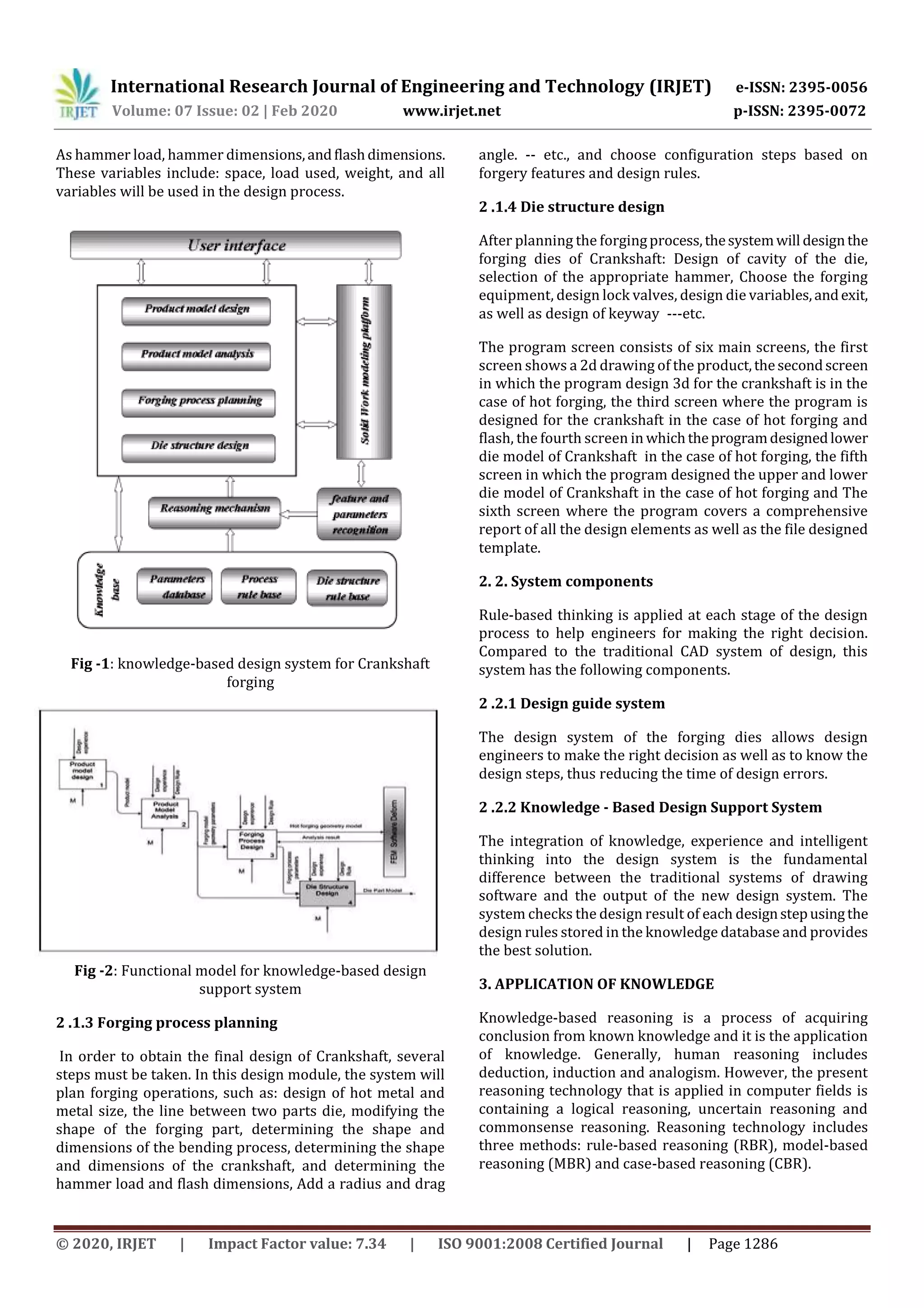
diagram, this is illustrated in Fig.1.
2.1 System structure and main functional modules
The system is composed of four subsystems: product model
design, product model analysis, forging process planning,
and die structure design. These subsystems are interrelated
based on the integrated product model. This is illustrated in
Fig.2.
2.1.1 Product model design
The three-dimensional shape of Crankshaft is designed by
using the Solid Works software.
2 .1.2 Product model analysis
Based on Crankshaft design that was created, analyze
drawing elements from Solid Works,establishingknowledge
bases such](https://image.slidesharecdn.com/irjet-v7i2267-201118041136/75/IRJET-Knowledge-based-Forging-Die-Design-of-Crankshaft-1-2048.jpg)
![International Research Journal of Engineering and Technology (IRJET) e-ISSN: 2395-0056
Volume: 07 Issue: 02 | Feb 2020 www.irjet.net p-ISSN: 2395-0072
© 2020, IRJET | Impact Factor value: 7.34 | ISO 9001:2008 Certified Journal | Page 1287
In the process of forging die design, RBR is the primary
reasoning technology to provide proper knowledge. In the
forging die design, there are several designrules.Theserules
are saved in the rule database of the system by way of the
production rule. While designing, rule-based reasoning is
applied according to specific conditions. Producingrulesare
put forward by US mathematician Post, and developed by
Newell and Simon. Producing representation is also called
rules representation. Each rule is a producing expression.
Every rule contains two parts, one is situation of recognition
(premise/antecedent part), and the other is the activitypart
(conclusion/consequent part). Producing rules werelooked
at the situation-activity pairs or premise-conclusion pairs.
Base Production Production rule is similar to logic in form:
P→ Q, CF. In this formula: P is antecedent, Q is consequent,
and CF is the certainty factor of the rule. The following is the
BNF description of producing rules using the logical
knowledge representation method:
< Predication >::=< Name of predication>[< Parameter >,...]
< Action >::=< Name of action >[< Parameter >,...]
<Premise>::=empty| < Predication >1, < Predication >|
<Conclusion>::=< Predication >| < Action >{ Conclusion...}
< Production rule >::=< Premise >< Conclusion >,<CF>
<CF>::=<(0,1)real number>
< Production knowledge>::=< Production rule >1,
< Production rule >2,...
For example, during system design the capacity of hammer
(H) can be selected according to average diameter of
workpiece (D) of the metal used and can be determined
according to Table 1 .
H =10 (1- 0.005*D) (1.1+2/D)² (0.75+0.001D²)*D*ƿ (1)
Table -1: The relationship between the capacity of
hammer (H) and average diameter of workpiece (D) [12].
The design rules:
IF D <=4.5 THEN H= 0.63
IF D >4.5 AND D <=8.5 THEN H=1
IF D >8, 5 AND D <=17 THEN H=2
IF D >17 AND D <=20 THEN H=2.5
IF D >20 AND D <=24 THEN H=3.15
IF D >24 AND D <=31 THEN H=5
IF D>31 AND D<=44 THEN H=10
For example, during system design of Dimensions of the
flash (F) can be selected accordingto thecapacityofhammer
(H) of the metal used and can be determined according to
Table 2
The design rules:
IF F1 THEN H=0.63
IF F2 THEN H=1
IF F3 THEN H=2
IF F4 THEN H=2.5
IF F5 THEN H=3.15
IF F6 THEN H=5
IF F7THEN H=10
Table -2: The relationship between the capacity of
hammer (H) and the flash (F) [12].
For example, during system design of Dimensions of the
hammer (Dh) can be selected according to the capacity of
hammer (H) of the metal used and can be determined
according to Table 3.
Table -3: The relationship between the capacity of
hammer (H) and Dimensions of the hammer(Dh) [12].
The design rules:
IF Dh1 THEN H=0.63
IF Dh2 THEN H=1
D (cm)
> 4.5 4.5 ≤
8.5
8.5 ≤
17
17 ≤
20
20 ≤
24
24 ≤
31
31 ≤
44
H( ton) 0.63 1 2 2.5 3.15 5 10
H
( ton)
F
(mm)
A R2 h R R1 L L1
0.63 F1 0.5 0.5 4 4 1 8 25
1 F2 0.8 0.8 4 4 1.5 8 30
2 F3 1.5 1.5 4 4 1.5 10 35
2.5 F4 1.5 1.5 5 5 1.5 10 35
3.15 F5 1.5 1.5 5 5 1.5 10 35
5 F6 2 2 6 6 3 12 40
10 F7 2.5 2.5 8 8 3 12 50
H ( ton) Dh)mm) H min H max B L
0.63 Dh1 280 380 400 380
1 Dh2 320 500 500 450
2 Dh3 360 550 600 700
2.5 Dh4 430 650 700 710
3.15 Dh5 480 650 700 800
5 Dh6 530 800 700 1000
10 Dh7 610 810 1000 1200](https://image.slidesharecdn.com/irjet-v7i2267-201118041136/75/IRJET-Knowledge-based-Forging-Die-Design-of-Crankshaft-3-2048.jpg)
![International Research Journal of Engineering and Technology (IRJET) e-ISSN: 2395-0056
Volume: 07 Issue: 02 | Feb 2020 www.irjet.net p-ISSN: 2395-0072
© 2020, IRJET | Impact Factor value: 7.34 | ISO 9001:2008 Certified Journal | Page 1289
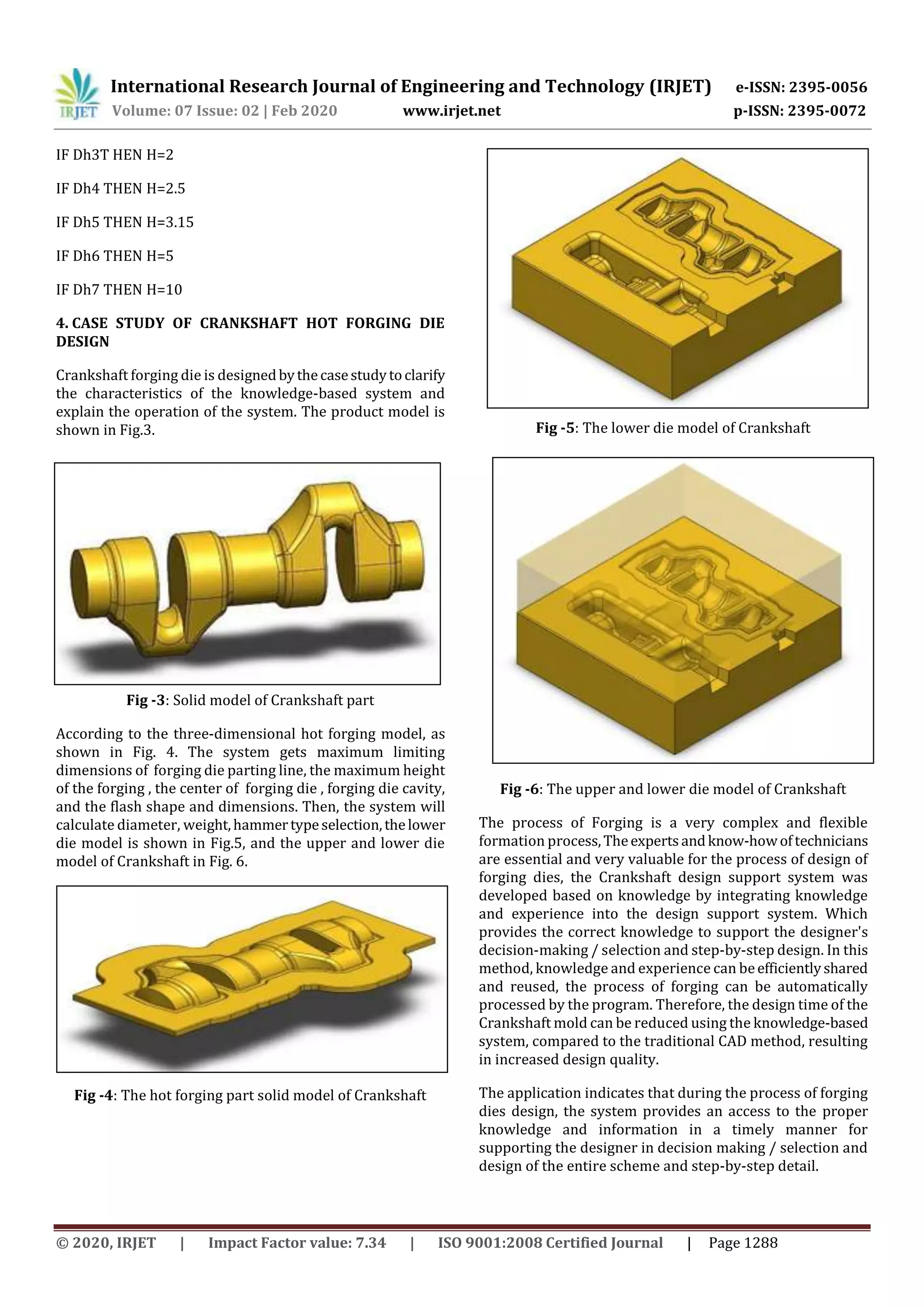
5. CONCLUSIONS
During forging dies design process, the accumulated
experience and knowledge of designers is very important.
For the design of die. In order to optimize the accumulated
engineering knowledge, it is necessary to integrate
knowledge and experience in designingforgingdiessystems
into a CAD system and developinga knowledge-baseddesign
support system. In this work, a knowledge-basedCrankshaft
design support system has been developed on the basis of
methodology. Through the representation of engineering
knowledge, knowledge acquisition and knowledge-based
design support techniques. A case study shows in this work
by adopting this system the following:
1. Using the automatic design instead of manual
design
2. The product development cost reduced
3. To save time and effort greatly
4. To reduce errors caused by designers
5. Improvement the quality of the design
NOMENCLATURE
SUBSCRIPTS
CAD Computer Aided Design
CAM Computer-Aided Manufacturing
CAE Computer-Aided Engineering
CADD Computer Aided Design And Drafting
RBR Rule-Based Reasoning
MBR Model-Based Reasoning
CBR Case-Based Reasoning
REFERENCES
[1] Numthong C.Butdee S. "The Knowledge Based System
for Forging Process Design based on Case-Based
Reasoning and Finite Element Method" AIJSTPME,
2012, 5(2): 45-54
[2] F. Diko, M.S.J. Hashmi," A finite element simulation of
non steady state metal forming processes" J. Mater.
Process. Technol. 38 (1993) 115–122.
[3] M.S. Joun, S.M. Hwang "Optimal process design in
steady-state metal forming by finiteelementmethod"
II. Application to die profile design in extrusion, Int. J.
Mech. Tools Manuf. 33 (1) (1993) 63–70
[4] M. Knoerr, L. Joon, A. Taylan, Application of the 2D
finite element methodtosimulationofvariousforming
processes, Journal of materials processing technology
33(1-2),31-55,1992.
[5] Mantyla M, Nau D, Shah J. "Challenges in feature-based
manufacturing research" Communications of theACM
1996;39(2):77–85
[6] Y.K.D.V. Prasad and S. Somasundaram, "CADDS An
Automated Die Design System for Sheet Metal
Blanking.", Computing and Control Engineering
Journal, V.3, n.4, pp.185-191, , July 1992.
[7] Choi S. H. And Wong K.W.,"A CAD/CAM package for
sheet metal blanking dies.", In the proceedings of the
International Conference of Manufacturing
Automation"Hong Kong(10-12August1992),pp.674-
679,1992.
[8] H.S. Ismail, K. Huang and K.k.B .Hon, "CAPTD: a low-
cost integrated computer aided design system for
press-tool design," I-Mech-E, Part B, Journal of
Engineering Manufacture vol. 207 n B2, pp. 117-127,
1993.
[9] R. Singh and G. S. Sekhon," Design and Application of
Hybrid SoftwareforModelingDieComponentsandDie
Assembly", I-Mech-E, Part B: Journal of Engineering
Manufacture, vol. 217, pp. 235-250, 2003.
[10] Hussein H.M.A., Abdeltif, L.A.,Etman,M.I.,andBarakat
A. F., "An Approach to Construct an Intelligent System
in Sheet Metal Cutting Die Design"., 9th Cairo
university international conference on mechanical
design & production (MDP-9) Cairo, Egypt, January 8-
10, 2008.
[11] Xiong N, Litz L, Ressom H "Learning premises of fuzzy
rulesfor knowledge acquisition in classification
problems." Knowl Inf Syst4(1):96–111, 2002
[12] Abdelnaser Omran "ComputerAidedProcessPlanning
and Design of Forging Dies" PhD under progress,
Faculty of Industrial Education, Helwan University,
Cairo, Egypt, 2020.
Symbol Description Unit
H The capacity of hammer ton
ƿ Density Kg / cm3
D Diameter cm
F Dimensions of the flash mm
Dh Dimensions of the hammer mm
H min Maximum Height mm
H max Minimum Height mm
B Die Width mm
L Dei Length mm](https://image.slidesharecdn.com/irjet-v7i2267-201118041136/75/IRJET-Knowledge-based-Forging-Die-Design-of-Crankshaft-5-2048.jpg)


The document describes a knowledge-based system for designing forging dies for crankshafts. The system uses knowledge bases containing relationships between design parameters like hammer load, dimensions, and flash size. It integrates CAD software to design the crankshaft and die models. Rules are applied at each design stage to help engineers make decisions. The system was tested on a crankshaft die design case study and showed benefits like reduced time/errors and improved quality compared to traditional CAD methods.