Downloaded 23 times
![(a) Illustration of the operating principle of a Mg–Na
hybrid battery. During battery discharging, Na+ ions
intercalate into the cathode and Mg2+ ions dissolve
from a Mg anode. The corresponding voltage
profiles of the positive and negative electrodes are
shown in orange and blue lines, respectively.
(b) Electro-active species involved during charging a
hybrid battery made of a Na3V2(PO4)3 cathode, a Mg
anode, and an electrolyte of 0.2 M [Mg2Cl2][AlCl4]2
and 0.4 M NaAlCl4 in DME
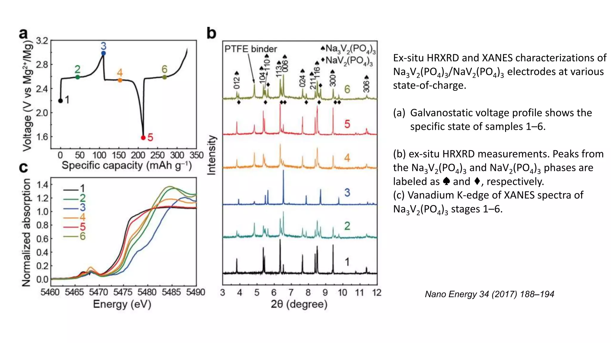
A high-voltage rechargeable magnesium-sodium hybrid battery
Nano Energy 34 (2017) 188–194](https://image.slidesharecdn.com/mgib-171220090136/75/Mg-ib-3-2048.jpg)

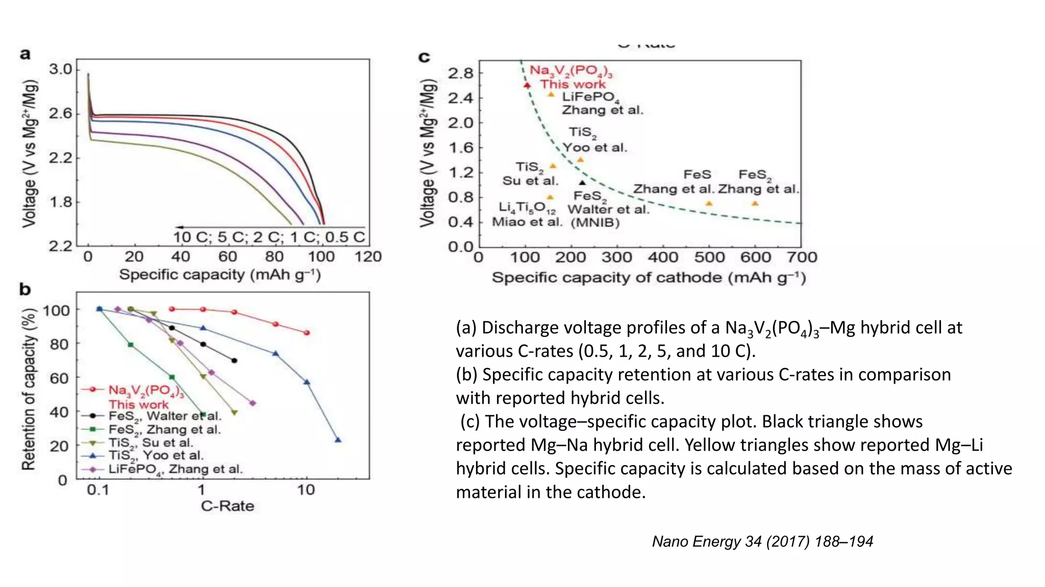


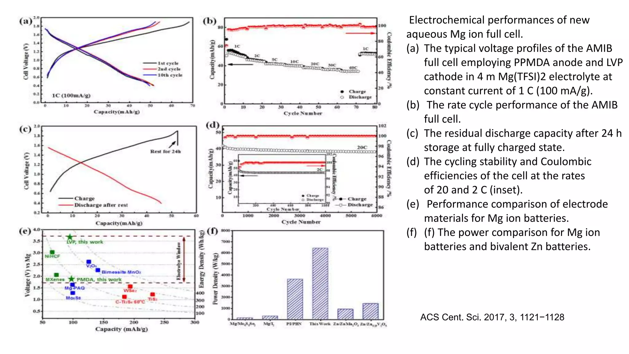


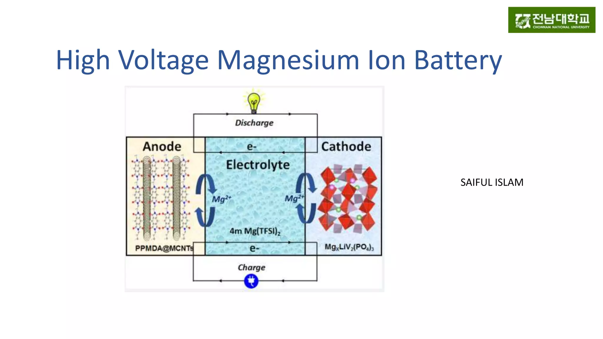
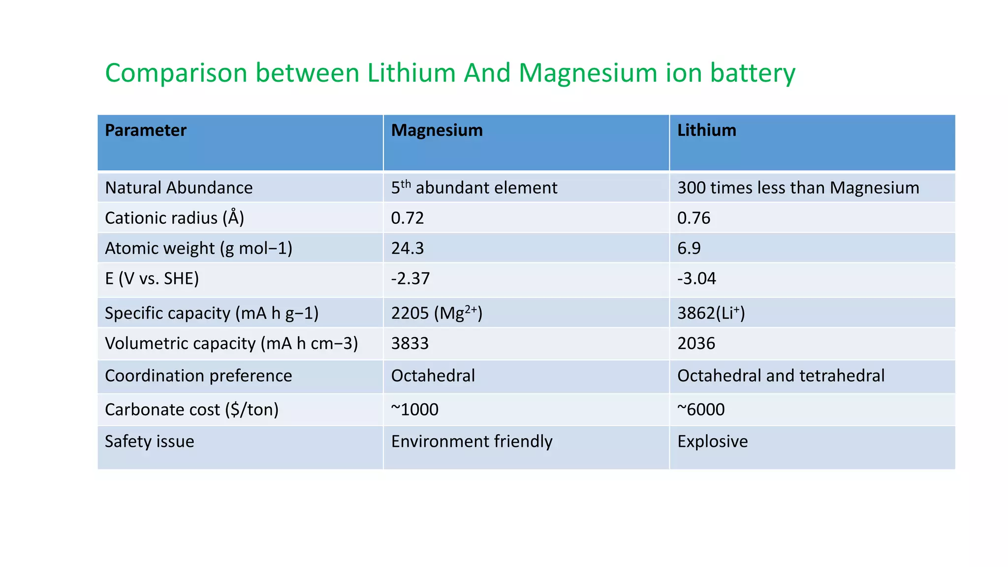
1) Magnesium ion batteries have several advantages over lithium ion batteries including higher natural abundance, lower cost, and greater safety. 2) This document describes a high-voltage magnesium-sodium hybrid battery using a Na3V2(PO4)3 cathode and magnesium anode that achieves a voltage of 3.5 V and capacity retention of 80% over 50 cycles. 3) It also presents a new design for an aqueous magnesium ion battery using a LiVP cathode and PPMDA anode that achieves high voltage of 3 V and capacity retention of 80% over 100 cycles.


