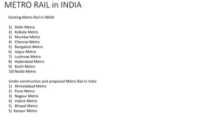
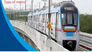
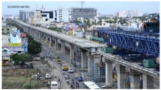
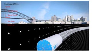
Metro rail systems were introduced in India to address issues of unprecedented growth in personal vehicles, traffic congestion, air pollution, and accidents. India's first metro was constructed in Kolkata in 1984, while Delhi Metro began operating in 2002. There are now metros operating in many major Indian cities, with several more under construction to improve urban transport infrastructure. The document discusses the different types of metro rail systems used in India including elevated, underground, and at-grade systems as well as methods for their construction.
The document provides information on various aspects of metro projects, including common terminology used, the different types of metro systems (elevated, underground, on grade), and construction methods. It discusses features of elevated and underground metros such as viaducts, stations, tunnels, and cut-and-cover construction. Diagrams and photos show the construction process for elevated viaducts using different methods as well as underground metros using cut-and-cover and top-down construction approaches.
Construction sequence for metro Project (Elevated and Underground) and Time c...Akhilesh Shukla
Construction sequence for metro Project (Elevated and Underground) and Time cycle of the metro construction activity . For more details u can contact me on my mail id -shuklaakhilesh08@gmail.com
When evaluating mass transit options for Indian cities, metro rail systems are given preference over surface systems due to the belief that road-based bus systems cannot cater to the capacity requirement as much as metro systems can. In addition, metro rails are perceived to have higher levels of comfort, speed, and efficiency than bus systems.
This document provides an overview of various types of construction equipment, including their classification and uses. It discusses earth moving equipment such as power shovels, backhoes, draglines, and clam shells. It also covers compacting equipment like smooth wheel rollers, sheep-foot rollers, and pneumatic tired rollers. Additional equipment covered include pile driving rigs and their uses in transferring surface loads into the ground. The document aims to classify and explain the purpose and functioning of many important pieces of machinery used in construction projects.
The document provides an overview of depot design and construction for Riyadh Metro. It discusses the various depot types including main depots, secondary depots, and stabling facilities. It describes the functions of key buildings within the depots like workshop buildings, administration buildings, and vehicle wash buildings. The document outlines the design process including developing requirements, producing design outputs, and using BIM modeling. It then discusses the construction phase including execution strategies, early works, civil works, steel erection, and finishing works. In summary, the document covers both the design and construction of the various depot facilities needed to support operations for Riyadh Metro.
The document summarizes key details about Phase 1 of the Jaipur Metro project. Phase 1 will include two corridors from Sitapura to Ambabadi running north-south and from Mansarovar to Badi Chaupar running east-west, totaling nearly 30 kilometers at an estimated cost of Rs. 8,000 crores. Construction will use concrete grades between M-35 to M-55 and involve techniques like pile foundations, precast girders and slabs, and safety measures for workers and the public. The metro aims to reduce traffic and travel times in rapidly growing Jaipur city.
INDUSTRIAL TRAINING OF FLYOVER CONSTRUCTIONBhavek Sharma
The Public Works Department has a long history of infrastructure development in the state. It is responsible for constructing and maintaining roads, bridges, and government buildings. Originally, irrigation and public health engineering were also part of the PWD. Since its inception, the department has strived for excellence through continuous improvement and engineering milestones.
This document is a project report submitted in partial fulfillment of a Bachelor of Technology degree in Civil Engineering. It examines the design and estimation of an RCC (reinforced cement concrete) road. The report was submitted by seven students to their lecturer at Indus Institute of Technology and Management in Kanpur, Uttar Pradesh, India in May 2015. It includes sections on surveying, road specifications, field surveys, analysis of rates, design, estimation, and costing of the RCC road project.
Urban transportation system meaning ,travel demand functions with factors, design approaches & modeling , types of mass transit system with advantages -disadvantages or limitations , opportunities in mass transport , integrated approach for transit -transportation system
The document discusses the architecture and development of the Hyderabad metro rail system. It provides details about:
1) The Indo-French architectural influences on the metro station designs that blend historical styles with modern development.
2) Key facts about the three metro corridors covering over 71 km and 2748 piers supporting the rail lines.
3) The Nagole metro station specifically, located near a train depot and cash and carry along a busy road, and its cantilevered design mounted on a central pillar to accommodate heavy traffic flow in the area.
This is a powerpoint presentation on summer training from public works department. This presentation will be very helpful for civil engineering students.
Segmental bridge construction involves building bridges out of precast concrete segments. This allows for longer spans than traditional methods by reducing the need for intermediate piers. There are several techniques for segmental bridge construction including cast-in-place using form travelers, incremental launching where segments are cast and then pushed out over supports, and precast segment erection using launching girders. Segmental construction enables building bridges more quickly and over existing infrastructure with minimal traffic disruptions.
The Hyderabad Metro Rail Project is a case study of a new metro network being constructed in Hyderabad, India. The 72 km metro network consists of three color-coded corridors and will cost Rs. 14,320 crore to construct. L&T Metro Rail Hyderabad Limited is responsible for most of the project costs. The metro will use 57 three-car train sets able to travel at up to 90 km/h, controlled by an automatic train operation system. Station designs reflect local culture and provide covered access between platforms and exits. The metro aims to reduce travel times and traffic congestion compared to road-based transportation in Hyderabad.
The document provides details about the construction of the CC-27 metro corridor project in Delhi. It discusses the proposed route, construction methods used at different stations, specifications of materials like concrete mixes, and repair works. The bottom-up construction approach is used at Vasant Vihar due to hard rock, while soft soil at Hauz Khas uses a top-down method. Waterproofing involves applying a two-component polyurethane coating after priming and adding aggregates to the primer layer.
Railway secondary part of the transportation . Railway use of maximum materials transport of one place to other place. Particular time of number of trains are move of particular junction so these part are used of points and crossing.
Best helpful of these ppt of railway track and design purposes.
1. The document discusses the history and development of metro rail systems across several major cities in India, including Kolkata, Delhi, Mumbai, Bangalore, Hyderabad, Chennai, and Kochi.
2. It provides details on the operational characteristics, routes, costs, and ridership numbers for the existing and proposed metro systems.
3. Benefits of metro rail over other public transportation options include reduced energy usage, pollution, traffic congestion, and travel times, as well as increased passenger capacity and cost effectiveness.
India's first metro rail system was introduced in Kolkata in 1984 to address issues of traffic congestion and pollution from growing vehicle ownership. Metro systems now exist or are planned for many major Indian cities, including Delhi, Mumbai, Bangalore, Hyderabad, and Chennai. These systems aim to shift travelers from private vehicles to more efficient public transit in order to handle rapid urbanization and population growth. While metro projects require huge initial investments, they provide environmental and transportation benefits by reducing energy use, emissions, road congestion, and travel times compared to private vehicles.
PRESENTATION ON ROAD CONSTRUCTION INTERNSHIP NH34 BY IMRUL QUESHImrul Quesh
This document provides an overview of road construction and quality control processes. It discusses the importance of roads for transportation and economic development. It then describes the planning process for road projects, including maintaining files, analyzing labor and equipment needs, and preparing plans. The document outlines different types of road structures, quality control procedures and tests, and safety measures for road works. Machinery used on road construction sites is also listed. Overall, the document covers key aspects of road construction projects from planning and design to quality assurance and safety.
Prestressed concrete has several advantages over reinforced concrete including being more crack-resistant, durable, and requiring smaller cross-sectional areas, allowing for longer spans and easier transport. However, it also has some disadvantages such as requiring specialized equipment, advanced technical knowledge, and skilled labor for construction, as well as more expensive prestressing reinforcement bars.
This document discusses the design of an underpass. It begins with objectives such as reducing accidents and providing safe and hassle-free movement of vehicles and pedestrians. It describes the methodology, survey results of the existing junction, traffic count data, soil testing results, and design of the road, box culvert, and overbridge. It includes analysis of loads and moments on structural elements. Reinforcement details are provided. Cost estimation and conclusions that the underpass will maintain vehicle speed and reduce accidents are also summarized.
This document discusses several key aspects of metro rail station planning and design, including:
1. Types of metro stations such as underground, on-grade, and elevated, as well as center and side platforms.
2. Design criteria for metro stations including passenger capacity, accessibility, construction feasibility, and life safety measures.
3. Coordination challenges between different disciplines during design and construction. International standards like NFPA 130 provide guidelines for fire protection and evacuation.
4. Interchange stations require special wayfinding signage due to their complex layouts with transfers between lines.
This document provides details on the design of multi-level station piers for elevated metro corridors. It describes the main components of the station pier, including the main pier, pier above the concourse arm, and pier above the pier cap. It discusses the forces acting on the piers, including axial, shear, moment, and torsion forces. It also provides details on the geometric dimensions, cable profiling, reinforcement, and design considerations for the piers.
A paver is a piece of construction equipment that lays asphalt flat and provides minor compaction before a roller compacts it fully. There are different types of pavers including asphalt crawler pavers, asphalt wheeled pavers, and concrete pavers, which can operate on wheels or tracks depending on the pavement surface. Pavers are used to lay asphalt on roads, highways, ports, parking lots, and other areas.
The document discusses different types of roads in India and their geometric design elements. It provides details on calculating the pavement thickness for water bound macadam roads based on traffic volume data and soil strength. The summary construction involves spreading aggregates in layers, rolling, adding screenings, sprinkling water and binding material to fill voids, and allowing it to dry before further construction. Proper drainage is emphasized to prevent water damage to the road pavement.
This document provides an overview of the Transportation Engineering II course syllabus and discusses various topics that will be covered, including railway geometric design, station and yard design, airport engineering, and harbor and dock engineering. It also summarizes key concepts related to permanent way design, including subgrade, formation, embankment, track drainage, rails, rail fastenings, sleepers, and ballast. Modern trends in rail such as MAGLEV, tube, and metro rail systems are also introduced.
The document provides information about an industrial training report submitted by MD. Shadab for their Bachelor of Technology degree in Civil Engineering. It includes details about the company J. Kumar & CRTG Joint Venture where the training took place, working on the Delhi Metro Rail Project Phase-III underground construction. Key points:
(a) The report describes MD. Shadab's industrial training working on the Delhi Metro Rail Project Phase-III underground construction from July 10th to August 10th 2017 under the supervision of J. Kumar & CRTG Joint Venture.
(b) It includes details about the companies involved in the project like J. Kumar, CRTG, and DMRC, as well
This document provides a summary of a tool box talk on dry end safety at a paper mill. The talk covers:
1. Reel crane safety inspections that are required by OSHA at the start of each shift.
2. Proper procedures for reel turn-ups and parking cranes to avoid accidents like reels falling or getting stuck.
3. The importance of focusing on equipment operation and avoiding distractions to prevent injuries from machinery.
4. An update on procedures for operating the core cutter.
The document reviews safety requirements and procedures to minimize dry end risks and comply with regulations.
1. The document describes a 360 degree rotated gearbox trolley that can unload cargo in congested areas by rotating the trolley 360 degrees about its center using a worm and worm wheel mechanism.
2. A lead screw and universal joint allow the trolley to lift at any angle, providing flexibility for unloading. The modern alternative is a hydraulic system, but this design uses the lead screw for lifting.
3. The key components are the worm and worm gear for rotation, a lead screw, universal joint, and toggle jack for lifting. It was designed and tested to be more effective for unloading than commonly used methods.
The document give a brief idea of geneva mechanism and how it operates. this document also gives procedure to make geneva mechanism, methodology, components, design and calculations
Waste disposal system of railway wagonRajeshvaliya
1. The document proposes a waste disposal system for railway wagons that collects toilet waste in tanks and automatically discharges it at designated locations along the tracks equipped with the disposal system.
2. The key components of the system include waste collection tanks in each wagon, a mechanism attached to the tank that opens a valve when passing over a sloped section of track, and a drainage path to direct waste to biogas digesters.
3. Detailed calculations are provided for the tank dimensions, valve operation mechanism including the pinion gear, timing of waste discharge, and spring design for the opening/closing mechanism. The system aims to improve railway station sanitation in an affordable manner.
INDUSTRIAL SUMMER TRAINING (IST)
Introduction
Layout of Tbea energy (india) pvt ltd
Basics of transformer
Information flow diagram
Transformer manufacturing process
Testing of transformer
Main Unit & Trailer Packing Check
Dispatch
Conclusion
Development Of Tipper Unloading MechanismIRJET Journal
1. The document describes the development of a tipper unloading mechanism to allow a tipper truck to unload material in multiple directions rather than just the rear.
2. Currently, tipper trucks can only unload material out the back, which reduces efficiency when precise unloading locations are required. It also requires the truck be parked in certain positions.
3. The proposed design involves adding two additional hydraulic cylinders on the sides of the tipper bed, allowing material to be unloaded to the left or right as well as the rear. This would provide more flexibility in unloading location without repositioning the truck.
4. Calculations are provided for the existing rear unloading mechanism involving the hydraulic cylinder, motor,
Mitsubishi Electric is a global leader in elevator and escalator technology. It has 11 overseas manufacturing plants and delivers products to over 90 countries worldwide. Mitsubishi aims to maintain the same high quality standards across its operations through original technology, strict design and branding, and sourcing of core parts from its main factory in Japan. Key facilities include the mother factory in Inazawa, Japan and a large production plant in Thailand that supplies elevators and escalators across Asia. Mitsubishi's commitment to quality and innovation has led to its position as the top-rated elevator brand in many countries and markets.
This document provides a final report on the conceptual design, calculations, and justification of a skidded helicopter tug. It includes sections on problem definition, project brief, conceptual design selection, and detailed design calculations. The calculations cover topics such as load calculations on the scissor jack and lead screw, gear and shaft dimensions, bearing selection, and energy losses. The conceptual design process evaluated three concepts and selected a design using a scissor jack, electric motor, remote control, and sliding mesh gearbox. The detailed calculations size components and check that stresses will be below allowable values when lifting the maximum load of 3500kg.
This document provides a summary of the vocational training report of Prashant Kumar Patel at SECR Railway Bilaspur during 2017-18. It includes summaries of his time spent at the Major Sick Line learning repair work such as door repairing and wheel changing. It also summarizes his time at the BCN Depot learning about overhaul work including the machines used. Finally, it summarizes his time at the Coaching Depot learning about the maintenance and overhaul work performed on coaches.
This document discusses procedures for tripping out pipes during drilling operations. It begins with introductions to drilling rigs and definitions of tripping out as the process of removing drill pipe sections. The objectives are then stated as removing worn or broken pipes for replacement or installing a bottom hole assembly. Equipment used in tripping out like the drawworks, drill pipe, slips, and iron roughneck are described. Step-by-step procedures for tripping out are outlined, including using the drawworks to hoist and lower the drill string, opening and closing slips, detaching joints with the iron roughneck, and storing pipes in the rathole or rack. The conclusion emphasizes that tripping out must be done carefully to
This document provides a summary of the walkway construction project from 2014-2016 for CTCI Singapore & CTCI Corporation Consortium. It describes the organization structure, components and methods of construction. Key aspects included base infill, support unit casting, cable trough installation, ramp construction, and handover requirements. Construction efficiency, manpower, tools/equipment, drawings and conclusions/lessons learned are also summarized. Proper planning and coordination between teams was important to the successful and timely completion of the 28km of walkway construction.
Design and Fabrication of Multi Speed Centrifugal PumpRaushan Sah
This document summarizes a student project to design and fabricate a multi-speed centrifugal pump. The project uses a cone-shaped pulley connected to the pump by a round belt to allow variable pump speeds by moving the belt to different positions on the pulley. Calculations are shown to determine pump discharge rates at different belt/pulley configurations. The design is intended to provide a low-cost way to vary pump discharge rates for various industrial and agricultural applications. Future enhancements could include automation and improved components for longer operation.
inclined car parking lift mechanism system by 070 batch (IOE Pulchowk)Dinesh Rawal
The document describes the design, fabrication and testing of an inclined car parking lift mechanism. It includes sections on the objectives, literature review, methodology, design calculations, components, working principle, results and analysis, costing, and conclusions. The key points are:
1. The project aims to design a vehicle lifting mechanism for easy movement on an inclined surface and analyze its operating cost.
2. A review of literature on lift systems from 1929 to present day showed they are powered by electric motors or hydraulic pumps to efficiently park vehicles.
3. The methodology involved concept development, data collection, design, fabrication, testing, and analysis of stress, velocity and operating costs with varying payloads.
4.
Introduced gearless power transmission arrangement used for skew shafts. In this transmission system no. of pins or links used must be odd..3,5,7,9…..& centers of any two pins or links hole must not be on that line which represent the diameter of the shaft. If more pins or links used motion will be smoother, but increase in no. of pins or links not at the cost of strength of the shaft. Pins or links are fixed (may be permanent of temporary) in the drilled holes at the both shaft ends due to which motion is transferred. The dimensions of the pins or links and angle for the pins are all given very precisely, holes drilled very accurately.
Proposed arrangement used for skew shafts at any angle & if there is a need we can change the angle between shafts during motion or during intermittent motion with any profile of shafts having rotational motion along its own axis. The Working of this arrangement is very smooth & use very effectively with a very minimum amount of power losses.
The document discusses the use of lifting frames and anchors for installing prefabricated pre-finished volumetric construction (PPVC) modules. It covers the purposes of the lifting frame, assembly and planning considerations, design aspects for safety, and challenges on-site. The lifting frame is designed to safely transfer loads from the PPVC module during lifting and positioning. Anchor locations are planned based on module center of gravity to prevent structural failures. Safety is a primary concern in the lifting frame and anchor design.
1) The document is a summary of a webinar about engineered pipe supports provided by Piping Technology & Products, Inc (PT&P).
2) It discusses different types of variable and constant spring supports, how to size, select, install, and maintain them.
3) The webinar provides guidance on inspection criteria and procedures for repairs, replacements, and isolating pipe systems during maintenance.
The document provides information on propping equipment available from Coates Hire, including Acrow props, Strong Boy wall supports, Titan super props, Titan ledger frames and accessories, Mini Tri props, and Trishore props. It details the specifications, load capacities, and applications of each type of propping equipment. Coates Hire offers expertise in propping solutions and can assist with engineering design and technical support for projects.
CIVIL CONSTRUCTION INFATIMA FERTILIZER COMPANY LIMITEDWater Birds (Ali)
This document provides an overview of the civil construction and structures at Fatima Fertilizer's plant. It discusses the project overview including key features and timelines. It then describes the civil engineer's role in establishing projects like Fatima Fertilizer which includes various complex structures from foundations to buildings. It highlights the use of steel and concrete frame structures. The document also outlines the author's work areas including roads, a weigh bridge, and the Nitro Phosphate plant. It provides details on constructing roads using rigid pavement and the weigh bridge. For the NP plant, it discusses the prilling tower construction using slip forming and strengthening of columns.
DESIGN OF MINE SHAFT ELEVATOR design guideSuresh Ramarao
This document discusses the design of a mine shaft elevator. It begins by providing background on the history and types of elevators. It then describes design considerations for mine shaft elevators, including options for shaft design (circular vs. horizontal) and parameters like speed, motor selection, suspension ropes, and guide rails. Calculations are shown for selecting these components for a case study mine shaft elevator with a lifting capacity of 32 tons and a height of 730 meters. Key parameters of the elevator design are presented in a table. The conclusions compare the computer-calculated design values to standard parameters.
Abhay Bhutada Leads Poonawalla Fincorp To Record Low NPA And Unprecedented Gr...Vighnesh Shashtri
Under the leadership of Abhay Bhutada, Poonawalla Fincorp has achieved record-low Non-Performing Assets (NPA) and witnessed unprecedented growth. Bhutada's strategic vision and effective management have significantly enhanced the company's financial health, showcasing a robust performance in the financial sector. This achievement underscores the company's resilience and ability to thrive in a competitive market, setting a new benchmark for operational excellence in the industry.
Financial Assets: Debit vs Equity Securities.pptxWrito-Finance
financial assets represent claim for future benefit or cash. Financial assets are formed by establishing contracts between participants. These financial assets are used for collection of huge amounts of money for business purposes.
Two major Types: Debt Securities and Equity Securities.
Debt Securities are Also known as fixed-income securities or instruments. The type of assets is formed by establishing contracts between investor and issuer of the asset.
• The first type of Debit securities is BONDS. Bonds are issued by corporations and government (both local and national government).
• The second important type of Debit security is NOTES. Apart from similarities associated with notes and bonds, notes have shorter term maturity.
• The 3rd important type of Debit security is TRESURY BILLS. These securities have short-term ranging from three months, six months, and one year. Issuer of such securities are governments.
• Above discussed debit securities are mostly issued by governments and corporations. CERTIFICATE OF DEPOSITS CDs are issued by Banks and Financial Institutions. Risk factor associated with CDs gets reduced when issued by reputable institutions or Banks.
Following are the risk attached with debt securities: Credit risk, interest rate risk and currency risk
There are no fixed maturity dates in such securities, and asset’s value is determined by company’s performance. There are two major types of equity securities: common stock and preferred stock.
Common Stock: These are simple equity securities and bear no complexities which the preferred stock bears. Holders of such securities or instrument have the voting rights when it comes to select the company’s board of director or the business decisions to be made.
Preferred Stock: Preferred stocks are sometime referred to as hybrid securities, because it contains elements of both debit security and equity security. Preferred stock confers ownership rights to security holder that is why it is equity instrument
<a href="https://www.writofinance.com/equity-securities-features-types-risk/" >Equity securities </a> as a whole is used for capital funding for companies. Companies have multiple expenses to cover. Potential growth of company is required in competitive market. So, these securities are used for capital generation, and then uses it for company’s growth.
Concluding remarks
Both are employed in business. Businesses are often established through debit securities, then what is the need for equity securities. Companies have to cover multiple expenses and expansion of business. They can also use equity instruments for repayment of debits. So, there are multiple uses for securities. As an investor, you need tools for analysis. Investment decisions are made by carefully analyzing the market. For better analysis of the stock market, investors often employ financial analysis of companies.
BONKMILLON Unleashes Its Bonkers Potential on Solana.pdfcoingabbar
Introducing BONKMILLON - The Most Bonkers Meme Coin Yet
Let's be real for a second – the world of meme coins can feel like a bit of a circus at times. Every other day, there's a new token promising to take you "to the moon" or offering some groundbreaking utility that'll change the game forever. But how many of them actually deliver on that hype?
2. Elemental Economics - Mineral demand.pdfNeal Brewster
After this second you should be able to: Explain the main determinants of demand for any mineral product, and their relative importance; recognise and explain how demand for any product is likely to change with economic activity; recognise and explain the roles of technology and relative prices in influencing demand; be able to explain the differences between the rates of growth of demand for different products.
^%$Zone1:+971)581248768’][* Legit & Safe #Abortion #Pills #For #Sale In #Duba...mayaclinic18
Whatsapp (+971581248768) Buy Abortion Pills In Dubai/ Qatar/Kuwait/Doha/Abu Dhabi/Alain/RAK City/Satwa/Al Ain/Abortion Pills For Sale In Qatar, Doha. Abu az Zuluf. Abu Thaylah. Ad Dawhah al Jadidah. Al Arish, Al Bida ash Sharqiyah, Al Ghanim, Al Ghuwariyah, Qatari, Abu Dhabi, Dubai.. WHATSAPP +971)581248768 Abortion Pills / Cytotec Tablets Available in Dubai, Sharjah, Abudhabi, Ajman, Alain, Fujeira, Ras Al Khaima, Umm Al Quwain., UAE, buy cytotec in Dubai– Where I can buy abortion pills in Dubai,+971582071918where I can buy abortion pills in Abudhabi +971)581248768 , where I can buy abortion pills in Sharjah,+97158207191 8where I can buy abortion pills in Ajman, +971)581248768 where I can buy abortion pills in Umm al Quwain +971)581248768 , where I can buy abortion pills in Fujairah +971)581248768 , where I can buy abortion pills in Ras al Khaimah +971)581248768 , where I can buy abortion pills in Alain+971)581248768 , where I can buy abortion pills in UAE +971)581248768 we are providing cytotec 200mg abortion pill in dubai, uae.Medication abortion offers an alternative to Surgical Abortion for women in the early weeks of pregnancy. Zone1:+971)581248768’][* Legit & Safe #Abortion #Pills #For #Sale In #Dubai Abu Dhabi Sharjah Deira Ajman Fujairah Ras Al Khaimah%^^%$Zone1:+971)581248768’][* Legit & Safe #Abortion #Pills #For #Sale In #Dubai Abu Dhabi Sharjah Deira Ajman Fujairah Ras Al Khaimah%^^%$Zone1:+971)581248768’][* Legit & Safe #Abortion #Pills #For #Sale In #Dubai Abu Dhabi Sharjah Deira Ajman Fujairah Ras Al Khaimah%^^%$Zone1:+971)581248768’][* Legit & Safe #Abortion #Pills #For #Sale In #Dubai Abu Dhabi Sharjah Deira Ajman Fujairah Ras Al Khaimah%^^%$Zone1:+971)581248768’][* Legit & Safe #Abortion #Pills #For #Sale In #Dubai Abu Dhabi Sharjah Deira Ajman Fujairah Ras Al Khaimah%^^%$Zone1:+971)581248768’][* Legit & Safe #Abortion #Pills #For #Sale In #Dubai Abu Dhabi Sharjah Deira Ajman Fujairah Ras Al Khaimah%^^%$Zone1:+971)581248768’][* Legit & Safe #Abortion #Pills #For #Sale In #Dubai Abu Dhabi Sharjah Deira Ajman Fujairah Ras Al Khaimah%^^%$Zone1:+971)581248768’][* Legit & Safe #Abortion #Pills #For #Sale In #Dubai Abu Dhabi Sharjah Deira Ajman Fujairah Ras Al Khaimah%^^%$Zone1:+971)581248768’][* Legit & Safe #Abortion #Pills #For #Sale In #Dubai Abu Dhabi Sharjah Deira Ajman Fujairah Ras Al Khaimah%^^%$Zone1:+971)581248768’][* Legit & Safe #Abortion #Pills #For #Sale In #Dubai Abu Dhabi Sharjah Deira Ajman Fujairah Ras Al Khaimah%^^%$Zone1:+971)581248768’][* Legit & Safe #Abortion #Pills #For #Sale In #Dubai Abu Dhabi Sharjah Deira Ajman Fujairah Ras Al Khaimah%^^%$Zone1:+971)581248768’][* Legit & Safe #Abortion #Pills #For #Sale In #Dubai Abu Dhabi Sharjah Deira Ajman Fujairah Ras Al Khaimah%^^%$Zone1:+971)581248768’][* Legit & Safe #Abortion #Pills #For #Sale In #Dubai Abu Dhabi Sharjah Deira Ajman Fujairah Ras Al Khaimah%^^%$Zone1:+971)581248768’][* Legit & Safe #Abortion #Pills #For #Sale In #Dubai Abu Dhabi Sharjah Deira Ajman
STREETONOMICS: Exploring the Uncharted Territories of Informal Markets throug...sameer shah
Delve into the world of STREETONOMICS, where a team of 7 enthusiasts embarks on a journey to understand unorganized markets. By engaging with a coffee street vendor and crafting questionnaires, this project uncovers valuable insights into consumer behavior and market dynamics in informal settings."
1. Elemental Economics - Introduction to mining.pdfNeal Brewster
After this first you should: Understand the nature of mining; have an awareness of the industry’s boundaries, corporate structure and size; appreciation the complex motivations and objectives of the industries’ various participants; know how mineral reserves are defined and estimated, and how they evolve over time.
WhatsPump Thriving in the Whirlwind of Biden’s Crypto Roller Coaster
Metro ppt-180628112005
1. Introduction of METRO RAIL in INDIA
Rapid transits in India consist of Metro, Monorails and light rail system
How it Began
India’s 1st and Asia’s 5th Metro rail was introduced in Kolkata in 1984
Delhi Metro was India's first modern metro which began its operation in 2002.
Rapid Metro Rail Gurgaon, which started operations in November 2013, is India's first privately owned & operated metro.
2. Why is it Needed ?
Unprecedented growth of personal Vehicle
Growing Traffic Congestion
Air pollution and traffic accidents has become a major concern
To avoid congestion at Peak hour
Time saving and Reduced fuel consumption
3. METRO RAIL in INDIA
Unprecedented growth of personal Vehicle
Growing Traffic Congestion
Air pollution and traffic accidents has become a major concern
To avoid congestion at Peak hour
Time saving and Reduced fuel consumption
4. METRO RAIL in INDIA
Existing Metro Rail in INDIA
1) Delhi Metro
2) Kolkata Metro
3) Mumbai Metro
4) Chennai Metro
5) Bangalore Metro
6) Jaipur Metro
7) Lucknow Metro
8) Hyderabad Metro
9) Kochi Metro
10) Noida Metro
Under construction and proposed Metro Rail in India
1) Ahmedabad Metro
2) Pune Metro
3) Nagpur Metro
4) Indore Metro
5) Bhopal Metro
5) Kanpur Metro
5. Type of metro
Type of Metro
1) Elevated Metro
2) Underground Metro
3) On Grade
7. Basic Sequence of Activities For Elevated Metro (Viaduct)
Obtain site
acquired by the
Client
Preliminary
Survey Works
Barricading Utilities
Identification
Shifting of Utilities
Test Pile Casting &
Testing (Vertical &
Lateral Load Tests)
Pile FoundationPile CapPiersPier Cap
Erection of
Segments
Pre stressing of
Span & Grouting
Alignment, &
Bearing
Parapet Erection
Cable Trough
Erection
Fixing of vertical
bearing & Shear
key Bar
Handing Over
Casting of
superstructure
Segments &
parapet
Stacking and
Transportatio
n of segments
Casting Yard Set
Up
8. Basic Sequence of Activities For Elevated Metro (Station)
Obtain site
acquired by the
Client
Preliminary Survey
Works
Barricading
Utilities
Identification Shifting of Utilities
Test Pile Casting &
Testing (Vertical &
Lateral Load Tests
Pile FoundationPile Cap
Pier up to CL
Beam Bottom
Pier Arm/Portal
Beams at CL
Pier up to PL
Beam Bottom
Pier Heads at PL &
TL
Girder Launching Deck Slab at CL, PL
& TL
Deck Slab PL & TL Entry & Exit
Roofing works at
PL
Finishing Works
MEP & FFTG
Works
General
Development &
Road Works
Handing Over
Casting of
superstructure I -
Girder
Stacking and
Transportation of
segments
Casting Yard Set Up
9. P nP n+1
Span Length Number of
Segments
37 m 13
34 m 12
31 m 11
28 m 10
25 m 9
22 m 8
S7C
3000
S6D
3000
S6U
3000
S5D
3000
S4D
3000
S3D
3000
S2D
3000
S5U
3000
S4U
3000
S3U
3000
S2U
3000
S1U
1975
S1D
1975
Segment Codes
Standard
Span
Length
S1U
S2U
S3U
S4U
S5U
S6U
S7C
S6D
S5D
S4D
S3D
S2D
S1D
37 √ √ √ √ √ √ √ √ √ √ √ √ √
34 √ √ √ √ √ √ x √ √ √ √ √ √
31 √ √ √ √ √ x √ x √ √ √ √ √
28 √ √ √ √ √ x x x √ √ √ √ √
25 √ √ √ √ x x √ x x √ √ √ √
22 √ √ √ √ x x x x x √ √ √ √
Casting Yard – Segment Details
Preparation
of
Reinforcem
ent Cage
(3 days)
Placing of
cage,
Profiling
Shuttering
(18 Hrs.)
Concreting
(4 Hrs.)
Deshutteri
ng
(5 Hrs.)
Lifting and
stacking in
C.Y
(3 Hrs.)
Curing will
be done for
14 days and
after 28
days ,
Ready for
Launching Average 15 Days will be
required to cast segments
for 37m span.
11. Pier
Pile
Pile Cap
Crash Barrier
Pier Cap
Upstand/Pedestal
Segments (Span)
Sub Structure
Super Structure
Seismic arrester of span
Details of Structure
12. Pile
3 4
12
Average Time
Required for
Casting of one
Pile will be
12hrs.
Pile
Boring
(5 hrs )
Transportati
on of Caging
(1Hr)
Cage
placing
(3 hrs)
Pile
concrete
(3hrs)
Casing
removal
(1 hr)
Average Time take to cast
pile group will be 5 Days.
Piling Sequence
Piling Activity
13. P - 1 P – 2 P -3 P -4
Pile cap
shutter 1
Pile cap
shutter 2
Pile Cap
Reinforcement
(3 Days)
Average Time take
to cast pile cap will
be 12 Days.
After 1 day
Resources movement
Pile Cap
Pile
Pile cap Activity
14. P -1 P -2 P -3 P -4
Piershutter1
Pier
shutter 1
Piershutter2
Piershutter3
Piershutter1
Piershutter2
Piershutter3
Pier
shutter 2
Pier
shutter 3
Pier
Pile Cap
Pile
Pier
reinforcement
(2 days)
Pier
starter
(6 Hrs)
Pier
shutter
(2 Days)
Pier
concreting
(6 Hrs)
Pier
Deshuttering
(12 Hrs)
After 24 Hrs.
After 1 day
Pier Activity
Resources movement
Average Time
Cycle for Pier
5 days
Pier
P -5 P -6
18. COMPONENTS OF LAUNCHING GIRDER
MAIN BOX GIRDER
FRONT SUPOORT
MIDDLE SUPPORT
REAR SUPPORT
REAR TROLLEY
SLIDER BEAM
COUNTER WEIGHT
FIXED MOUNTED HOIST
PLATFORM/ WALK WAYS
19. Maximum height of Front support : 6220mm
Minimum height of Front support : 4230mm
FRONT SUPPORT
TOP BEAM
TOP VERTICAL LEG
BOTTOM
BEAM
TELESCOPIC LEG
GENERAL ARRANGEMENT OF FRONT SUPPORT
21. MIDDLE SUPPORT
Main beam
Bracket of main
beam
Launching bearing
Longitudinal
side bearing
Knuckle bearing
Cradle
TYPICAL ISOMETRIC VIEW OF MIDDLE SUPPORT
22. Rear support is more or
less same replica of
middle support accept
longitudinal pushing
assembly is not provided
in this support.
REAR SUPPORT
TYPICAL ISOMETRIC VIEW OF REAR SUPPORT
23. REAR TROLLEY
TYPICAL ISOMETRIC VIEW OF REAR TROLLEY
REAR TROLLEY IS POSITIONED AT
4500MM FROM THE REAR END OF
THE MAIN GIRDER S8 AND PROVIDES
SUPPORTS DURING LONGITUDINAL
AUTO LAUNCHING.
24. SLIDER BEAMS
TYPICAL FRONT VIEW OF SLIDER BEAM TYPICAL ISOMETRIC VIEW OF SLIDER BEAM
SLIDER BEAMS ARE INDEPENDENT ASSEMBLY OF TWO BUILT UP I SECTIONS CONNECTED TOGETHER WITH STEEL DIAPHRAGMS
26. Step:1 Erect all the segments of the span and do final pre-stressing as per specification in drawing.
27. Step:2 Ensure that erection of all span is completed in all aspects. Release all suspenders from erected span and lower the span
on temporary bearing placed on pier cap.
29. Step:4 Release the middle support from the span and with the help of slider beam shift the middle support nearer to the front
support on segment S1 as shown in drawing.
30. Step:5 Activate the jacks of middle support on segment S1 and anchor with the span.
31. Step:6 Release the Rear support from the span and with the help of slider beam shift the rear support to the erected span of
segment S1.
32. Step:7 Activate the jacks of rear support on segment S1 and anchor with the span.
34. Step:9 Ensure that middle and rear support are firmly anchored with the span. Now close the telescopic leg of front support so
that all load transferred to the middle and rear support.
35. Step:10 Ensure all the supports firmly anchored with the span and make sure that rear trolley free from anchorage from the
span.
36. Step:11 Ensure that all supports firmly anchored with super structure. Start Auto-launching and auto launch the launching
girder by 1200mm. Check that all supports are firmly anchored or not.
37. Step:12 Now again start auto launching until rear trolley come nearer to the rear support.
38. Step:13 With the help of slider beam move rear support near to the middle support and anchored it with the span.
40. Step:15 Open the telescopic leg of front support and activate it. Anchor firmly with pier cap.
41.
42. Step: 1 Make sure that launching Girder is ready for erection of new span and lifting of segments. Now move the sliding
towards the next span to be erected near front support as shown.
45. Step:4 Fix the lifting beam and temporary pre-stressing beam on segment S1. Now lift the pier segment S1 with the help of
lifting hoist. Now move the slider in position to lift the S1 segment.
46. Step:5 Connect the S1 with the slider beam and move it nearer to the middle support.
59. Step: Lift the segment S5 and move it near the segment S6.Now same do same procedure for segment S4.
60. Step:17 Now do dry/wet matching and temporary pre-stressing and follow the procedure for final pre-stressing as per
specification given in drawing.
61. Concourse Level
Track Level
Platform Level
Road Level
CANTILEVER TYPE STATION
Bored Cast-in situ Piles
Pile Cap
Pier
Crash Barrier
Pier Head at CL
Staircase
Precast I-girders
Deck slab at CL
Pier Heads at PL & TL
Pre-cast I-girders
PEB Roofing
Deck Slab at PL & TL
61
62. Concourse Level
Track Level
Platform Level
Road Level
PORTAL TYPE STATION
Bored Cast-in situ Piles
Pile Cap
Pier
Crash Barrier
Portal Beam at CL
Staircase
Precast I-girders
Deck slab at CL
Pier Heads at PL & TL
Pre-cast I-girders
PEB Roofing
Deck Slab at PL & TL
62
64. Stage – 03.
Stop End inserted in both end
of the trench.
Stop End
Stop End Installation
Stage – 05.
Concrete placing through
tremie pipe as polymer
slurry is displaced.
Panel Concreting
`
DIAPHRAGM WALL CONSTRUCTION METHODOLOGY.
65. Excavation Methods
Bottom Up Method:
Slabs will be laid from Bottom to Top
such that Base slab will be
constructed first
Base slab
Concourse Slab
Roof Slab
GLGL
D-wall
Top Down Method:
Slabs will be laid from Top to Bottom
such that Top slab will be constructed
first
Top slab
Concourse Slab
Base Slab
GLGL
D-wall
65
66. 1) Completion of all D wall Works
2) Start excavation for 1st layer
D wall
King Post
Bottom Up Method : Launching shaft Construction (Stage 1)
67. 1) Excavation upto 1 m Below Temporary Sturt -1 From one side
D wall
King Post
Bottom Up Method : Launching shaft Construction (Stage 1)
68. 50 T Gantry
D Wall
Road
Waler
1) Start Fixing brackets form one side
2) Start Fixing of Waler form one side
Bottom Up Method : Launching shaft Construction (Stage 2)
69. 50 T Gantry
D Wall
Waler
Road
Erection of Diagonal
Strut
1) Start Fixing Diagonal Strut
2) Start Fixing of Waler for Straight Strut
Bottom Up Method : Launching shaft Construction (Stage 2)
70. 1) Start Fixing Straight Strut
2) Start Fixing of Waler for Diagonal Strut
50 T Gantry
D Wall
Diagonal Strut
Road
Erection of Straight Strut
Erection of Waler for Diagonal strut
Bottom Up Method : Launching shaft Construction (Stage 2)
71. 1) Completion of Strut erection Start on 1st Layer
2) Excavation for 2nd layer
Diagonal Strut
Road
Straight Strut
Erection of Diagonal strut
D Wall
50 T Gantry
Bottom Up Method : Launching shaft Construction (Stage 2)
72. 1) Erection of 2nd Strut Layer
2) Excavation upto 1 m Below Temporary Sturt -2 From one side
D wall
King Post
Bottom Up Method : Launching shaft Construction (Stage 3)
73. 1) Start Fixing of Brackets from One side
2) Start Fixing of Waler from One side
3) Erection of 2nd Strut Layer
4) Excavation upto 1 m Below Temporary Sturt – 3 From one side
King Post
D wall
Bottom Up Method : Launching shaft Construction (Stage 4)
74. 1) Start Fixing of Brackets from One side
2) Start Fixing of Waler from One side
3) Erection of 3rd Strut Layer
4) Excavation upto 1 m Below Temporary Sturt – 4 From one side
King Post
D wall
Bottom Up Method : Launching shaft Construction (Stage 5)
75. 1) Start Fixing of Brackets from One side
2) Start Fixing of Waler from One side
3) Erection of 4th Strut Layer
4) Excavation upto Base Slab Level From one side
King Post
D wall
Bottom Up Method : Launching shaft Construction (Stage 6)
76. 1) Excavation upto Base Slab Level
2) Levelling Surface for Base slab construction
King Post
D wall
Bottom Up Method : Launching shaft Construction (Stage 7)
77. 1) Casting of Base Slab
2) Attain required strength for Base slab
3) Removal of 4th Level strut
4) Cast reaction Frame support for Pedestal
5) Handover the shaft to TBM operations
Base Slab
King Post
D wall
Bottom Up Method : Launching shaft Construction (Stage 8)
116. Package: UG2 – 4.102 Km (11620.302m 7518.161 m)
Shafts
Launching Shaft - Top Down (40 m length)
Stations
Ghee Kanta - Top Down (170 m length)
Shahpur - Top Down (260 m length)
Tunnel & Cross Passage
TBM Tunnel - 3300 m length × 2
Cross Passage - 13 Nos.
Ramp
West Ramp - Bottom Up (286 m length)
Entry & Exit
Entry / Exits - 07 Nos. (3 nos. – Ghee Kanta, 4 nos. – Shahpur)
SCOPE OF WORKS (UG2)
116
117. Description Launching Shaft Intermediate Shaft Ghee Kanta Shahpur Arrival Shaft
Construction Method Bottom Up Bottom Up Top Down Top Down Bottom Up
Length (Outer Length) 40 30 170 260 25
Width (C/C) 25 25 22 22 22
Depth (Base Slab) 20 21 19.5 18.5 18.5
No of Entrances -- -- 3 4 --
Ancillary Building -- -- 1 1 --
SCOPE OF WORKS (UG2) : GENERAL DETAIL
118. 25 M 109 M 21 M 40 M
AS IMS
30-Mar-19
02-May-19
12-Apr-18
09-May-18
12-Feb-18
29-May-18
30-Aug-18
19-Aug-18TBM-1 Reach
TBM-2 Reach
TBM-1 Re-launch
TBM-2 Re-launch
Roof Slab
Concousre Slab 17-Sep-18
TBM-1 Reach
TBM-1
TBM-2
02-Mar-18
27-Mar-18
03-Mar-18
06-Apr-18
05-Apr-18
21-Jul-18
31-Dec-18
TBM -3 Completion
TBM -1 Completion
Roof Slab
Concousre Slab
Base Slab
TBM-1 Reach
TBM-2 Reach
TBM-3 Launch
TBM-1 Re-launch
05-Oct-18
02-Sep-18
CUT & COVER SHAHPUR STATION LAUNCHING
SHAFT
GHEE KANTA STATION
Base Slab
TUNNEL -1
TUNNEL-2
East West Corridor - UG2 PACKAGE LENTGH - 4.10 KMS (DWP Programme)
286 M 260 M 170 M 666 M1338 M1203 M
TBM1TBM2
TBM1TBM2
TBM1TBM2
TBM1TBM3
TBM PATH (UG2)
TBM 2TBM 1 TBM 3
Tunneling Configuration
119. 1) Completion of all D wall Works
2) Start excavation for 1st layer1) Excavation upto 1 m Below Temporary Sturt -1
From one side
1) Start Fixing brackets form one side
2) Start Fixing of Waler form one side
THALTEJ GAM (WEST) VASTRAL GAM (EAST)
LAUNCHING SHAFT SEQUENCE