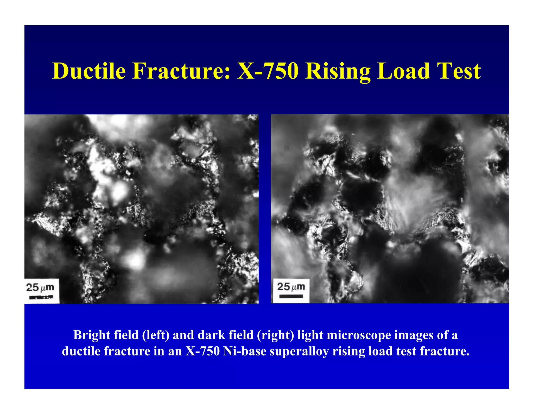
2. Catastrophic failures of all-
welded T-2 Tankers and
Liberty Ships in WW2 focused
attention on the field of failure
analysis and led to the
development of fractography
and fracture mechanics
3. Duplessis Bridge, Three Rivers,
Quebec, Canada
Ohio River Bridge
Bridge failures have also
focused attention on
fractography, fracture
mechanics and failure analysis.
Silver Bridge Between Ohio and
West Virginia
4. Despite Our Knowledge, Bridge Failures Still Occur!
Failure of bridge over the Tennessee River near Clifton, TN, reported in
newspapers on May 16, 1995.
5. Reasons for Conducting a Failure Analysis
• Determine the cause(s) of the failure
• Prevent similar problems with identical components
• Improve the performance of future parts
• Absolve your company of liability
• Pass the liability to others
6. Causes of Failure
• Poor Design
• Imperfections in Materials
• Imperfections in Manufacture/Fabrication
• Overloading/Service Abuse
• Improper Maintenance or Repair
• Environmental Effects
• Combinations of the above
7. Sequence for Examination of
Fractured Components
• Visually survey the entire component to obtain an overall
understanding of its operation
• Classify the fracture from a macroscopic standpoint as
ductile, brittle, fatigue, torsion, etc.
• Determine the origin(s) by tracing the fracture back to its
starting point(s)
• Determine the loading (tension, compression, etc), stress
level and orientation
• Use macrofractography to determine the fracture mode
and confirm the fracture mechanism
9. Transgranular: Cracking across grains
without preference for grain boundaries
Intergranular: Cracking between grains, the
crack propagates in the grain boundaries
10. • Ductile
• Brittle
• Fatigue
• Torsion
• Stress Corrosion Cracking
• Liquid Metal Embrittlement
• Hydrogen Embrittlement and HIC
• Creep
• Wear
11. A ductile fracture suggests that the design,
materials and manufacture were all done
properly and the part was overloaded in
service. It may be that the applied stresses
are now greater than the part was
originally designed to withstand.
12. 70 °F, Burst at 8500 psi
-50 °F, Burst at 9000 psi
7.375 inch diameter, 0.125 inch thick 1030
carbon steel vessel, design strength 4475 psi
13. Top View Side View
Large shear lips, substantial “necking” down
16. Ductile Fracture: X-750 Rising Load Test
Bright field (left) and dark field (right) light microscope images of a
ductile fracture in an X-750 Ni-base superalloy rising load test fracture.
17. Ductile Fracture: X-750 Rising Load Test
Secondary electron SEM image of a ductile fracture of X-750 Ni-base
superalloy rising load test fracture.
18. SEM SEI – PH 13-8Mo Stainless Steel Tensile Fracture
19. Brittle fractures suggest that the
design, manufacture or materials
quality were improper for the safe use
of the part.
20. Top View Side View
Small shear lips, no visible “necking” down
22. Bright field (left) and dark field (right) views by light microscopy of a
brittle cleavage fracture in Fe – 2.5% Si broken at –173 °C.
23. SEM SEI, 14 mm WD SEM BSEI, 14 mm WD
Same area viewed with the Everhard-Thornley detector;
the backscattered image is easier to interpret
24. Direct and Indirect Views of a Brittle Fracture
LOM - Profile LOM - Fracture SEM - Fracture
LOM - Replica SEM - Replica TEM - Replica
25. Unusual Intergranular Fracture in Fe-Cr-Al Alloy
Dark Field LOM SEM SE Image
Two additional views of the unusual stepped intergranular fracture in the
Fe-Cr-Al alloy.
26. Bright field (left) and dark field (right) light microscopy images of an
intergranular fracture in a Ni-base superalloy.
27. Secondary electron (left) and backscattered electron (E-T) SEM images of the
intergranular fracture in a Ni-base superalloy.
28. X-60 Line Pipe Tested 8 °F Above DWTT
Full scale line pipe test, loaded to 40% of the yield strength, tested at 56 °F, 8
°F above the 50% shear area drop-weight tear test transition temperature
(+48 °F). A 30-grain charge was detonated beneath an 18-inch notch cut in
the pipe. The crack speed was 279 fps. The crack propagated 33-inch in full
shear and then 18-inch in tearing shear before stopping.
29. X-60 Line Pipe Tested 2 °F Below DWTT
After a small amount of brittle fracture, the crack became ductile and stopped;
average crack speed was 566 fps.
30. X-60 Line Pipe Tested 10 °F Below DWTT
Fracture was brittle, ending in ductile shear; average crack speed was 1550 fps.
31. X-60 Line Pipe Tested 40 °F Below DWTT
This line pipe fractured in a wave pattern for a full wave-length by cleavage
with <10% shear area present, then changed to full shear and tore
circumferentially 19-inch before stopping. The crack speed was 2215 fps.
32. Fatigue fractures occur due to repeated
cyclic loading below the static yield
strength. It is important to determine if
fatigue was high-cycle or low-cycle, as
the remedies for each are different.
33. - - - - - - - - - H i g h nominal s t r e s s - - - - - - - - - -
No stress
,- concentrotion-,
Mildstress
,-- concentration------..
Severe stress
,- concentrat,on-----,
- - - - - - - - - - L o w nominal s t r e s s - - - - - - - - - -
Nostress
,- conceritrotion------..
Mild stress
,-- concentration-,
Severe stress
,-------concentration -,
34.
35.
36. Fatigue in Carbon Steel
Fatigue crack grown from a notch in a
carbon steel (above and above right, 2%
nital).
45. S J . l l l f J g
JUJWJJJJJ.IQW'J[ pug UOJSO.l.IO:)
46. 500x
Secondary cracks in 4340 fasteners that failed by SCC in sea water; etched with
saturated picric acid + 0.5% HCl + wetting agent at 80C to show the P GBs.
58. Segregation produced martensite in segregated areas which lead to microcracks
that propagated during backward extrusion (under poor conditions), 4% picral.
69. Two of several tie plate punches broke soon after being placed in service
because the surfaces were completely decarburized in heat treatment (nital).
100 µm 100 µm
70. Decarburized
surfaces revealed
by cold etching.
Hardnesses of
the decarburized
surfaces ranged
from 48 to 57
HRC. The
interior was 59
HRC.
The Cr-plated blanking die failed in service
because the plated surface was decarburized and
too low in strength to support the service stresses.
71. 100 µm 14 µm
Cr Plating
Decarburized surface (left) below the chromium-plated surface had
inadequate strength to support the plating. The internal, correct structure is
shown at right (nital).
72. 14 µm
This A2 punch failed early in service because it was not tempered after
quenching.
74. This S7 angle shear blade failed prematurely due to grinding abuse caused by
an unstable microstructure at the surface.
75. Surface Interior
The surface was accidentally carburized and the austenitizing temperature
was excessive producing a coarse grained interior and coarse plate martensite
and retained austenite at the surface (nital).
14 µm 14 µm
76. This A 490 (4140) bolt
broke during the head
integrity test the day after
installation. The bolts
were tempered at about
900 °F, at the nose of the
temper-embrittlement
curve, and were above the
hardness specification.
77. Fracture at Origin (Circular Area) Fracture at center of bolts
The A 490 bolts broke because they were temper embrittled during heat
treatment. A re-tempered bolt, at the proper hardness, was torqued to failure and
the fracture was ductile at the required test load.
79. Normalize, Quenched and Tempered to 321/341 HB, Then Fractured to
Detect Facets Indicative of Over Heating Prior to Forging
80. 2200F 2250F 2300F 2350F 2400F 2450F 2500F
Forging Temperature
Specimens were normalized, quenched and tempered to 321/341 HB, then
fractured to look for over-heating facets
81. 2200 °F 2500 °F
ASTM A508 Class II Reactor Forging Steel
82. In non-Al-Killed sheet
steels, the sheet is roller
leveled, 1-2%
reduction, to suppress
the yield point. It must
be formed within about
6 months or the
nitrogen will become
free and the yield point
will return.
83.
84. Aqueous saturated picric acid, with 1% HCl and a wetting agent, Nacconol
90G, at 80 °C revealed the prior-austenite grain boundaries. The hardness was
too high, 35-38 HRC, making the steel sensitive to Cl- ion stress-corrosion
cracking. Note the pronounced intergranular crack pattern.
20 µm 20 µm
85. Fracture appearance of a typical failed bolt; arrows point to the origin at
the surface. There is some corrosion on the surface (3x, 6x)
86. The bolts were not tempered making them sensitive to SCC (53-57 HRC),
2% nital etch.
20 µm
20 µm
87. 20 µm
The core consisted of as-quenched martensite, pearlite and grain boundary ferrite at
26-28 HRC, 2% Nital
88. Sensitization of Austenitic Stainless Steel
Planar surface of a sensitized austenitic stainless steel showing intergranular
“grain dropping” corrosion.
89. Sensitized Austenitic Stainless Steel
Cross sectional view of the intergranular attack in the sensitized
austenitic stainless steel (not etched).
92. SEM SEI Acetic Glyceregia
Sensitization precipitated carbides on the grain boundaries and
reduced the impact energy by 40%
93. Electrolytic KOH
Sigma phase precipitated from excessive ferrite in this cast HH stainless steel
furnace hook causing it to fracture extensively.
94. SEM SEI Acetic Glyceregia
High-temperature service precipitated sigma converting all of the delta
ferrite in 308 stainless steel weld metal. This reduced the impact energy to 7%
of the original level.
96. Before Service After 1000 h at 700 °F
Vilella’s reagent revealed only carbides before service and dark-
etching grain boundaries after service.
97. Views of fracture edge and secondary cracks (left) and internal cracks in
T-250 mobile assault bridges (mod. Fry’s etch).
98. SEM view of the intergranular fracture (left) and TEM extraction
fractograph of the fracture with embrittling Ti(C,N) precipitates.
99. Commutator side of axle fracture
and intergranular crack pattern
typical of liquid-metal
embrittlement (1072 carbon steel)
100. Partially broken and completely broken Gleeble test specimens coated
with Cu and tested at 1100 °C (2% nital etch). Arrows point to copper in
the grain boundaries.
101. This test specimen was used to simulate the failure of the axle. Note the
grain-boundary copper phase from LME (4% picral).
50 µm
102.
103. Frictional heating re-austenitzed the surface producing as-quenched martensite
upon cooling which promoted cracking in this straighter roll (2% nital).
104. Frictional heat produced as-quenched martensite at the cutting edge of this
scrap metal chopper knife causing fracture (3% nital).
105. Frictional heating from spinning wheels caused re-austenization of the pearlitic
rail structure and martensite formation that caused a spall to form. The surface
hardness was 64 HRC. The arrows point to grain-boundary ferrite that formed
due to the limited hardenability during air cooling. Beneath this surface zone is the
original fine pearlitic structure of an as-rolled rail (4% picral etch).
111. Plot of average number of
striations per micrometer versus
the distance from near the origin
to final rupture. A least square
regression curve was fitted to the
data. Graphical integration
showed that about 250,000 stress
cycles occurred over this distance
on the fracture.
112. Results of replication
of a controlled fatigue
crack in a 1030 carbon
steel specimen used to
demonstrate the
precision of the
estimation of the
number of stress
cycles to grow a
fatigue crack from
striation data.