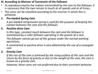
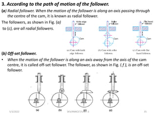
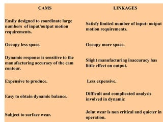
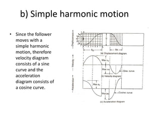
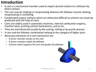
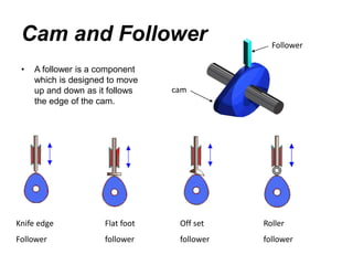
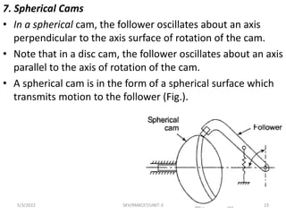
1) The document discusses cam and follower mechanisms including definitions, classifications, and terminology.
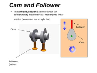
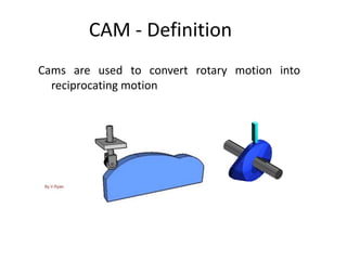
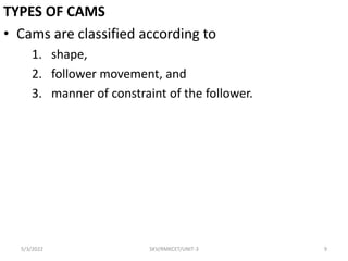
2) Cams are used to convert rotary motion to reciprocating or oscillating motion and are classified based on shape, follower movement, and manner of constraint.
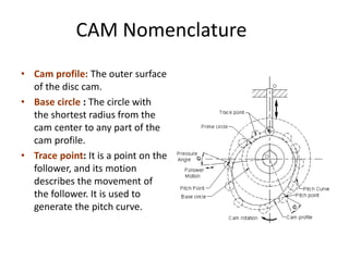
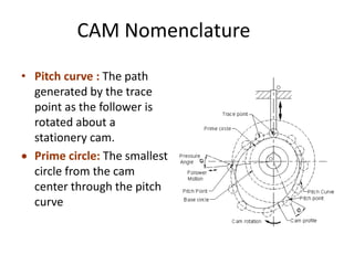
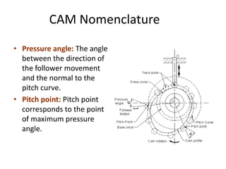
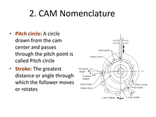
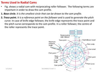
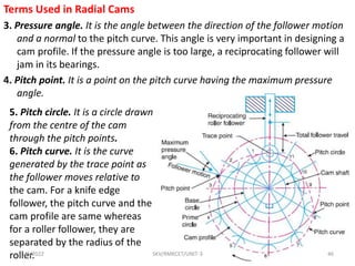
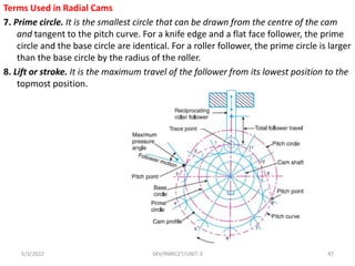
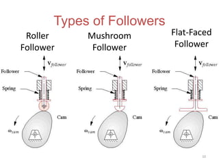
3) Key terms discussed include cam profile, base circle, trace point, pitch curve, pressure angle, and pitch point. Radial cams with reciprocating roller followers are examined in detail.
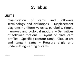
![I. According to Shape
1) Wedge and Flat Cams
• A wedge cam has a wedge W which, in general, has a
translational motion.
• The follower F can either translate [Fig.(a)] or oscillate [Fig.(b)].
• A spring is, usually, used to maintain the contact between the
cam and the follower.
• In Fig.(c), the cam is stationary and the follower constraint or
guide G causes the relative motion of the cam and the follower.
5/3/2022 SKV/RMKCET/UNIT-3 17](https://image.slidesharecdn.com/skvunit3-220503144202/85/CAM-introductions-17-320.jpg)
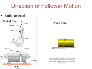
![2. Radial or Disc Cams
• A cam in which the follower moves radially from
the centre of rotation of the cam is known as a
radial or a disc cam (Fig. (a) and (b)].
• Radial cams are very popular due to their simplicity
and compactness.
5/3/2022 SKV/RMKCET/UNIT-3 18](https://image.slidesharecdn.com/skvunit3-220503144202/85/CAM-introductions-18-320.jpg)
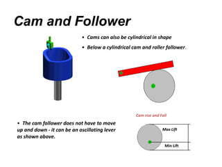
![4. Cylindrical Cams
• In a cylindrical cam, a cylinder which has a circumferential contour cut in the
surface, rotates about its axis.
• The follower motion can be of two types as follows: In the first type, a groove is cut
on the surface of the cam and a roller follower has a constrained (or positive)
oscillating motion [Fig.(a)].
• Another type is an end cam in which the end of the cylinder is the working surface
(b).
• A spring-loaded follower translates along or parallel to the axis of the rotating
cylinder.
5/3/2022 SKV/RMKCET/UNIT-3 20](https://image.slidesharecdn.com/skvunit3-220503144202/85/CAM-introductions-20-320.jpg)
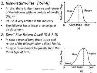
![3. Dwell-Rise-Dwell-Return-Dwell
(D-R-D-R-D)
• It is the most widely used type of
cam.
• The dwelling of the cam is followed
by rise and dwell and subsequently
by return and dwell as shown in
rig. (c).
• In case the return of the follower is
by a fall [Fig.(d)], the motion may
be known as Dwell-Rise-Dwell (D-
R-D).
5/3/2022 SKV/RMKCET/UNIT-3 26](https://image.slidesharecdn.com/skvunit3-220503144202/85/CAM-introductions-26-320.jpg)