This document discusses cams and cam mechanisms. It defines a cam as a rotating machine element that imparts reciprocating or oscillating motion to another element called a follower. The document then describes different types of followers based on their contacting surface and motion. It also discusses terms used in radial cams such as base circle, trace point, pressure angle, and pitch curve. The document concludes by describing different motions a follower may have, including uniform velocity, and providing displacement, velocity, and acceleration diagrams for when the follower moves with uniform velocity.
Reconstruction of globoidal cam follower motion curve based on B-splineIJRES Journal
Due to the development of the CNC technology, manufacturing the complex surface is becoming
more and more easier. Globoidal cam is an important part of intermittent motion mechanism, so nowadays
machining the globoidal cam by CNC machine is a new research area. In general, the contour line of the
globoidal cam can be described by the follower motion curve. But because of the property of the globoidal
cam, its contour surface is non-development, so the follower motion curve cannot defined by mathematical
expression. In order to solve this problem, this paper attempts to reconstruct the follower motion curve based on
B-spline by the help of MATLAB. In this research, 3 common follower motion laws are discussed: modified
constant velocity, modified trapezoid and modified sine. By observing the results, it can be said that
reconstruction of the follower motion curve is similar to the original curve which defined by mathematical
equation.
A cam is a rotating machine element which gives reciprocating or oscillating motion to another element known as the follower.Though the cams may be classified in many ways, among them we can classify:
1. Radial or disc cam.
2. Cylindrical cam.
NO1 Uk best vashikaran specialist in delhi vashikaran baba near me online vas...Amil Baba Dawood bangali
Contact with Dawood Bhai Just call on +92322-6382012 and we'll help you. We'll solve all your problems within 12 to 24 hours and with 101% guarantee and with astrology systematic. If you want to take any personal or professional advice then also you can call us on +92322-6382012 , ONLINE LOVE PROBLEM & Other all types of Daily Life Problem's.Then CALL or WHATSAPP us on +92322-6382012 and Get all these problems solutions here by Amil Baba DAWOOD BANGALI
#vashikaranspecialist #astrologer #palmistry #amliyaat #taweez #manpasandshadi #horoscope #spiritual #lovelife #lovespell #marriagespell#aamilbabainpakistan #amilbabainkarachi #powerfullblackmagicspell #kalajadumantarspecialist #realamilbaba #AmilbabainPakistan #astrologerincanada #astrologerindubai #lovespellsmaster #kalajaduspecialist #lovespellsthatwork #aamilbabainlahore#blackmagicformarriage #aamilbaba #kalajadu #kalailam #taweez #wazifaexpert #jadumantar #vashikaranspecialist #astrologer #palmistry #amliyaat #taweez #manpasandshadi #horoscope #spiritual #lovelife #lovespell #marriagespell#aamilbabainpakistan #amilbabainkarachi #powerfullblackmagicspell #kalajadumantarspecialist #realamilbaba #AmilbabainPakistan #astrologerincanada #astrologerindubai #lovespellsmaster #kalajaduspecialist #lovespellsthatwork #aamilbabainlahore #blackmagicforlove #blackmagicformarriage #aamilbaba #kalajadu #kalailam #taweez #wazifaexpert #jadumantar #vashikaranspecialist #astrologer #palmistry #amliyaat #taweez #manpasandshadi #horoscope #spiritual #lovelife #lovespell #marriagespell#aamilbabainpakistan #amilbabainkarachi #powerfullblackmagicspell #kalajadumantarspecialist #realamilbaba #AmilbabainPakistan #astrologerincanada #astrologerindubai #lovespellsmaster #kalajaduspecialist #lovespellsthatwork #aamilbabainlahore #Amilbabainuk #amilbabainspain #amilbabaindubai #Amilbabainnorway #amilbabainkrachi #amilbabainlahore #amilbabaingujranwalan #amilbabainislamabad
Explore the innovative world of trenchless pipe repair with our comprehensive guide, "The Benefits and Techniques of Trenchless Pipe Repair." This document delves into the modern methods of repairing underground pipes without the need for extensive excavation, highlighting the numerous advantages and the latest techniques used in the industry.
Learn about the cost savings, reduced environmental impact, and minimal disruption associated with trenchless technology. Discover detailed explanations of popular techniques such as pipe bursting, cured-in-place pipe (CIPP) lining, and directional drilling. Understand how these methods can be applied to various types of infrastructure, from residential plumbing to large-scale municipal systems.
Ideal for homeowners, contractors, engineers, and anyone interested in modern plumbing solutions, this guide provides valuable insights into why trenchless pipe repair is becoming the preferred choice for pipe rehabilitation. Stay informed about the latest advancements and best practices in the field.
Overview of the fundamental roles in Hydropower generation and the components involved in wider Electrical Engineering.
This paper presents the design and construction of hydroelectric dams from the hydrologist’s survey of the valley before construction, all aspects and involved disciplines, fluid dynamics, structural engineering, generation and mains frequency regulation to the very transmission of power through the network in the United Kingdom.
Author: Robbie Edward Sayers
Collaborators and co editors: Charlie Sims and Connor Healey.
(C) 2024 Robbie E. Sayers
Final project report on grocery store management system..pdfKamal Acharya
In today’s fast-changing business environment, it’s extremely important to be able to respond to client needs in the most effective and timely manner. If your customers wish to see your business online and have instant access to your products or services.
Online Grocery Store is an e-commerce website, which retails various grocery products. This project allows viewing various products available enables registered users to purchase desired products instantly using Paytm, UPI payment processor (Instant Pay) and also can place order by using Cash on Delivery (Pay Later) option. This project provides an easy access to Administrators and Managers to view orders placed using Pay Later and Instant Pay options.
In order to develop an e-commerce website, a number of Technologies must be studied and understood. These include multi-tiered architecture, server and client-side scripting techniques, implementation technologies, programming language (such as PHP, HTML, CSS, JavaScript) and MySQL relational databases. This is a project with the objective to develop a basic website where a consumer is provided with a shopping cart website and also to know about the technologies used to develop such a website.
This document will discuss each of the underlying technologies to create and implement an e- commerce website.
Hybrid optimization of pumped hydro system and solar- Engr. Abdul-Azeez.pdffxintegritypublishin
Advancements in technology unveil a myriad of electrical and electronic breakthroughs geared towards efficiently harnessing limited resources to meet human energy demands. The optimization of hybrid solar PV panels and pumped hydro energy supply systems plays a pivotal role in utilizing natural resources effectively. This initiative not only benefits humanity but also fosters environmental sustainability. The study investigated the design optimization of these hybrid systems, focusing on understanding solar radiation patterns, identifying geographical influences on solar radiation, formulating a mathematical model for system optimization, and determining the optimal configuration of PV panels and pumped hydro storage. Through a comparative analysis approach and eight weeks of data collection, the study addressed key research questions related to solar radiation patterns and optimal system design. The findings highlighted regions with heightened solar radiation levels, showcasing substantial potential for power generation and emphasizing the system's efficiency. Optimizing system design significantly boosted power generation, promoted renewable energy utilization, and enhanced energy storage capacity. The study underscored the benefits of optimizing hybrid solar PV panels and pumped hydro energy supply systems for sustainable energy usage. Optimizing the design of solar PV panels and pumped hydro energy supply systems as examined across diverse climatic conditions in a developing country, not only enhances power generation but also improves the integration of renewable energy sources and boosts energy storage capacities, particularly beneficial for less economically prosperous regions. Additionally, the study provides valuable insights for advancing energy research in economically viable areas. Recommendations included conducting site-specific assessments, utilizing advanced modeling tools, implementing regular maintenance protocols, and enhancing communication among system components.
Industrial Training at Shahjalal Fertilizer Company Limited (SFCL)MdTanvirMahtab2
This presentation is about the working procedure of Shahjalal Fertilizer Company Limited (SFCL). A Govt. owned Company of Bangladesh Chemical Industries Corporation under Ministry of Industries.
Welcome to WIPAC Monthly the magazine brought to you by the LinkedIn Group Water Industry Process Automation & Control.
In this month's edition, along with this month's industry news to celebrate the 13 years since the group was created we have articles including
A case study of the used of Advanced Process Control at the Wastewater Treatment works at Lleida in Spain
A look back on an article on smart wastewater networks in order to see how the industry has measured up in the interim around the adoption of Digital Transformation in the Water Industry.
Water Industry Process Automation and Control Monthly - May 2024.pdf
4 12875 515
1. Cams
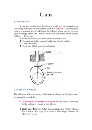
1. Introduction:-
A cam is a rotating machine element which gives reciprocating or
oscillating motion to another element known as follower. The cam rotates
usually at constant speed and drives the follower whose motion depends
upon the shape of the cam. Almost always the cam is the driver and the
follower is the driven.
In a cam mechanism, the three essential members are:
The cam which has a curved surface or straight surface,
The follower and
The frame which supports and guides.
2-Types of Followers:
The followers which are having either reciprocating or oscillating motion,
are generally classified as:
According to the surface in contact. The followers, according
to the surface in contact, are as follows :
Knife edge follower: When the contacting end of the follower
has a sharp knife edge, it is called a knife edge follower, as
shown in Fig. (a).
2. Roller follower: When the contacting end of the follower is a
roller, it is called a roller follower, as shown in Fig. (b).
Flat faced or mushroom follower: When the contacting end of
the follower is a perfectly flat face, it is called a flat-faced
follower, as shown in Fig. (c).
According to the motion of the follower:- The followers,
according to its motion, are of the following two types:
(a) Reciprocating or translating follower. When the follower
reciprocates in guides as the cam rotates uniformly, it is known as
reciprocating or translating follower. The followers as shown in
Fig. (a) to (c) are all reciprocating or translating followers.
(b) Oscillating or rotating follower. When the uniform rotary
motion of the cam is converted into predetermined oscillatory
motion of the follower, it is called oscillating or rotating follower.
The follower, as shown in Fig. below, is an oscillating or rotating
follower.
3. According to the path of motion of the follower :- The followers,
according to its path of motion, are of the following two types:
Radial follower. When the motion of the follower is along an axis
passing through the centre of the cam, it is known as radial
follower. The followers, as shown in Fig. (a) to (c), are all radial
followers.
Off-set follower. When the motion of the follower is along an axis
away from the axis of the cam centre, it is called off-set follower.
The follower, as shown in Fig. below, is an off-set follower.
Note: Radial or disc cam. In radial cams, the follower reciprocates or
oscillates in a direction perpendicular to the cam axis.
3- Terms Used in Radial Cams:
Fig. below shows a radial cam with reciprocating roller follower. The
following terms are important in order to draw the cam profile.
1. Base circle. It is the smallest circle that can be drawn to the cam
profile.
2. Trace point. It is a reference point on the follower and is used to
generate the pitch curve. In case of knife edge follower, the knife edge
represents the trace point and the pitch curve corresponds to the cam
profile. In a roller follower, the centre of the roller represents the trace
point.
3. Pressure angle. It is the angle between the direction of the follower
motion and a normal to the pitch curve. This angle is very important in
designing a cam profile. If the pressure angle is too large, a reciprocating
follower will jam in its bearings.
4. 4. Pitch point. It is a point on the pitch curve having the maximum
pressure angle.
5. Pitch circle. It is a circle drawn from the centre of the cam through the
pitch points.
6. Pitch curve. It is the curve generated by the trace point as the follower
moves relative to the cam. For a knife edge follower, the pitch curve and
the cam profile are same whereas for a roller follower, they are separated
by the radius of the roller.
7. Prime circle. It is the smallest circle that can be drawn from the centre
of the cam and tangent to the pitch curve. For a knife edge and a flat face
follower, the prime circle and the base circle are identical. For a roller
follower, the prime circle is larger than the base circle by the radius of the
roller.
8. Lift or stroke. It is the maximum travel of the follower from its lowest
position to the topmost position.
3- Motion of the Follower:-
The follower, during its travel, may have one of the following
motions.
1. Uniform motion or uniform velocity,
2. Simple harmonic motion.
3. Uniform acceleration and uniform retardation.
4. Cycloidal motion.
5. 1- Displacement, Velocity and Acceleration Diagrams when
the Follower Moves with Uniform Velocity:-
The displacement, velocity and acceleration diagrams when a knife-
edged follower moves with uniform velocity are shown in Fig. (i) (a), (b)
and (c) respectively. The abscissa (base) represents the time (i.e. the
number of seconds required for the cam to complete one revolution) or it
may represent the angular displacement of the cam in degrees. The
ordinate represents the displacement, or velocity or acceleration of the
follower.
Since the follower moves with uniform velocity during its rise and
return stroke, therefore the slope of the displacement curves must be
constant. In other words, AB1 and C1D must be straight lines. A little
consideration will show that the follower remains at rest during part of
the cam rotation. The periods during which the follower remains at rest
are known as dwell periods, as shown by lines B1C1 and DE in Fig. (i)
(a). From Fig. (i) (c), we see that the acceleration or retardation of the
follower at the beginning and at the end of each stroke is infinite. This is
due to the fact that the follower is required to start from rest and has to
gain a velocity within no time. This is only possible if the acceleration or
retardation at the beginning and at the end of each stroke is infinite. These
conditions are however, impracticable.
(i) Displacement, velocity and
acceleration diagrams when the
follower moves with uniform velocity.
(ii) Modified displacement, velocity
and acceleration diagrams when the
follower moves with uniform velocity.
6. In order to have the acceleration and retardation within the finite
limits, it is necessary to modify the conditions which govern the motion
of the follower. This may be done by rounding off the sharp corners of
the displacement diagram at the beginning and at the end of each stroke,
as shown in Fig. (ii) (a). By doing so, the velocity of the follower
increases gradually to its maximum value at the beginning of each stroke
and decreases gradually to zero at the end of each stroke as shown in Fig.
(ii) (b). The modified displacement, velocity and acceleration diagrams
are shown in Fig. (ii). The round corners of the displacement diagram are
usually parabolic curves because the parabolic motion results in a very
low acceleration of the follower for a given stroke and cam speed.
Example(1):- A cam is to give the following motion to a knife-edged
follower : 1. Outstroke during 60° of cam rotation ; 2. Dwell for the next
30° of cam rotation ; 3. Return stroke during next 60° of cam rotation,
and 4. Dwell for the remaining 210° of cam rotation.
The stroke of the follower is 40 mm and the minimum radius of the
cam is 50 mm. The follower moves with uniform velocity during both the
outstroke and return strokes. Draw the profile of the cam when (a) the
axis of the follower passes through the axis of the cam shaft, and
(b) the axis of the follower is offset by 20 mm from the axis of the cam
shaft.