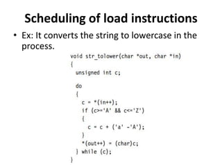
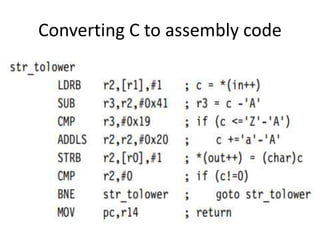
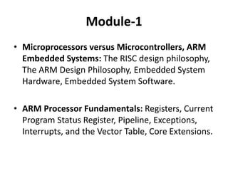
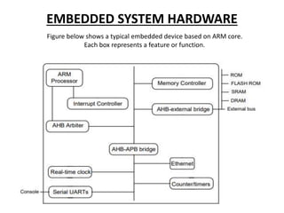
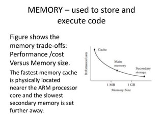
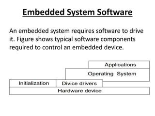
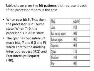
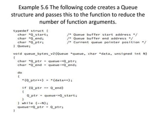
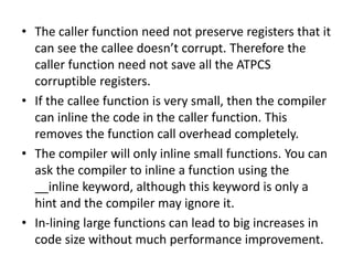
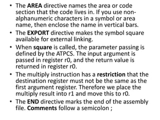
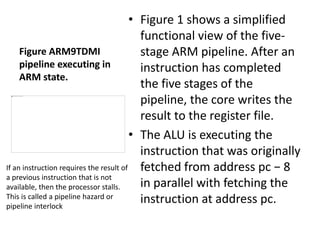
This document provides an overview of microcontrollers and embedded systems using ARM architecture. It discusses the differences between microprocessors and microcontrollers, as well as RISC and CISC designs. The ARM design philosophy focuses on low power consumption. An ARM-based embedded system typically includes an ARM processor, controllers, peripherals connected via an AMBA bus. Software includes boot code, an operating system, device drivers, and applications. The ARM instruction set and registers are also described.


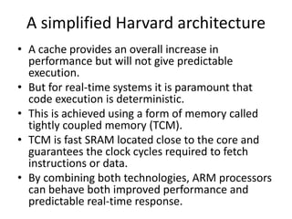


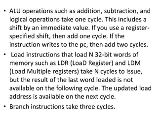
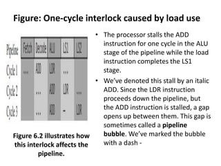
![LDR r1, [r2, #4]
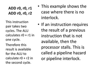
ADD r0, r0, r1
• This instruction pair takes three
cycles. The ALU calculates the
address r2 + 4 in the first cycle
while decoding the ADD
instruction in parallel.
• However, the ADD cannot
proceed on the second cycle
because the load instruction has
not yet loaded the value of r1.
• Therefore the pipeline stalls for
one cycle while the load
instruction completes the LS1
stage. Now that r1 is ready, the
processor executes the ADD in
the ALU on the third cycle.
This example
shows a one-
cycle interlock
caused by load
use.](https://image.slidesharecdn.com/mesppt-240209165419-05f9fae0/85/MES-PPT-pptx-83-320.jpg)