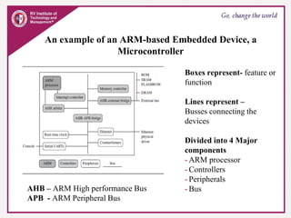
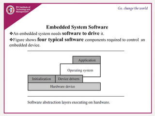
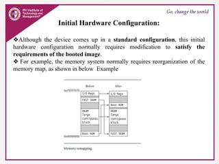
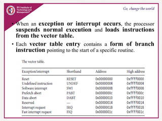
Module-1
Microcontroller and Embedded
Systems
18CS44
ARM Microprocessor Basics
❖ARM: Advance RISC Machine.
❖ARM was established as a joint venture between Acorn, Apple and VLSI
in November 1990.
❖ARM is the industry's leading provider of 16/32-bit embedded RISC
microprocessor solutions.
❖The company licenses its high-performance, low-cost, power-designs to
leading international electronics companies.
❖ARM provides comprehensive support required in developing a complete
system.
ARM Embedded
Systems
• The ARM processor is a key component of many successful 32-bit
embedded systems.
• You probably own one yourself and may not even realize it!
• ARM cores are widely used in mobile phones, handheld devices, and a
many other everyday portable consumer devices.
• The first ARM prototype name ARM1 was designed in 1985 and continues
to improve through constant technical innovation leading to ARM2,
ARM3, ARM4, ARM5, ARM6, ARM7, ARM8, ARM9… ARM Cortex.
• Approximately one billion ARM processors had been shipped worldwide by the
end of 2001.
• Now, ARM sales is 7 times more than the worlds population.
• The ARM core is not a single core, but a whole family of designs sharing similar
design principles and a common instruction set.
• Example, ARM7TDMI is one of the most successful ARM core widely used in
majority of the devices.
• It provides up to 120 Dhrystone MIPS, high code density and low power
consumption, making it ideal for mobile embedded devices.
• ARM has adopted the RICS design philosophy.
❖ARM Holdings is a technology company headquartered in
Cambridge, England, UK. The company is best known for its processors,
although it also designs, licenses and sells software development tools
under the RealView and KEIL brands, systems and platforms, system-on-a-
chip infrastructure and software.
❖ARM do not make ICs !!!
❖ARM grant license of core to different silicon vendors like ATMEL,
NXP, Cirrus logic etc.. These companies make IC’S.
Examples are: LPC2148 from NXP, AT91RM9200 from ATMEL.
❖ARM processors can be used in any domain
❖Mainly ARM processors are used in Handheld devices, Robotics,
Automation, Consumer Electronics.
❖ARM processors are available for almost every domain.
Apple iPhone ARM11 Motorola Z8 Smart phone
ARM11
ARM Based Products
Blackberry ARM11 Nokia E90 Communicator ARM11
iPOD ARM7TDMI
Juice Box
Low cost Multimedia player
ARM7TDMI
Lego Mindstrome Robot
ARM7
Paison Series game
consoles ARM7TDMI
The RISC design philosophy
❑ The ARM processors uses a RISC architecture.
❑ RICS-Reduced Instruction Set Computing
Instructions:
❑ RISC is a design philosophy aims to provide few simple but powerful
instructions that execute within a single clock cycle.
❑ The RISC philosophy aims to reduce the complexity of instructions
performed by the hardware because it is easier to provide greater
flexibility and intelligence in software rather than hardware.
❑ RISC design places greater burden/load on the compiler.
❑ Traditional complex instruction set computer (CISC) relies more on the
hardware (processor) for instruction functionality, as CISC instructions
are more complicated.
Pipelining
❑ Instruction execution is done in pipelined fashion
❑ Ideal pipeline stage clock cycle is 1 to have maximum throughput.
❑Instructions are executed in pipeline stages.
ARM7 is a 3 stage pipelined processor
First stage – fetches the instruction
Second Stage - Decodes the instruction and fetches
the operands
Third Stage - Executes the instruction and stores
the result
Registers
❑ RISC machines have a large general-purpose register set.
❑ Any register can contain either data or an address.
❑ Registers act as the fast local memory store for all data processing
operations.
❑ In contrast, CISC processors have dedicated registers for specific
purposes.
Load-store architecture
❑ Processor operates only on data held in registers.
❑ Separate load and store instructions transfer data between the
register bank and external memory.
❑ Memory accesses are costly, so separating memory accesses
from data processing provides an advantage because you can use
data items held in the register bank multiple times without
needing multiple memory accesses.
❑ In contrast, with a CISC design the data processing operations
can act on memory directly.
⮚These RICS design rules allow a RISC processor to be simpler,
and thus the core can operate at higher clock frequencies.
⮚ In contrast, traditional CISC processors are more complex and
operate at lower clock frequencies.
⮚Over the course of two decades, however, the distinction between
RISC and CISC has blurred as CISC processors have implemented
more RISC concepts.
RISC : Reduced Instruction Set
Computing
❖ Lesser number of fixed length instructions.
❖ Fewer addressing modes.
❖ Increased pipelining and increased execution speed.
❖ Orthogonal instruction set(Allows each instruction to operate on any
register and use any addressing mode).
❖ Operations are performed on registers only. Memory operations are load
and store. (Load Store Architecture).
❖ A large number of register are available.
❖ Programmer needs to write more code to execute a task since the
instructions are simpler once.
❖ Instruction take one clock cycle. The average clock cycle per instruction
(CPI) is 1.5.
The ARM Design Philosophy
RICS features accepted by ARM
❑ A large set of uniform register file
❑ A load store architecture
❑ Uniform and fixed length (32-bit) instruction fields
❑ Three address instruction formats
The ARM Design Philosophy
RICS features rejected by ARM
❑ Register windows – because they occupy large chip area.
❑ Delayed Branches
❑ Single cycle execution of all instructions.
Additional Features in ARM architecture
❑ Has control over both the ALU and the barrel shifter in every
data pre-processing instructions.
❑Auto increment and auto decrement addressing modes to
optimize program loops.
❑Load and store multiple instructions to maximize execution
throughput.
❑Conditional execution of all instructions to maximize data
throughput.
Instruction Set for Embedded System
The ARM instruction set differs from pure RISC definition in several ways
that make the ARM instruction set suitable for embedded applications.
❖ Variable cycle execution for certain instruction
❖ Barrel shifter: Inline barrel shifter for more complex instructions.
❖ Conditional execution facility in majority of the instructions.
❖ Enhanced instruction – Enhanced DSP instructions were added to the standard
ARM instruction.
❖ Thumb state (16 bit- instruction set) – improves the code density by 30% to
35% over 32-bit fixed length instructions
Embedded System Hardware
❖Embedded systems are designed to control many different devices,
-- from small sensors found on a production line, to
-- the real-time control systems used on a NASA space probe.
❖All these devices use a combination of software and hardware
components.
❖Each component is designed to provide higher efficiency and, is
designed for future extension and expansion.
An example of an ARM-based Embedded Device, a
Microcontroller
Boxes represent- feature or
function
Lines represent –
Busses connecting the
devices
Divided into 4 Major
components
- ARM processor
- Controllers
- Peripherals
- Bus
AHB – ARM High performance Bus
APB - ARM Peripheral Bus
ARM Processor
❖Controls the embedded device.
❖Different versions of the ARM processor are available to suit the desired
operating characteristics.
❖An ARM processor comprises
- a core (the execution engine that processes instructions and manipulates
data)
plus
- the surrounding components that interface it with a bus (include
memory management and caches.)
Controllers
❖Helps coordinate important functional blocks of the system.
❖Two commonly found controllers are
-interrupt controller and
-memory controllers.
Peripherals
❖Provides input-output capability external to the chip.
-includes serial I/O, Parallel I/O, Timers counters and clock
circuits
❖Responsible for the uniqueness of the embedded device.
Bus
❖Supports communicate between different parts of the device.
AHB, APB
ARM Bus Technology
❖Embedded systems use different bus technologies than those
designed for x86 PCs.
❖PCs bus technology uses Peripheral Component Interconnect
(PCI) bus, to connect devices such as
- video cards and
-hard disk controllers to the x86 processor bus.
❖ This technology is external or off-chip (i.e., the bus is designed to
connect mechanically and electrically to devices external to the chip) and is
built into the motherboard of a PC.
❖Embedded devices use an on-chip bus that is internal to the chip and that
allows different peripheral devices to be interconnected with an ARM core.
❖There are two different classes of devices attached to the ARM on chip
bus.
- A bus master: a logical device capable of initiating a data transfer
with another device across the same bus. The ARM processor core is the bus
master.
- Bus slaves: logical devices capable only of responding to a
transfer request from a bus master device. All peripherals are bus slaves
❖On chip ARM bus has two architecture levels.
- Physical level covers the electrical characteristics and bus width
(16, 32, or 64 bits).
- Protocol level covers the logical rules that govern the
communication between the processor and a peripheral.
❖ARM is primarily a design company. It does not/rarely implements the
electrical characteristics of the bus, but it specifies the bus protocol.
AMBA Bus Protocol
❖AMBA - Advanced Microcontroller Bus Architecture.
❖ Was introduced in 1996 and widely adopted as the on-chip bus
architecture used for ARM processors.
❖The first AMBA buses introduced were the
- ARM System Bus (ASB) and
- ARM Peripheral Bus (APB)
❖Later ARM introduced another bus design, called
-ARM High Performance Bus (AHB)
❖Using AMBA, peripheral designers can reuse the same interface
design on multiple projects.
❖A peripheral can simply be bolted onto the on-chip bus without
having to redesign an interface for each different processor architecture.
❖AHB provides higher data throughput than ASB.
- Because AHB is based on a centralized multiplexed bus
scheme.
- ASB bidirectional bus design.
ARM has introduced two variations on the AHB bus:
-Multi-layer AHB and
-AHB-Lite.
❖The original AHB, was allowing a single bus master to be active on the bus
at any time, the Multi-layer AHB bus allows multiple active bus masters.
❖AHB-Lite is a subset of the AHB bus and it is limited to a single bus
master.
❖ AHB-Lite was developed for designs that do not require the full features
of the standard AHB bus.
Memory
❖An embedded system requires some form of memory to store and
execute code.
The memory should be fast, large and inexpensive.
❖Unfortunately it is impossible to meet all the 3 requirements.
❖ The common solution is to have the memory hierarchy.
Memory Width
❖The memory width is the number of bits the memory returns on each
access which is typically 8, 16, 32, or 64 bits.
❖The memory width has a direct effect on the overall performance of the
system.
❖If you have a system using 32-bit ARM instructions and 16-bit-wide
memory chips, then the processor will have to make two memory fetches
per instruction.
❖This reduces the system performance, but the benefit is that 16-bit
memory is less expensive.
❖If the core executes 16-bit Thumb instructions, it will achieve better
performance with a 16-bit memory.
Table summarizes theoretical cycle times on an ARM processor using
different memory width devices.
Memory Types
❖There are many different types of memory
- ROM
- Flash ROM
- Dynamic RAM
- Static RAM
- SDRAM – Synchronous Dynamic RAM
ROM- Read Only Memory
❖Least flexible of all memory types because it contains an image that is
permanently stored and cannot be reprogrammed.
❖Many devices use a ROM to hold boot code.
Flash ROM
❖Flash ROM can be read as well as written, but it is slow to write
so it is not used for holding dynamic data.
❖ It is mainly used for holding the device firmware or storing long-
term data that needs to be preserved after power is off.
❖The erasing and writing of flash ROM are completely software controlled
with no additional hardware circuitry required.
Dynamic Random Access Memory –DRAM
❖The most commonly used RAM for devices.
❖It has the lowest cost per megabyte compared with other types of
RAM.
❖DRAM is dynamic—it needs to have its storage cells refreshed and
given a new electronic charge every few milliseconds, so you need
to set up a DRAM controller before using the memory.
Static Random Access Memory – SRAM
❖Faster than the more traditional DRAM
❖SRAM is static—the RAM does not require refreshing.
The access time for SRAM is considerably shorter than the equivalent
DRAM because SRAM does not require a pause between data
accesses.
Synchronous Dynamic Random Access Memory –SDRAM
❖SDRAM is synchronized with the processor clock speed.
❖SDRAM run at much higher clock speed than the conventional
DRAMs.
Peripherals
❖Embedded systems communicate with the outside world via
peripheral device.
❖ A peripheral device performs input and output functions for the
chip by connecting to other devices or sensors that are off-chip.
❖ Peripherals range from
-a simple serial communication device to a
-more complex 802.11 wireless device.
❖ Two important types of controllers are
- memory controllers and
- interrupt controllers.
Memory Controller
❖Memory controller provides the following functionalities.
- Connects different types of memories to the processor bus.
- On power up the memory controller activates certain memory
devices to execute initialization code -ROM.
- It configures the memory timings and the refresh rate of the
DRAM before it is accessed.
Interrupt Controllers
❖When a peripheral or device requires processor attention, it sends an
interrupt to the processor.
❖There are two types of interrupt controller in the ARM processor:
- the standard interrupt controller (SIC)
- and the vector interrupt controller (VIC).
Standard Interrupt Controller (SIC)
❖It sends an interrupt signal to the processor core when an external
device requests servicing.
❖It can be programmed to ignore or mask an individual device or set
of devices interrupt signals.
❖The interrupt handler determines which device requires
servicing by reading a device bitmap register in the interrupt
controller.
Vectored Interrupt Controller (VIC)
❖Provides more functionality than the SIC.
❖Along with the masking functionality it also provides the functionality to
prioritize the interrupts.
Embedded System Software
❖An embedded system needs software to drive it.
❖Figure shows four typical software components required to control an
embedded device.
Initialization (Boot) Code
❖The initialization code is the first code executed on the board when the
device is powered on.
❖ It sets up the minimum parts of the board before handing control over to
the operating system.
❖Boot code is present inside the ROM and is responsible for loading the OS
to the RAM.
❖The initialization code handles 3 administrative tasks prior to handing
control over to an operating system image.
❖These administrative tasks can be grouped into three phases:
- initial hardware configuration,
- diagnostics, and
- booting.
Initial Hardware Configuration:
❖Although the device comes up in a standard configuration, this initial
hardware configuration normally requires modification to satisfy the
requirements of the booted image.
❖ For example, the memory system normally requires reorganization of the
memory map, as shown in below Example
Diagnostics
❖Diagnostics is a program embedded in the initialization code.
❖Diagnostic code tests the system by checking if the all the hardware
components is in working condition.
❖It also tracks down standard system-related issues.
❖ The primary purpose of diagnostic code is fault identification and isolation.
Booting:
❖Booting involves loading an OS image to RAM and handing control over to
that image.
❖The boot process can be complicated if the system must boot different
operating systems or different versions of the same operating system.
❖Once booted, the system hands over control by modifying the program
counter to point into the start of the OS image.
❖Sometimes, to reduce the image size, an image is compressed.
❖ The image is then decompressed either when it is loaded or when control is
handed over to it.
Operating System
❖The Initialization process prepares the hardware for an Operating system to
take control.
❖ARM Processor supports over 50 operating systems.
❖Operating system can be divided into two main categories.
- Real Time Operating System – RTOS
- Platform Operating System –POS
❖RTOS used in embedded devices and they don’t use the secondary storage
and POS used in the general purpose computer systems and they use secondary
storage
❖ RTOS is classified into.
- Hard Real Time Operating System – Used in hard real time applications
which requires the guaranteed response time.
- Soft Real Time Operating System – Used in soft real time applications
which does not require guaranteed response time and the performance
gracefully reduces when the time overruns
Applications:
❖ARM processors are found in numerous domains, including networking,
automotive, mobile and consumer devices, mass storage, and imaging devices.
❖Within each domain ARM processors can be found in multiple applications.
For example, the ARM processor is found in networking applications
like home gateways, modems for high-speed Internet communication, and
802.11 wireless communication.
❖The mobile device domain is the largest application area for ARM
processors because of mobile phones.
❖ARM processors are also found in mass storage devices domains such as
hard drives, products such as inkjet printers
ARM7TDMI Processor
❖The ARM7TDMI core is a member of the ARM family of general-purpose
32-bit microprocessors.
– T: capable of executing Thumb instruction set
– D: Featuring with IEEE Std. 1149.1 JTAG boundary-scan debugging
interface.
– M: Featuring with a Multiplier-And-Accumulate (MAC) unit for DSP
applications.
– I: Featuring with the support of embedded In-Circuit Emulator.
❖The ARM family offers high performance for very low power consumption,
and small size.
❖The ARM architecture is based on Reduced Instruction Set Computer
(RISC)
SUMMARY:
❖It allows variable cycle execution on certain instructions to save
power, area, and code size.
❖ It adds a barrel shifter to expand the capability of certain instructions.
❖ It uses the Thumb 16-bit instruction set to improve code density.
❖It improves code density and performance by conditionally
executing instructions.
❖ It includes enhanced instructions to perform digital signal
processing type functions.
ARM core dataflow model
• Instruction Fetch: Fetches the instruction form the memory
• Instruction Decoder: Decodes the instruction and identifies the opcode of
the instruction.
• Sign extend hardware: The sign extend hardware converts signed 8-bit and
16-bit numbers to 32-bit values as they are read from memory and placed in
a register.
• ALU (arithmetic logic unit) or MAC (multiply-accumulate unit): Takes
the register values Rn and Rm from the A and B buses and computes a result.
- Data processing instructions write the result in Rd directly to the
register file.
- Load and store instructions use the ALU to generate an address to be
held in the address register and broadcast on the Address bus.
• Incrementer: For load and store instructions the incrementer updates the
address register before the core reads or writes the next register value
from or to the next sequential memory location.
Registers
• General-purpose registers hold
either data or an address.
• They are identified with the letter
r prefixed to the register number.
For example, register 4 is given
the label r4.
• Figure 2.2 shows the active
registers available in user mode—
a protected mode normally
• The processor can operate in seven different modes
• All the registers shown are 32 bits in size.
• There are up to 18 active registers: 16 data registers and 2 processor status
registers.
• The data registers are visible to the programmer as r0 to r15.
• The ARM processor has three registers assigned to a particular task or
special function:
• r13, r14, and r15. They are frequently given different labels to differentiate
them from the other registers.
❖Register r13 is traditionally used as the stack pointer (sp) and stores the head
of the stack in the current processor mode.
❖Register r14 is called the link register (lr) and is where the core puts the
return address whenever it calls a subroutine.
❖Register r15 is the program counter (pc) and contains the address of the next
instruction to be fetched by the processor.
• Depending upon the context, registers r13 and r14 can also be used as general-
purpose registers.
Dangerous to use r13 as a general register when the processor is
running any form of operating system because operating systems often
assume that r13 always points to a valid stack frame.
• In ARM state the registers r0 to r13 are orthogonal—any instruction that you
can apply to r0 you can equally well apply to any of the other registers.
• However, there are instructions that treat r14 and r15 in a special way.
• In addition to the 16 data registers, there are two program status registers:
• cpsr and spsr (the current and saved program status registers,
respectively).
Current Program Status Register-
CSPR
• The ARM core uses the cpsr to monitor and control internal
operations.
• The cpsr is a dedicated 32-bit register and resides in the register file.
• The shaded parts are reserved for future expansion.
• The cpsr is divided into four fields, each 8 bits wide:
-flags,
- status,
- extension, and
- control.
• In current designs the extension and status fields are reserved for
future use.
• The control field contains the
- processor mode,
-state, and
- interrupt mask bits.
• The flags field contains the condition flags.
• Some ARM processor cores have extra bits allocated.
- For example, the J bit, which can be found in the flags
field, is only available on Jazelle-enabled processors, which
execute 8 bit instructions
Processor Modes
• The processor mode determines which registers are active and the access
rights to the cpsr register itself.
• Each processor mode is either
• privileged or
• non privileged
• A privileged mode allows full read-write access to the cpsr.
• Conversely, a non-privileged mode only allows read access to the
control field in the cpsr but still allows read-write access to the
condition flags.
• There are seven processor modes in total:
- six privileged modes
(abort, fast interrupt request, interrupt request,
supervisor, system, and undefined)
- one non privileged mode (User).
• Abort Mode: The processor enters abort mode when there is a
failed attempt to access memory.
• Fast interrupt and interrupt request modes: Correspond to the
two interrupt levels available on the ARM processor.
• Supervisor mode: is the mode that an operating system
kernel operates in.
• System mode: is a special version of user mode that
allows full read-write access to the cpsr.
• Undefined mode: is used when the processor encounters an
instruction that is undefined or not supported by the
implementation.
• User mode: is used for programs and applications.
Banked Registers
• There are 37 registers in the
register file. Of those, 20
registers are hidden registers
and are called as banked
registers indicated in shade.
• They are available only when
the processor is in a particular
mode.
• Changing mode on an
interrupt
State and Instruction Sets
• The state determines which instruction set is being executed.
• There are three instruction states:
• ARM state
• Thumb state, and
• Jazelle state.
ARM State:
• The ARM instruction set (32 bit) is only active when the processor is in
ARM state (T=0 and J=0).
Thumb State:
• Similarly the Thumb instruction set (16 bits) is only active when the
processor is in Thumb state (T=1 and J=0).
• In Thumb state the processor executes only Thumb 16-bit instructions. You
cannot intermingle ARM , Thumb, and Jazelle instructions
Jazelle State:
• The Jazelle instruction set (8 bits) is only active when the
processor is in Jazelle state (T=0 and J=1).
• Jazelle executes 8-bit instructions and is a hybrid mix of
software and hardware designed to speed up the execution of
Java byte-codes.
• To execute Java byte-codes, Jazelle technology plus a Java
virtual machine is required.
Comparison of ARM and Thumb
State
Jazelle instruction set features.
Interrupt Masks
• Interrupt masks are used to stop interrupt requests from
interrupting the processor.
• There are two interrupt request levels available on the ARM
processor core
- interrupt request (IRQ) and
- fast interrupt request (FIQ).
• The cpsr has two interrupt mask bits, 7 and 6 (or I and F),
which control the masking of IRQ and FIQ, respectively.
• The I bit masks IRQ when set to binary 1, and similarly the F
bit masks FIQ when set to binary 1.
Condition Flags
• Condition flags are updated by comparisons and the result of
ALU operations that specify the S instruction suffix.
• For example, if a SUBS subtract instruction results in a
register value of zero, then the Z flag in the cpsr is set.
• In this book we use a notation that presents the cpsr data
in a more human readable form.
• When a bit is a binary 1 we use a capital letter;
• when a bit is a binary 0, we use a lowercase letter.
• For the condition flags a capital letter shows that the flag has
been set.
• For interrupts a capital letter shows that an interrupt is
disabled.
Conditional Execution
• Conditional execution controls the execution of an
instruction.
• Most instructions have a condition attribute that determines if
the Microcontroller core will execute it or not based on the setting of
the condition flags.
• Prior to execution, the processor compares the condition
attribute with the condition flags in the cpsr.
• If they match, then the instruction is executed; otherwise the
instruction is ignored.
Condition mnemonics
Pipeline
❖Fetch loads an instruction from memory.
❖Decode identifies the instruction to be executed.
❖Execute processes the instruction and writes the result back to a
register.
Example
ARM9 and ARM10 Pipeline
• ARM9 has instruction throughput of around 13% more compared
with an ARM7. 1.1 MIPS dhrystone
• The ARM10 has instruction throughput of around 34% more than
an ARM7 processor core. 1.3
Pipeline Executing Characteristics
•The MSR instruction is used to enable IRQ interrupts, which only occurs
once the MSR instruction completes the execute stage of the pipeline.
• It clears the I bit in the cpsr to enable the IRQ interrupts.
•Once the AND instruction enters the execute stage of the pipeline, IRQ
interrupts are enabled
• In the execute stage, the pc always points to the address of the
instruction plus 8 bytes.
• In other words, the pc always points to the address of the
instruction being executed plus two instructions ahead.
Exceptions, Interrupts, and the Vector
Table
• When an exception or interrupt occurs, the processor sets
the pc to a specific memory address.
• This special address range called the vector table.
• The entries in the vector table are instructions that
branch to specific routines designed to handle a
particular exception or interrupt.
• On some processors the vector table is located at a higher
address in memory (starting at the offset 0xffff0000).
On some processor from the lower address 0x00000000.
• When an exception or interrupt occurs, the processor
suspends normal execution and loads instructions
from the vector table.
• Each vector table entry contains a form of branch
instruction pointing to the start of a specific routine.
• Reset vector:
is the location of the first instruction executed by the processor
when power is applied. This instruction branches to the
initialization code.
• Undefined instruction vector:
is called when the processor cannot decode an instruction.
• Software interrupt vector:
is called when you execute a SWI instruction. The SWI instruction
is frequently used as the mechanism to invoke an operating system
routine.
• Prefetch abort vector:
occurs when the processor attempts to fetch an instruction from an
address without the correct access permissions. The actual abort
occurs in the decode stage.
• Data abort vector:
is similar to a prefetch abort but is raised when an instruction
attempts to access data memory without the correct access
permissions.
• Interrupt request vector:
is used by external hardware to interrupt the normal execution
flow of the processor. It can only be raised if IRQs are not masked
in the cpsr.
• Fast interrupt request vector:
is similar to the interrupt request but is reserved for hardware
requiring faster response times. It can only be raised if FIQs are
not masked in the cpsr.
Core Extensions
• The hardware extensions (Assistants) are standard
components placed next to the ARM core.
• They improve performance, manage resources, and
provide extra functionality and are designed to provide
flexibility in handling particular applications.
• There are three hardware extensions ARM wraps around
the core:
- cache and Tightly Coupled Memory(TCM),
- memory management, and
- the coprocessor interface.
Cache
Tightly Coupled Memory
Memory Management
• Embedded systems often use multiple memory devices.
• It is usually necessary to have a method to help organize these devices
and protect the system from applications trying to make inappropriate
accesses to hardware.
• This is achieved with the assistance of memory management hardware.
• ARM cores have three different types of memory management
hardware.
- Non-protected memory – no protection
- MPUs – limited protection
- MMUs – full protection
Coprocessors
• Coprocessors can be attached to the ARM processor.
• A coprocessor extends the processing features of a
core and increases the throughput.
• More than one coprocessor can be added to the ARM
core via the coprocessor interface.

18CS44-MODULE1-PPT.pdf

  • 1.
  • 2.
    ARM Microprocessor Basics ❖ARM:Advance RISC Machine. ❖ARM was established as a joint venture between Acorn, Apple and VLSI in November 1990. ❖ARM is the industry's leading provider of 16/32-bit embedded RISC microprocessor solutions. ❖The company licenses its high-performance, low-cost, power-designs to leading international electronics companies. ❖ARM provides comprehensive support required in developing a complete system.
  • 3.
    ARM Embedded Systems • TheARM processor is a key component of many successful 32-bit embedded systems. • You probably own one yourself and may not even realize it! • ARM cores are widely used in mobile phones, handheld devices, and a many other everyday portable consumer devices. • The first ARM prototype name ARM1 was designed in 1985 and continues to improve through constant technical innovation leading to ARM2, ARM3, ARM4, ARM5, ARM6, ARM7, ARM8, ARM9… ARM Cortex.
  • 4.
    • Approximately onebillion ARM processors had been shipped worldwide by the end of 2001. • Now, ARM sales is 7 times more than the worlds population. • The ARM core is not a single core, but a whole family of designs sharing similar design principles and a common instruction set. • Example, ARM7TDMI is one of the most successful ARM core widely used in majority of the devices. • It provides up to 120 Dhrystone MIPS, high code density and low power consumption, making it ideal for mobile embedded devices. • ARM has adopted the RICS design philosophy.
  • 5.
    ❖ARM Holdings isa technology company headquartered in Cambridge, England, UK. The company is best known for its processors, although it also designs, licenses and sells software development tools under the RealView and KEIL brands, systems and platforms, system-on-a- chip infrastructure and software. ❖ARM do not make ICs !!! ❖ARM grant license of core to different silicon vendors like ATMEL, NXP, Cirrus logic etc.. These companies make IC’S. Examples are: LPC2148 from NXP, AT91RM9200 from ATMEL. ❖ARM processors can be used in any domain ❖Mainly ARM processors are used in Handheld devices, Robotics, Automation, Consumer Electronics. ❖ARM processors are available for almost every domain.
  • 6.
    Apple iPhone ARM11Motorola Z8 Smart phone ARM11 ARM Based Products
  • 7.
    Blackberry ARM11 NokiaE90 Communicator ARM11
  • 8.
    iPOD ARM7TDMI Juice Box Lowcost Multimedia player ARM7TDMI
  • 9.
    Lego Mindstrome Robot ARM7 PaisonSeries game consoles ARM7TDMI
  • 10.
    The RISC designphilosophy ❑ The ARM processors uses a RISC architecture. ❑ RICS-Reduced Instruction Set Computing Instructions: ❑ RISC is a design philosophy aims to provide few simple but powerful instructions that execute within a single clock cycle. ❑ The RISC philosophy aims to reduce the complexity of instructions performed by the hardware because it is easier to provide greater flexibility and intelligence in software rather than hardware. ❑ RISC design places greater burden/load on the compiler. ❑ Traditional complex instruction set computer (CISC) relies more on the hardware (processor) for instruction functionality, as CISC instructions are more complicated.
  • 12.
    Pipelining ❑ Instruction executionis done in pipelined fashion ❑ Ideal pipeline stage clock cycle is 1 to have maximum throughput. ❑Instructions are executed in pipeline stages. ARM7 is a 3 stage pipelined processor First stage – fetches the instruction Second Stage - Decodes the instruction and fetches the operands Third Stage - Executes the instruction and stores the result
  • 13.
    Registers ❑ RISC machineshave a large general-purpose register set. ❑ Any register can contain either data or an address. ❑ Registers act as the fast local memory store for all data processing operations. ❑ In contrast, CISC processors have dedicated registers for specific purposes.
  • 14.
    Load-store architecture ❑ Processoroperates only on data held in registers. ❑ Separate load and store instructions transfer data between the register bank and external memory. ❑ Memory accesses are costly, so separating memory accesses from data processing provides an advantage because you can use data items held in the register bank multiple times without needing multiple memory accesses. ❑ In contrast, with a CISC design the data processing operations can act on memory directly.
  • 15.
    ⮚These RICS designrules allow a RISC processor to be simpler, and thus the core can operate at higher clock frequencies. ⮚ In contrast, traditional CISC processors are more complex and operate at lower clock frequencies. ⮚Over the course of two decades, however, the distinction between RISC and CISC has blurred as CISC processors have implemented more RISC concepts.
  • 16.
    RISC : ReducedInstruction Set Computing ❖ Lesser number of fixed length instructions. ❖ Fewer addressing modes. ❖ Increased pipelining and increased execution speed. ❖ Orthogonal instruction set(Allows each instruction to operate on any register and use any addressing mode). ❖ Operations are performed on registers only. Memory operations are load and store. (Load Store Architecture). ❖ A large number of register are available. ❖ Programmer needs to write more code to execute a task since the instructions are simpler once. ❖ Instruction take one clock cycle. The average clock cycle per instruction (CPI) is 1.5.
  • 17.
    The ARM DesignPhilosophy RICS features accepted by ARM ❑ A large set of uniform register file ❑ A load store architecture ❑ Uniform and fixed length (32-bit) instruction fields ❑ Three address instruction formats
  • 18.
    The ARM DesignPhilosophy RICS features rejected by ARM ❑ Register windows – because they occupy large chip area. ❑ Delayed Branches ❑ Single cycle execution of all instructions.
  • 19.
    Additional Features inARM architecture ❑ Has control over both the ALU and the barrel shifter in every data pre-processing instructions. ❑Auto increment and auto decrement addressing modes to optimize program loops. ❑Load and store multiple instructions to maximize execution throughput. ❑Conditional execution of all instructions to maximize data throughput.
  • 20.
    Instruction Set forEmbedded System The ARM instruction set differs from pure RISC definition in several ways that make the ARM instruction set suitable for embedded applications. ❖ Variable cycle execution for certain instruction ❖ Barrel shifter: Inline barrel shifter for more complex instructions. ❖ Conditional execution facility in majority of the instructions. ❖ Enhanced instruction – Enhanced DSP instructions were added to the standard ARM instruction. ❖ Thumb state (16 bit- instruction set) – improves the code density by 30% to 35% over 32-bit fixed length instructions
  • 21.
    Embedded System Hardware ❖Embeddedsystems are designed to control many different devices, -- from small sensors found on a production line, to -- the real-time control systems used on a NASA space probe. ❖All these devices use a combination of software and hardware components. ❖Each component is designed to provide higher efficiency and, is designed for future extension and expansion.
  • 22.
    An example ofan ARM-based Embedded Device, a Microcontroller Boxes represent- feature or function Lines represent – Busses connecting the devices Divided into 4 Major components - ARM processor - Controllers - Peripherals - Bus AHB – ARM High performance Bus APB - ARM Peripheral Bus
  • 23.
    ARM Processor ❖Controls theembedded device. ❖Different versions of the ARM processor are available to suit the desired operating characteristics. ❖An ARM processor comprises - a core (the execution engine that processes instructions and manipulates data) plus - the surrounding components that interface it with a bus (include memory management and caches.)
  • 24.
    Controllers ❖Helps coordinate importantfunctional blocks of the system. ❖Two commonly found controllers are -interrupt controller and -memory controllers. Peripherals ❖Provides input-output capability external to the chip. -includes serial I/O, Parallel I/O, Timers counters and clock circuits ❖Responsible for the uniqueness of the embedded device. Bus ❖Supports communicate between different parts of the device. AHB, APB
  • 25.
    ARM Bus Technology ❖Embeddedsystems use different bus technologies than those designed for x86 PCs. ❖PCs bus technology uses Peripheral Component Interconnect (PCI) bus, to connect devices such as - video cards and -hard disk controllers to the x86 processor bus. ❖ This technology is external or off-chip (i.e., the bus is designed to connect mechanically and electrically to devices external to the chip) and is built into the motherboard of a PC. ❖Embedded devices use an on-chip bus that is internal to the chip and that allows different peripheral devices to be interconnected with an ARM core.
  • 26.
    ❖There are twodifferent classes of devices attached to the ARM on chip bus. - A bus master: a logical device capable of initiating a data transfer with another device across the same bus. The ARM processor core is the bus master. - Bus slaves: logical devices capable only of responding to a transfer request from a bus master device. All peripherals are bus slaves ❖On chip ARM bus has two architecture levels. - Physical level covers the electrical characteristics and bus width (16, 32, or 64 bits). - Protocol level covers the logical rules that govern the communication between the processor and a peripheral. ❖ARM is primarily a design company. It does not/rarely implements the electrical characteristics of the bus, but it specifies the bus protocol.
  • 27.
    AMBA Bus Protocol ❖AMBA- Advanced Microcontroller Bus Architecture. ❖ Was introduced in 1996 and widely adopted as the on-chip bus architecture used for ARM processors. ❖The first AMBA buses introduced were the - ARM System Bus (ASB) and - ARM Peripheral Bus (APB) ❖Later ARM introduced another bus design, called -ARM High Performance Bus (AHB) ❖Using AMBA, peripheral designers can reuse the same interface design on multiple projects. ❖A peripheral can simply be bolted onto the on-chip bus without having to redesign an interface for each different processor architecture.
  • 28.
    ❖AHB provides higherdata throughput than ASB. - Because AHB is based on a centralized multiplexed bus scheme. - ASB bidirectional bus design. ARM has introduced two variations on the AHB bus: -Multi-layer AHB and -AHB-Lite. ❖The original AHB, was allowing a single bus master to be active on the bus at any time, the Multi-layer AHB bus allows multiple active bus masters. ❖AHB-Lite is a subset of the AHB bus and it is limited to a single bus master. ❖ AHB-Lite was developed for designs that do not require the full features of the standard AHB bus.
  • 29.
    Memory ❖An embedded systemrequires some form of memory to store and execute code. The memory should be fast, large and inexpensive. ❖Unfortunately it is impossible to meet all the 3 requirements. ❖ The common solution is to have the memory hierarchy.
  • 30.
    Memory Width ❖The memorywidth is the number of bits the memory returns on each access which is typically 8, 16, 32, or 64 bits. ❖The memory width has a direct effect on the overall performance of the system. ❖If you have a system using 32-bit ARM instructions and 16-bit-wide memory chips, then the processor will have to make two memory fetches per instruction. ❖This reduces the system performance, but the benefit is that 16-bit memory is less expensive. ❖If the core executes 16-bit Thumb instructions, it will achieve better performance with a 16-bit memory.
  • 31.
    Table summarizes theoreticalcycle times on an ARM processor using different memory width devices.
  • 32.
    Memory Types ❖There aremany different types of memory - ROM - Flash ROM - Dynamic RAM - Static RAM - SDRAM – Synchronous Dynamic RAM ROM- Read Only Memory ❖Least flexible of all memory types because it contains an image that is permanently stored and cannot be reprogrammed. ❖Many devices use a ROM to hold boot code.
  • 33.
    Flash ROM ❖Flash ROMcan be read as well as written, but it is slow to write so it is not used for holding dynamic data. ❖ It is mainly used for holding the device firmware or storing long- term data that needs to be preserved after power is off. ❖The erasing and writing of flash ROM are completely software controlled with no additional hardware circuitry required. Dynamic Random Access Memory –DRAM ❖The most commonly used RAM for devices. ❖It has the lowest cost per megabyte compared with other types of RAM. ❖DRAM is dynamic—it needs to have its storage cells refreshed and given a new electronic charge every few milliseconds, so you need to set up a DRAM controller before using the memory.
  • 34.
    Static Random AccessMemory – SRAM ❖Faster than the more traditional DRAM ❖SRAM is static—the RAM does not require refreshing. The access time for SRAM is considerably shorter than the equivalent DRAM because SRAM does not require a pause between data accesses. Synchronous Dynamic Random Access Memory –SDRAM ❖SDRAM is synchronized with the processor clock speed. ❖SDRAM run at much higher clock speed than the conventional DRAMs.
  • 35.
    Peripherals ❖Embedded systems communicatewith the outside world via peripheral device. ❖ A peripheral device performs input and output functions for the chip by connecting to other devices or sensors that are off-chip. ❖ Peripherals range from -a simple serial communication device to a -more complex 802.11 wireless device. ❖ Two important types of controllers are - memory controllers and - interrupt controllers.
  • 36.
    Memory Controller ❖Memory controllerprovides the following functionalities. - Connects different types of memories to the processor bus. - On power up the memory controller activates certain memory devices to execute initialization code -ROM. - It configures the memory timings and the refresh rate of the DRAM before it is accessed. Interrupt Controllers ❖When a peripheral or device requires processor attention, it sends an interrupt to the processor. ❖There are two types of interrupt controller in the ARM processor: - the standard interrupt controller (SIC) - and the vector interrupt controller (VIC).
  • 37.
    Standard Interrupt Controller(SIC) ❖It sends an interrupt signal to the processor core when an external device requests servicing. ❖It can be programmed to ignore or mask an individual device or set of devices interrupt signals. ❖The interrupt handler determines which device requires servicing by reading a device bitmap register in the interrupt controller. Vectored Interrupt Controller (VIC) ❖Provides more functionality than the SIC. ❖Along with the masking functionality it also provides the functionality to prioritize the interrupts.
  • 38.
    Embedded System Software ❖Anembedded system needs software to drive it. ❖Figure shows four typical software components required to control an embedded device.
  • 39.
    Initialization (Boot) Code ❖Theinitialization code is the first code executed on the board when the device is powered on. ❖ It sets up the minimum parts of the board before handing control over to the operating system. ❖Boot code is present inside the ROM and is responsible for loading the OS to the RAM. ❖The initialization code handles 3 administrative tasks prior to handing control over to an operating system image. ❖These administrative tasks can be grouped into three phases: - initial hardware configuration, - diagnostics, and - booting.
  • 40.
    Initial Hardware Configuration: ❖Althoughthe device comes up in a standard configuration, this initial hardware configuration normally requires modification to satisfy the requirements of the booted image. ❖ For example, the memory system normally requires reorganization of the memory map, as shown in below Example
  • 41.
    Diagnostics ❖Diagnostics is aprogram embedded in the initialization code. ❖Diagnostic code tests the system by checking if the all the hardware components is in working condition. ❖It also tracks down standard system-related issues. ❖ The primary purpose of diagnostic code is fault identification and isolation.
  • 42.
    Booting: ❖Booting involves loadingan OS image to RAM and handing control over to that image. ❖The boot process can be complicated if the system must boot different operating systems or different versions of the same operating system. ❖Once booted, the system hands over control by modifying the program counter to point into the start of the OS image. ❖Sometimes, to reduce the image size, an image is compressed. ❖ The image is then decompressed either when it is loaded or when control is handed over to it.
  • 43.
    Operating System ❖The Initializationprocess prepares the hardware for an Operating system to take control. ❖ARM Processor supports over 50 operating systems. ❖Operating system can be divided into two main categories. - Real Time Operating System – RTOS - Platform Operating System –POS ❖RTOS used in embedded devices and they don’t use the secondary storage and POS used in the general purpose computer systems and they use secondary storage ❖ RTOS is classified into. - Hard Real Time Operating System – Used in hard real time applications which requires the guaranteed response time. - Soft Real Time Operating System – Used in soft real time applications which does not require guaranteed response time and the performance gracefully reduces when the time overruns
  • 44.
    Applications: ❖ARM processors arefound in numerous domains, including networking, automotive, mobile and consumer devices, mass storage, and imaging devices. ❖Within each domain ARM processors can be found in multiple applications. For example, the ARM processor is found in networking applications like home gateways, modems for high-speed Internet communication, and 802.11 wireless communication. ❖The mobile device domain is the largest application area for ARM processors because of mobile phones. ❖ARM processors are also found in mass storage devices domains such as hard drives, products such as inkjet printers
  • 45.
    ARM7TDMI Processor ❖The ARM7TDMIcore is a member of the ARM family of general-purpose 32-bit microprocessors. – T: capable of executing Thumb instruction set – D: Featuring with IEEE Std. 1149.1 JTAG boundary-scan debugging interface. – M: Featuring with a Multiplier-And-Accumulate (MAC) unit for DSP applications. – I: Featuring with the support of embedded In-Circuit Emulator. ❖The ARM family offers high performance for very low power consumption, and small size. ❖The ARM architecture is based on Reduced Instruction Set Computer (RISC)
  • 46.
    SUMMARY: ❖It allows variablecycle execution on certain instructions to save power, area, and code size. ❖ It adds a barrel shifter to expand the capability of certain instructions. ❖ It uses the Thumb 16-bit instruction set to improve code density. ❖It improves code density and performance by conditionally executing instructions. ❖ It includes enhanced instructions to perform digital signal processing type functions.
  • 47.
  • 48.
    • Instruction Fetch:Fetches the instruction form the memory • Instruction Decoder: Decodes the instruction and identifies the opcode of the instruction. • Sign extend hardware: The sign extend hardware converts signed 8-bit and 16-bit numbers to 32-bit values as they are read from memory and placed in a register. • ALU (arithmetic logic unit) or MAC (multiply-accumulate unit): Takes the register values Rn and Rm from the A and B buses and computes a result. - Data processing instructions write the result in Rd directly to the register file. - Load and store instructions use the ALU to generate an address to be held in the address register and broadcast on the Address bus. • Incrementer: For load and store instructions the incrementer updates the address register before the core reads or writes the next register value from or to the next sequential memory location.
  • 49.
    Registers • General-purpose registershold either data or an address. • They are identified with the letter r prefixed to the register number. For example, register 4 is given the label r4. • Figure 2.2 shows the active registers available in user mode— a protected mode normally
  • 50.
    • The processorcan operate in seven different modes • All the registers shown are 32 bits in size. • There are up to 18 active registers: 16 data registers and 2 processor status registers. • The data registers are visible to the programmer as r0 to r15. • The ARM processor has three registers assigned to a particular task or special function: • r13, r14, and r15. They are frequently given different labels to differentiate them from the other registers. ❖Register r13 is traditionally used as the stack pointer (sp) and stores the head of the stack in the current processor mode. ❖Register r14 is called the link register (lr) and is where the core puts the return address whenever it calls a subroutine. ❖Register r15 is the program counter (pc) and contains the address of the next instruction to be fetched by the processor.
  • 51.
    • Depending uponthe context, registers r13 and r14 can also be used as general- purpose registers. Dangerous to use r13 as a general register when the processor is running any form of operating system because operating systems often assume that r13 always points to a valid stack frame. • In ARM state the registers r0 to r13 are orthogonal—any instruction that you can apply to r0 you can equally well apply to any of the other registers. • However, there are instructions that treat r14 and r15 in a special way. • In addition to the 16 data registers, there are two program status registers: • cpsr and spsr (the current and saved program status registers, respectively).
  • 52.
    Current Program StatusRegister- CSPR
  • 53.
    • The ARMcore uses the cpsr to monitor and control internal operations. • The cpsr is a dedicated 32-bit register and resides in the register file. • The shaded parts are reserved for future expansion. • The cpsr is divided into four fields, each 8 bits wide: -flags, - status, - extension, and - control. • In current designs the extension and status fields are reserved for future use.
  • 54.
    • The controlfield contains the - processor mode, -state, and - interrupt mask bits. • The flags field contains the condition flags. • Some ARM processor cores have extra bits allocated. - For example, the J bit, which can be found in the flags field, is only available on Jazelle-enabled processors, which execute 8 bit instructions
  • 55.
    Processor Modes • Theprocessor mode determines which registers are active and the access rights to the cpsr register itself. • Each processor mode is either • privileged or • non privileged • A privileged mode allows full read-write access to the cpsr. • Conversely, a non-privileged mode only allows read access to the control field in the cpsr but still allows read-write access to the condition flags.
  • 56.
    • There areseven processor modes in total: - six privileged modes (abort, fast interrupt request, interrupt request, supervisor, system, and undefined) - one non privileged mode (User). • Abort Mode: The processor enters abort mode when there is a failed attempt to access memory. • Fast interrupt and interrupt request modes: Correspond to the two interrupt levels available on the ARM processor.
  • 57.
    • Supervisor mode:is the mode that an operating system kernel operates in. • System mode: is a special version of user mode that allows full read-write access to the cpsr. • Undefined mode: is used when the processor encounters an instruction that is undefined or not supported by the implementation. • User mode: is used for programs and applications.
  • 58.
  • 59.
    • There are37 registers in the register file. Of those, 20 registers are hidden registers and are called as banked registers indicated in shade. • They are available only when the processor is in a particular mode. • Changing mode on an interrupt
  • 61.
    State and InstructionSets • The state determines which instruction set is being executed. • There are three instruction states: • ARM state • Thumb state, and • Jazelle state. ARM State: • The ARM instruction set (32 bit) is only active when the processor is in ARM state (T=0 and J=0). Thumb State: • Similarly the Thumb instruction set (16 bits) is only active when the processor is in Thumb state (T=1 and J=0). • In Thumb state the processor executes only Thumb 16-bit instructions. You cannot intermingle ARM , Thumb, and Jazelle instructions
  • 62.
    Jazelle State: • TheJazelle instruction set (8 bits) is only active when the processor is in Jazelle state (T=0 and J=1). • Jazelle executes 8-bit instructions and is a hybrid mix of software and hardware designed to speed up the execution of Java byte-codes. • To execute Java byte-codes, Jazelle technology plus a Java virtual machine is required.
  • 63.
    Comparison of ARMand Thumb State
  • 64.
  • 65.
    Interrupt Masks • Interruptmasks are used to stop interrupt requests from interrupting the processor. • There are two interrupt request levels available on the ARM processor core - interrupt request (IRQ) and - fast interrupt request (FIQ). • The cpsr has two interrupt mask bits, 7 and 6 (or I and F), which control the masking of IRQ and FIQ, respectively. • The I bit masks IRQ when set to binary 1, and similarly the F bit masks FIQ when set to binary 1.
  • 66.
    Condition Flags • Conditionflags are updated by comparisons and the result of ALU operations that specify the S instruction suffix. • For example, if a SUBS subtract instruction results in a register value of zero, then the Z flag in the cpsr is set.
  • 67.
    • In thisbook we use a notation that presents the cpsr data in a more human readable form. • When a bit is a binary 1 we use a capital letter; • when a bit is a binary 0, we use a lowercase letter. • For the condition flags a capital letter shows that the flag has been set. • For interrupts a capital letter shows that an interrupt is disabled.
  • 68.
    Conditional Execution • Conditionalexecution controls the execution of an instruction. • Most instructions have a condition attribute that determines if the Microcontroller core will execute it or not based on the setting of the condition flags. • Prior to execution, the processor compares the condition attribute with the condition flags in the cpsr. • If they match, then the instruction is executed; otherwise the instruction is ignored.
  • 69.
  • 70.
    Pipeline ❖Fetch loads aninstruction from memory. ❖Decode identifies the instruction to be executed. ❖Execute processes the instruction and writes the result back to a register.
  • 71.
  • 72.
    ARM9 and ARM10Pipeline • ARM9 has instruction throughput of around 13% more compared with an ARM7. 1.1 MIPS dhrystone • The ARM10 has instruction throughput of around 34% more than an ARM7 processor core. 1.3
  • 73.
    Pipeline Executing Characteristics •TheMSR instruction is used to enable IRQ interrupts, which only occurs once the MSR instruction completes the execute stage of the pipeline. • It clears the I bit in the cpsr to enable the IRQ interrupts. •Once the AND instruction enters the execute stage of the pipeline, IRQ interrupts are enabled
  • 74.
    • In theexecute stage, the pc always points to the address of the instruction plus 8 bytes. • In other words, the pc always points to the address of the instruction being executed plus two instructions ahead.
  • 75.
    Exceptions, Interrupts, andthe Vector Table • When an exception or interrupt occurs, the processor sets the pc to a specific memory address. • This special address range called the vector table. • The entries in the vector table are instructions that branch to specific routines designed to handle a particular exception or interrupt. • On some processors the vector table is located at a higher address in memory (starting at the offset 0xffff0000). On some processor from the lower address 0x00000000.
  • 76.
    • When anexception or interrupt occurs, the processor suspends normal execution and loads instructions from the vector table. • Each vector table entry contains a form of branch instruction pointing to the start of a specific routine.
  • 77.
    • Reset vector: isthe location of the first instruction executed by the processor when power is applied. This instruction branches to the initialization code. • Undefined instruction vector: is called when the processor cannot decode an instruction. • Software interrupt vector: is called when you execute a SWI instruction. The SWI instruction is frequently used as the mechanism to invoke an operating system routine. • Prefetch abort vector: occurs when the processor attempts to fetch an instruction from an address without the correct access permissions. The actual abort occurs in the decode stage.
  • 78.
    • Data abortvector: is similar to a prefetch abort but is raised when an instruction attempts to access data memory without the correct access permissions. • Interrupt request vector: is used by external hardware to interrupt the normal execution flow of the processor. It can only be raised if IRQs are not masked in the cpsr. • Fast interrupt request vector: is similar to the interrupt request but is reserved for hardware requiring faster response times. It can only be raised if FIQs are not masked in the cpsr.
  • 79.
    Core Extensions • Thehardware extensions (Assistants) are standard components placed next to the ARM core. • They improve performance, manage resources, and provide extra functionality and are designed to provide flexibility in handling particular applications. • There are three hardware extensions ARM wraps around the core: - cache and Tightly Coupled Memory(TCM), - memory management, and - the coprocessor interface.
  • 80.
  • 81.
  • 83.
    Memory Management • Embeddedsystems often use multiple memory devices. • It is usually necessary to have a method to help organize these devices and protect the system from applications trying to make inappropriate accesses to hardware. • This is achieved with the assistance of memory management hardware. • ARM cores have three different types of memory management hardware. - Non-protected memory – no protection - MPUs – limited protection - MMUs – full protection
  • 84.
    Coprocessors • Coprocessors canbe attached to the ARM processor. • A coprocessor extends the processing features of a core and increases the throughput. • More than one coprocessor can be added to the ARM core via the coprocessor interface.