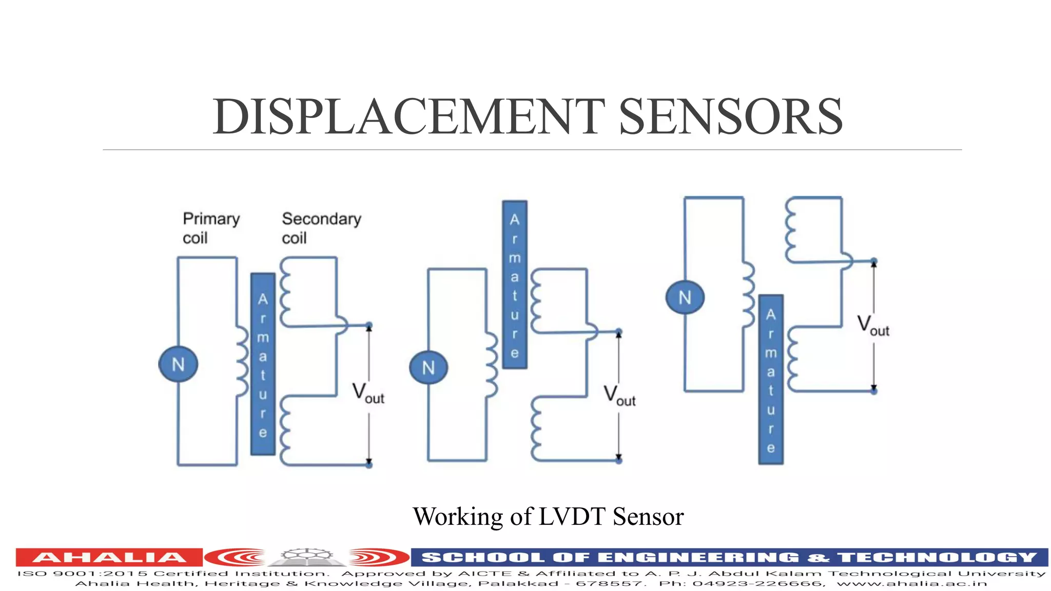
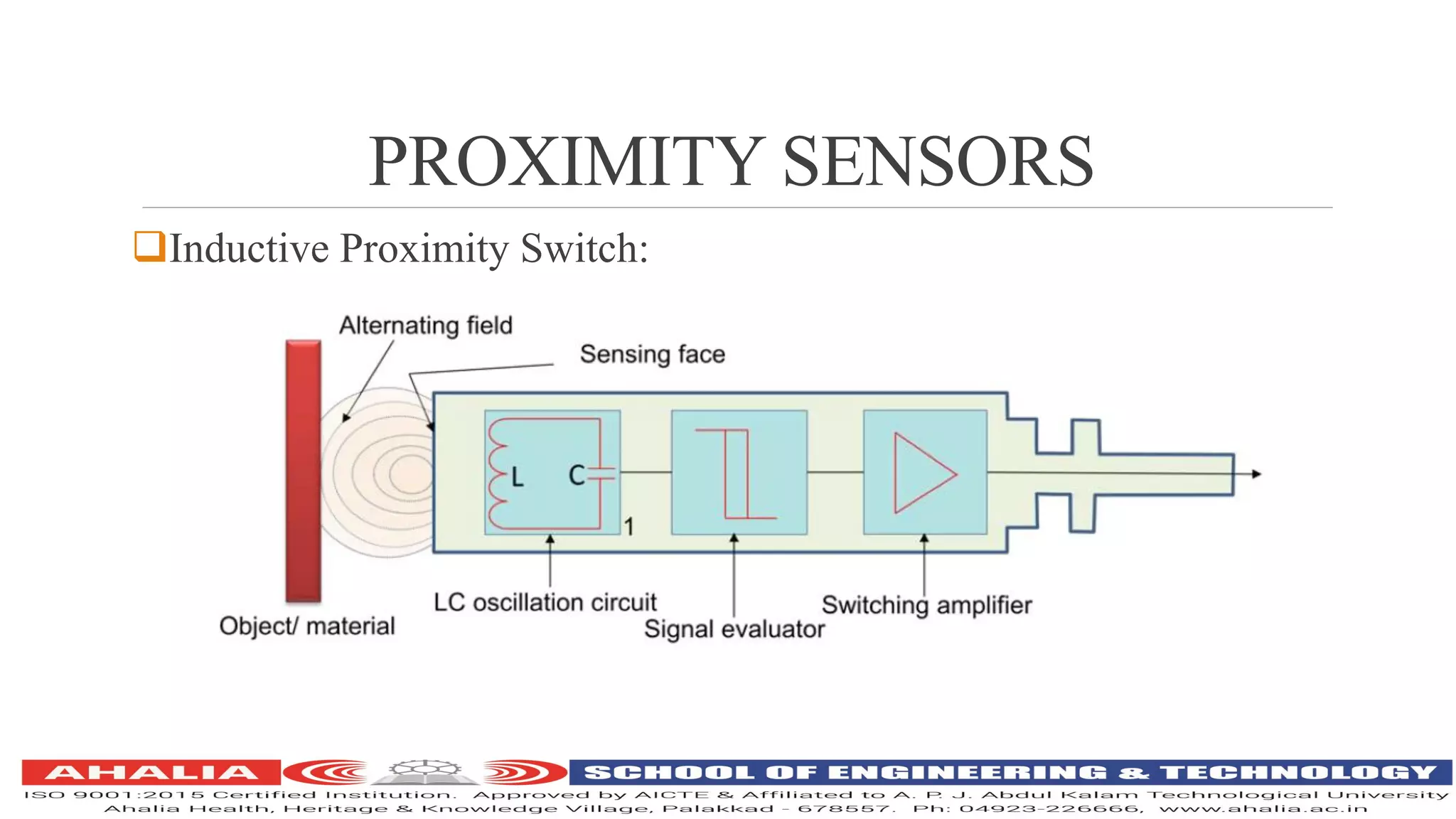
ME 407
MECHATRONICS
DHANESH S
ASSISTANT PROFESSOR-MECHANICAL ENGINEERING
DISPLACEMENT,PROXIMITYAND,
POSITION SENSORS
Displacement Sensor-used to measure amount by which some object has been moved
Position Sensor-Used to determine position of some object with reference to some
reference point
Proximity Sensor-Uses to trace when an object has moved in particular critical distance
of a transducer
Displacement Sensors can be: Potentiometer, Resistant Strain Gauge, LVDT, Push Pull
Displacement Sensor
Positions Sensors can be: photo electric sensors, Hall effect sensors, Optical Encoders
Proximity Sensors can be: Pneumatic Proximity Sensor, Eddy current proximity sensor,
Inductive proximity sensor, Micro switch and Reed Swtich
DISPLACEMENT,PROXIMITYAND,
POSITION SENSORS
Displacement and Positions sensors: classified into
Contact Sensors
Non-Contact Sensors
Contact Senors:
Measured object is in mechanical contact with the sensor
A sensing shaft which is in direct contact with object being monitored
Movement of shaft used to make change in electrical voltage, capacitance or
resistance
Non-Contact Sensors:
Measured object causing change in air pressure in the sensor or a change in
inductance or capacitance. No physical contact between measured object and sensor
DISPLACEMENT,PROXIMITYAND,
POSITION SENSORS
Factors considered while selecting sensors for this applications :
Accuracy required
Resolution required
Size of the displacement
Displacement type
Cost and material made
DISPLACEMENT SENSORS
Potentiometer Sensors:
Potentiometer-used to convert rotary or linear displacement to a voltage
Two types: Rotary potentiometer and Linear Potentiometer
Potentiometer consist of resistance element with a sliding contact that can be mover
from one end to other.
This sliding contact is called Wiper
Motion of sliding contact may be linear or angular
Linear wire wound potentiometer: consist of resistance element with number of turns
of wire wound around a non conducting former together with a movable contact which
travels over bare wires
DISPLACEMENT SENSORS
Linear or angular displacement of wiper contact is directly proportional to input
voltage
Rotary potentiometer: consist of a circular wire-wound track over which a
rotatable sliding contact can be rotated
Wire wound track-can be single turn of helical turn
Object of whose displacement is to be measure is connect to slider by using:
A rotating shaft for angular displacement
A moving rod for linear displacement
A cable that is kept stretched during operation
DISPLACEMENT SENSORS
Applications:
Used in control systems with a feedback loop to ensure moving member or
component reaches its commanded position
Used on machine tool controls, elevators, automobile throttle controls, injection
moulding machines, printing, spraying, robotics etc
Advantages of Resistance Potentiometer:
Simple and inexpensive
Useful for measurement of large amplitudes of displacement
Electrical efficiency is high
Simple in operation
DISPLACEMENT SENSORS
Strain Gauge
Strain: ratio of change in length to original length
Resistance strain guage: exhibits change is electrical resistance when it is stretched or
strained
When strain gauges subject to strain-resistance R changes and change is resistance is
proportional to strain
G is known as Gauge Factor
DISPLACEMENT SENSORS
G value is between 2 to 4 and resistance are take in order of 100 Ohm
Strain gauges: two forms, wire and foil
Design of strain gauge is very long in order to give enough nominal resistance
Strain gauges are bonded or cemented directly on to the surface of body or structure
which is examined
Metal wire strain gauges: a wire stretched between two points in insulting material
such as air
Wires may be made of Copper nickel, chrome nickel or nickel iron alloys
About 0.003mm in diameter and gauge factor of 2. Length of wire is 25mm or less
DISPLACEMENT SENSORS
Applications :
Experimental stress analysis and diagnosis of machines and failure analysis
Multi-axial stress fatigue testing, proof testing, residual stress and vibration
measurement, torque measurement, bending and deflection measurement,
compression and tension measurement etc
Used as sensors for machine tools and safety in automotives
Force measurement in tools, hydraulic or pneumatic press and as impact sensor in
aerospace vehicles
DISPLACEMENT SENSORS
Capacitive Element Bases Sensor(Push Pull Displacement Sensor):
Non-contact type sensor and primarily used to measure linear displacements
from few millimetres to hundreds of millimetres
Three plates, with upper pair forming one capacitor and lower pair another
Linear displacement has two forms:
One of the plates is moved by displacement so that plate separation changes
Area of overlap changes due to displacement
DISPLACEMENT SENSORS
Capacitance C of parallel plate is given by
A is are of overlap between two plates and d is the plate separation
When central plate movers near to top plate or bottom one due to movement of
element/workpiece of which displacement is measured, separation in between
plate changes
DISPLACEMENT SENSORS
When C1 and C2 are connected to Wheatstone’s bridge , resulting out of
balance voltage would be proportional to displacement x
Applications:
Small vessel pump control
Grease level monitoring
Level control of liquids
Metrology applications
Assembly line testing
DISPLACEMENT SENSORS
Linear Variable Differential Transformer(LVDT):
Its inductive displacement sensor
Construction of LVDT Sensor
DISPLACEMENT SENSORS
Working of LVDT Sensor
DISPLACEMENT SENSORS
Consist of three coils spaces along an insulated tube
Central coil is primary coil and other two are secondary coils
Secondary coils are connected in series in such a way that their outputs oppose
each other
Magnetic core attached to element of which displacement is to be monitored is
placed inside insulated tube
Alternating voltage input to primary coil result in alternating electromagnetic
forces generated in secondary coils
DISPLACEMENT SENSORS
When magnetic core is centrally places with half portion in each of secondary
coil regions-resultant voltage is zero
If core is displaced more in secondary coil 1 than in coil2-more emf is
generated in one coil i.e.coil 1 than other and there will be resultant voltage form
coils
If magnetic core is displaced, then value of resultant voltage increases in
proportion with displacement
Signal process devices like low pass filters, demodulators, can be measured by
LVDT sensors
DISPLACEMENT SENSORS
Have good repeatability and reproducibility
Highly reliable
Applications:
Provide displacement feedback for hydraulic cylinders
Control weight and thickness of medicinal products
Automatic inspection of final dimensions of products being packed for dispatch
Measure distance between approaching metals during friction welding process
Monitor fluid level as part of leak detection system
Detect number of currency bills dispensed by an ATM
POSITION SENSORS
Photo-Electric Sensors:
Mostly light emitting diodes for light source and phototransistor is used to
detect light radiation
Two types of photoelectric sensors for sensing objects:
A reflective type photoelectric sensor detects the objects based on reflection of
light onto detector from target
Trasmissive type of sensors is used to measure change in light quantity caused
by targets crossing optical axis
POSITION SENSORS
Hall Effect Sensors:
 When a beam of charged particles passes
through a magnetic field , the beam is
deflected from its straight line path due to
forces acting on the particles. A current
flowing in a conductor, like a beam , is
deflected by a magnetic field.
 This effect is called Hall Effect
POSITIONS SENSORS
Works on the principle that when a beam of charge particles passes through a
magnetic field, forces act on particles and current beam is deflected from its
straight line path
One side of disc will become negatively charged and other side will be positive
charge
This charge separation generates a potential difference which is a measure of
distance of magnetic field from disc carrying current
Have the advantages of being able to operate as switches and it can operate upto
100KHz
POSITION SENSORS
Applications:
Uses a magnetic to electric transducer
Used for measurement of position, displacement and proximity
Used for measurement of current
Used for measurement of power
Measurement of fluid level in a container
Optical Encoder;
Encoder is a device that provides a digital output in response to a linear or
angular displacement
An optical encoder is a suitable transducer for measurement of angular
position and has added advantage of having digital output
POSITION SENSORS
Optical Encoder has four main parts: a light source, a code disk, a light detector
and a signal conditioner
Rotary encoder compose of a glass or plastic code disk with a photographically
deposited radial pattern organized in tracks
Digital encoder is a device that converts motion into a sequence of digital
pulses
Counting or decoding these bits, pulses can be converted into relative or
absolute position measurements
Optical encoders are in rotary or linear configurations
Rotary encoders are two forms: absolute encoder and incremental encoder
POSITION SENSORS
 Widely used in servo motors to
measure rotation of shafts
 Comprises of a disc with three
concentric tracks of equally spaced
holes
 Three light sensors are employed to
detect light passing through holes
 These sensors produce electric pulses
which give angular displacement of
mechanical element e.g.shaft on
which optical encoder is optical
encoder is mounted
POSITION SENSORS
Inner track has just one hole which is used to locate the home position of disc
Hole on middle track offset form holes of outer track by one-half of width of
hole
This arrangement provides direction of rotation to be determines
When disc rotates in clockwise direction, pulses in outer track lead those in
inner, in counter clockwise direction they lag behind
Resolution can be determine by number of holes on disc
POSITION SENSORS
Rotary encoders are two forms:absolute and incremental encoder
Absolute Encoder:
Designed to produce unique digital word corresponding to each rotational position of
shaft that distinguished N distinct positions of the shaft
Eg: if there are 8 tracks, the encoder is capable of producing 256 distinct positions.
Resolution angle of 360/256
Typical absolute encoders may have from 6 to 20 tracks
Each track produces 1 bit of binary numbers according to code that is established by
hole pattern of code disk
POSITION SENSORS
 This is the basic form of absolute
encoder
 Rotating disc has four sensors to
detect light pulses
 Slots are arranged such a way
that outputs made in binary code
 Number of bits in binary number
will be equal to number of tracks
POSITIONS SENSORS
 Most common types of numerical
encoding uses are gray and natural
binary codes
 Track pattern for simple 4track
encoder is shown
POSITION SENSORS
POSITIONS SENSORS
Incremental Encoder:
Produces equally spaced pulses from one or more concentric tracks of code disk
Each track has its own light beam
Thus an encoder with 3 tracks will have three light sources and three light sensors
POSITION SENSORS
Consist of a pair of opaque discs and has a pattern of windows, one of which is fixed
and other is rotating
Rotating disc is attached to shaft whose angular speed is measured
Fixed disc has only one window and a beam of optical light perhaps a LED which
passes through all the time
Second disk has a track of windows cut into which are spaced equidistantly around
second disc
When disc rotates, then a light beam is alternatively transmitted and stopped and so a
pulsed output is produced and detected by photocells and fed to a counter
Number of pulses is proportional to angle through which disc is rotated, resolution
proportional to number of slots on a disc
PROXIMITY SENSORS
Pilot devices used to detect presence of an object without making any physical
contact
Solid state electronic devices, normally of eddy current type or inductive,
capacitive type
Proximity tells central system whether moving part is at a certain place
They come under non contact type sensors
PROXIMITY SENSORS
 Eddy Current Proximity Sensors:
PROXIMITY SENSORS
Used to detect non-magnetic but conductive materials
Comprise of a coil, an oscillator, a detector and a triggering circuit
When an AC current passed through this coil, an alternative magnetic field is generated
If a metal object comes in close proximity of coil, then eddy currents are induced in
object due to magnetic field
These eddy currents create their own magnetic field which distorts magnetic field
responsible for generation
As a result, impedence of coil changes and so amplitude of AC
Can be used to trigger a swtich at some pre-determined level of change in current
Available in small in size, highly reliable and have high sensitivity for small
displacements
PROXIMITY SENSORS
Applications:
Automation requiring precise location
Machine tool monitoring
Final assembly of precision equipment such as disk drives
Measuring dynamics of continuously moving target such as vibrating element
Drive shaft monitoring
Vibration measurements
PROXIMITY SENSORS
Inductive Proximity Switch:
PROXIMITY SENSORS
Used for detection of metallic objects
Has four components:the coil, oscillator, detection circuit and output circuit
AC current is supplied to coil which generates a magnetic field
When a metal object comes closer to end of coil, inductance of coils changes
This is continuously monitored by a circuit which triggers a switch when a
preset value of inductance change is occurred
Applications:
Industrial automation
Security: detection of metal objects, arms, land mines
PROXIMITY SENSORS
Capacitive Sensor:
A device actuated by both conductive and non-conductive materials
Pair of plates of a capacitor is separated by some distance
Depending upon the separation, the capacitance measured will be changed
Proximity of object can be detected if one of plates of capacitor acts as switch
and other being metal object whose proximity is to be detected
PROXIMITY SENSORS
Pneumatic Proximity Sensor:
PROXIMITY SENSORS
Low-pressure air is allowed to escape through a port which is placed in front
position of sensor
Escaping air reduces pressure in nearby sensor output port which there is not
close by object
If there is a close by object the air will not escape readily, so pressure increases
in sensor output port
This output from sensor depends on proximity of objects
PROXIMITY SENSORS
Microswitch and Reed Switch:
PROXIMITY SENSORS
Microswitch is used for determine presence of an item on a conveyer belt
This might be actuated by weight of the item on belt depressing the belt by
spring loaded platform neared to sensor the presence of item in conveyer is
determined
Closeness of switch is done by movement of this spring loaded platform
Reedswitch is a non-contact proximity switch used for checking closure of
doors
Consist of two magnetic switch contacts sealed in glass tube
When a magnet is brought close to the switch, magnetic reed are attracted each
other and close the switch contacts

Me 407 mechatronics ppt 2

  • 1.
    ME 407 MECHATRONICS DHANESH S ASSISTANTPROFESSOR-MECHANICAL ENGINEERING
  • 2.
    DISPLACEMENT,PROXIMITYAND, POSITION SENSORS Displacement Sensor-usedto measure amount by which some object has been moved Position Sensor-Used to determine position of some object with reference to some reference point Proximity Sensor-Uses to trace when an object has moved in particular critical distance of a transducer Displacement Sensors can be: Potentiometer, Resistant Strain Gauge, LVDT, Push Pull Displacement Sensor Positions Sensors can be: photo electric sensors, Hall effect sensors, Optical Encoders Proximity Sensors can be: Pneumatic Proximity Sensor, Eddy current proximity sensor, Inductive proximity sensor, Micro switch and Reed Swtich
  • 3.
    DISPLACEMENT,PROXIMITYAND, POSITION SENSORS Displacement andPositions sensors: classified into Contact Sensors Non-Contact Sensors Contact Senors: Measured object is in mechanical contact with the sensor A sensing shaft which is in direct contact with object being monitored Movement of shaft used to make change in electrical voltage, capacitance or resistance Non-Contact Sensors: Measured object causing change in air pressure in the sensor or a change in inductance or capacitance. No physical contact between measured object and sensor
  • 4.
    DISPLACEMENT,PROXIMITYAND, POSITION SENSORS Factors consideredwhile selecting sensors for this applications : Accuracy required Resolution required Size of the displacement Displacement type Cost and material made
  • 5.
    DISPLACEMENT SENSORS Potentiometer Sensors: Potentiometer-usedto convert rotary or linear displacement to a voltage Two types: Rotary potentiometer and Linear Potentiometer Potentiometer consist of resistance element with a sliding contact that can be mover from one end to other. This sliding contact is called Wiper Motion of sliding contact may be linear or angular Linear wire wound potentiometer: consist of resistance element with number of turns of wire wound around a non conducting former together with a movable contact which travels over bare wires
  • 6.
    DISPLACEMENT SENSORS Linear orangular displacement of wiper contact is directly proportional to input voltage Rotary potentiometer: consist of a circular wire-wound track over which a rotatable sliding contact can be rotated Wire wound track-can be single turn of helical turn Object of whose displacement is to be measure is connect to slider by using: A rotating shaft for angular displacement A moving rod for linear displacement A cable that is kept stretched during operation
  • 7.
  • 8.
  • 9.
  • 10.
    DISPLACEMENT SENSORS Applications: Used incontrol systems with a feedback loop to ensure moving member or component reaches its commanded position Used on machine tool controls, elevators, automobile throttle controls, injection moulding machines, printing, spraying, robotics etc Advantages of Resistance Potentiometer: Simple and inexpensive Useful for measurement of large amplitudes of displacement Electrical efficiency is high Simple in operation
  • 11.
    DISPLACEMENT SENSORS Strain Gauge Strain:ratio of change in length to original length Resistance strain guage: exhibits change is electrical resistance when it is stretched or strained When strain gauges subject to strain-resistance R changes and change is resistance is proportional to strain G is known as Gauge Factor
  • 12.
    DISPLACEMENT SENSORS G valueis between 2 to 4 and resistance are take in order of 100 Ohm Strain gauges: two forms, wire and foil Design of strain gauge is very long in order to give enough nominal resistance Strain gauges are bonded or cemented directly on to the surface of body or structure which is examined Metal wire strain gauges: a wire stretched between two points in insulting material such as air Wires may be made of Copper nickel, chrome nickel or nickel iron alloys About 0.003mm in diameter and gauge factor of 2. Length of wire is 25mm or less
  • 13.
  • 14.
  • 15.
  • 16.
    DISPLACEMENT SENSORS Applications : Experimentalstress analysis and diagnosis of machines and failure analysis Multi-axial stress fatigue testing, proof testing, residual stress and vibration measurement, torque measurement, bending and deflection measurement, compression and tension measurement etc Used as sensors for machine tools and safety in automotives Force measurement in tools, hydraulic or pneumatic press and as impact sensor in aerospace vehicles
  • 17.
    DISPLACEMENT SENSORS Capacitive ElementBases Sensor(Push Pull Displacement Sensor): Non-contact type sensor and primarily used to measure linear displacements from few millimetres to hundreds of millimetres Three plates, with upper pair forming one capacitor and lower pair another Linear displacement has two forms: One of the plates is moved by displacement so that plate separation changes Area of overlap changes due to displacement
  • 18.
  • 19.
    DISPLACEMENT SENSORS Capacitance Cof parallel plate is given by A is are of overlap between two plates and d is the plate separation When central plate movers near to top plate or bottom one due to movement of element/workpiece of which displacement is measured, separation in between plate changes
  • 20.
    DISPLACEMENT SENSORS When C1and C2 are connected to Wheatstone’s bridge , resulting out of balance voltage would be proportional to displacement x Applications: Small vessel pump control Grease level monitoring Level control of liquids Metrology applications Assembly line testing
  • 21.
    DISPLACEMENT SENSORS Linear VariableDifferential Transformer(LVDT): Its inductive displacement sensor Construction of LVDT Sensor
  • 22.
  • 23.
    DISPLACEMENT SENSORS Consist ofthree coils spaces along an insulated tube Central coil is primary coil and other two are secondary coils Secondary coils are connected in series in such a way that their outputs oppose each other Magnetic core attached to element of which displacement is to be monitored is placed inside insulated tube Alternating voltage input to primary coil result in alternating electromagnetic forces generated in secondary coils
  • 24.
    DISPLACEMENT SENSORS When magneticcore is centrally places with half portion in each of secondary coil regions-resultant voltage is zero If core is displaced more in secondary coil 1 than in coil2-more emf is generated in one coil i.e.coil 1 than other and there will be resultant voltage form coils If magnetic core is displaced, then value of resultant voltage increases in proportion with displacement Signal process devices like low pass filters, demodulators, can be measured by LVDT sensors
  • 25.
    DISPLACEMENT SENSORS Have goodrepeatability and reproducibility Highly reliable Applications: Provide displacement feedback for hydraulic cylinders Control weight and thickness of medicinal products Automatic inspection of final dimensions of products being packed for dispatch Measure distance between approaching metals during friction welding process Monitor fluid level as part of leak detection system Detect number of currency bills dispensed by an ATM
  • 26.
    POSITION SENSORS Photo-Electric Sensors: Mostlylight emitting diodes for light source and phototransistor is used to detect light radiation Two types of photoelectric sensors for sensing objects: A reflective type photoelectric sensor detects the objects based on reflection of light onto detector from target Trasmissive type of sensors is used to measure change in light quantity caused by targets crossing optical axis
  • 27.
    POSITION SENSORS Hall EffectSensors:  When a beam of charged particles passes through a magnetic field , the beam is deflected from its straight line path due to forces acting on the particles. A current flowing in a conductor, like a beam , is deflected by a magnetic field.  This effect is called Hall Effect
  • 28.
    POSITIONS SENSORS Works onthe principle that when a beam of charge particles passes through a magnetic field, forces act on particles and current beam is deflected from its straight line path One side of disc will become negatively charged and other side will be positive charge This charge separation generates a potential difference which is a measure of distance of magnetic field from disc carrying current Have the advantages of being able to operate as switches and it can operate upto 100KHz
  • 29.
    POSITION SENSORS Applications: Uses amagnetic to electric transducer Used for measurement of position, displacement and proximity Used for measurement of current Used for measurement of power Measurement of fluid level in a container Optical Encoder; Encoder is a device that provides a digital output in response to a linear or angular displacement An optical encoder is a suitable transducer for measurement of angular position and has added advantage of having digital output
  • 30.
    POSITION SENSORS Optical Encoderhas four main parts: a light source, a code disk, a light detector and a signal conditioner Rotary encoder compose of a glass or plastic code disk with a photographically deposited radial pattern organized in tracks Digital encoder is a device that converts motion into a sequence of digital pulses Counting or decoding these bits, pulses can be converted into relative or absolute position measurements Optical encoders are in rotary or linear configurations Rotary encoders are two forms: absolute encoder and incremental encoder
  • 31.
    POSITION SENSORS  Widelyused in servo motors to measure rotation of shafts  Comprises of a disc with three concentric tracks of equally spaced holes  Three light sensors are employed to detect light passing through holes  These sensors produce electric pulses which give angular displacement of mechanical element e.g.shaft on which optical encoder is optical encoder is mounted
  • 32.
    POSITION SENSORS Inner trackhas just one hole which is used to locate the home position of disc Hole on middle track offset form holes of outer track by one-half of width of hole This arrangement provides direction of rotation to be determines When disc rotates in clockwise direction, pulses in outer track lead those in inner, in counter clockwise direction they lag behind Resolution can be determine by number of holes on disc
  • 33.
    POSITION SENSORS Rotary encodersare two forms:absolute and incremental encoder Absolute Encoder: Designed to produce unique digital word corresponding to each rotational position of shaft that distinguished N distinct positions of the shaft Eg: if there are 8 tracks, the encoder is capable of producing 256 distinct positions. Resolution angle of 360/256 Typical absolute encoders may have from 6 to 20 tracks Each track produces 1 bit of binary numbers according to code that is established by hole pattern of code disk
  • 34.
    POSITION SENSORS  Thisis the basic form of absolute encoder  Rotating disc has four sensors to detect light pulses  Slots are arranged such a way that outputs made in binary code  Number of bits in binary number will be equal to number of tracks
  • 35.
    POSITIONS SENSORS  Mostcommon types of numerical encoding uses are gray and natural binary codes  Track pattern for simple 4track encoder is shown
  • 36.
  • 37.
    POSITIONS SENSORS Incremental Encoder: Producesequally spaced pulses from one or more concentric tracks of code disk Each track has its own light beam Thus an encoder with 3 tracks will have three light sources and three light sensors
  • 38.
    POSITION SENSORS Consist ofa pair of opaque discs and has a pattern of windows, one of which is fixed and other is rotating Rotating disc is attached to shaft whose angular speed is measured Fixed disc has only one window and a beam of optical light perhaps a LED which passes through all the time Second disk has a track of windows cut into which are spaced equidistantly around second disc When disc rotates, then a light beam is alternatively transmitted and stopped and so a pulsed output is produced and detected by photocells and fed to a counter Number of pulses is proportional to angle through which disc is rotated, resolution proportional to number of slots on a disc
  • 39.
    PROXIMITY SENSORS Pilot devicesused to detect presence of an object without making any physical contact Solid state electronic devices, normally of eddy current type or inductive, capacitive type Proximity tells central system whether moving part is at a certain place They come under non contact type sensors
  • 40.
    PROXIMITY SENSORS  EddyCurrent Proximity Sensors:
  • 41.
    PROXIMITY SENSORS Used todetect non-magnetic but conductive materials Comprise of a coil, an oscillator, a detector and a triggering circuit When an AC current passed through this coil, an alternative magnetic field is generated If a metal object comes in close proximity of coil, then eddy currents are induced in object due to magnetic field These eddy currents create their own magnetic field which distorts magnetic field responsible for generation As a result, impedence of coil changes and so amplitude of AC Can be used to trigger a swtich at some pre-determined level of change in current Available in small in size, highly reliable and have high sensitivity for small displacements
  • 42.
    PROXIMITY SENSORS Applications: Automation requiringprecise location Machine tool monitoring Final assembly of precision equipment such as disk drives Measuring dynamics of continuously moving target such as vibrating element Drive shaft monitoring Vibration measurements
  • 43.
  • 44.
    PROXIMITY SENSORS Used fordetection of metallic objects Has four components:the coil, oscillator, detection circuit and output circuit AC current is supplied to coil which generates a magnetic field When a metal object comes closer to end of coil, inductance of coils changes This is continuously monitored by a circuit which triggers a switch when a preset value of inductance change is occurred Applications: Industrial automation Security: detection of metal objects, arms, land mines
  • 45.
    PROXIMITY SENSORS Capacitive Sensor: Adevice actuated by both conductive and non-conductive materials Pair of plates of a capacitor is separated by some distance Depending upon the separation, the capacitance measured will be changed Proximity of object can be detected if one of plates of capacitor acts as switch and other being metal object whose proximity is to be detected
  • 46.
  • 47.
    PROXIMITY SENSORS Low-pressure airis allowed to escape through a port which is placed in front position of sensor Escaping air reduces pressure in nearby sensor output port which there is not close by object If there is a close by object the air will not escape readily, so pressure increases in sensor output port This output from sensor depends on proximity of objects
  • 48.
  • 49.
    PROXIMITY SENSORS Microswitch isused for determine presence of an item on a conveyer belt This might be actuated by weight of the item on belt depressing the belt by spring loaded platform neared to sensor the presence of item in conveyer is determined Closeness of switch is done by movement of this spring loaded platform Reedswitch is a non-contact proximity switch used for checking closure of doors Consist of two magnetic switch contacts sealed in glass tube When a magnet is brought close to the switch, magnetic reed are attracted each other and close the switch contacts