
Recommended
More Related Content
What's hot
What's hot (19)
Similar to Autonomous Sumo Bot Wildcat Design and Software
Similar to Autonomous Sumo Bot Wildcat Design and Software (20)
Recently uploaded
Recently uploaded (20)
Autonomous Sumo Bot Wildcat Design and Software
- 1. Wildcat: An Autonomous Sumo Bot To: Charlie Refvem, Lecturer, Department of Mechanical Engineering, Cal Poly SLO crefvem@calpoly.edu From: Darya Darvish Spencer Goodman ddarvish@calpoly.edu slgoodma@calpoly.edu Date: 3/16/2020 RE: ME 405 Final Project Report
- 2. Index Appendices, 17 Design Development Hardware Design, 4 Software Design, 8 Introduction, 2 Results, 16 Software Design, 7 Specifications, 3
- 3. Introduction The goal of this project was to build an autonomous sumo bot whose goal is to detect and enemy bot and push them outside of the sumo ring. We were tasked to design and develop the hardware and software for the robot, as well as select the appropriate purchased parts to use in order to make our bot functional. We decided to design the chassis of our robot from scratch and 3D print it, and we also bought a robot kit from amazon which contained sensors and other hardware that we were able to integrate into our chassis. The reason behind 3D printing the robot is that we wanted to make our robot as unique as possible, and we also wanted to gain experience designing and working with 3D printed parts. In order to keep our robot relatively simple in terms of actuation, we decided to use two DC motors equipped with encoders in order to drive our robot. This way, the robot can turn if one of the wheels is spinning faster than the other, or move straight forward and back. Other sensors that we integrated into our robot are an ultrasonic sensor, line detecting sensor, wheel encoders that were built into the motors, and IR sensor. Finally, we developed a set of tasks and states in order for the robot to take in data from sensors, process this data, and make decisions on what to do in order to act in an optimal fashion. Our robot was finally tested during the final day of competition in a battle against all the other robots in the class. This report dives deeper into the in design for both hardware and software, as well as discusses the results of our project.
- 4. Specifications Weight 1.5 lbf Footprint 7.5 x 7.75 inches Height 5 inches Main Battery Capacity 8.14 Wh Nominal Battery Voltage 11.1 V Motor Power 1.464 W Top Speed 1.31 ft/s Calculations for nominal battery voltage, motor power, and top speed can be found in Appendix A.
- 5. Design Development Hardware Design: The primary hardware components of our bot were obtained from the OSOYOO Model 3 Robot Car DIY Starter Kit shown in Appendix B. Since we didn’t need all of the equipment that came from the kit, we only utilized the line tracking sensor, Ultrasonic position reading sensor, the wheels, and all of the fasteners and wires that came with the kit. The chassis that came with the kit was too large for our dimensions, so we instead used the chassis to figure out where we needed to place each component of our sumo bot, and then designed the 3D-model in Figure 1 below around the size of each component and their placements. This design also accommodated for the size of the ME 405 Microcontroller, as well as the 3S 30C Lipo Battery shown in Appendix B. Figure 1. 3D-Model of our sumobot. The rectangular trenches in the top of the chassis were designed to hold the motors shown in Appendix B. We ordered motors with a high maximum speed (1.31 ft/s) and low torque (0.95 kg-cm) in order to be able to evade other bots and then use momentum to drive them off the board. Further calculations for the motor specifications can be found in Appendix B. Once we had our 3D-model completed, we visited the Design Innovations Lab and had it 3D printed. A lot of volume was cut out in order to reduce the cost of the print, but the structure was still sturdy enough to withstand any hits and also prevent our hardware from being exposed. After the 3D print was complete, we needed to drill all of the holes needed for each component in order to fasten them to the board at their proper locations. Figures 2 and 3 below are from a SolidWorks sketch of the bot that specifies the dimensions of the bot frame, as well as shows each location of the holes we eventually drilled into the board.
- 6. Figure 2. Top view and dimensions of the sumo bot. Figure 3. Side view and dimensions of the sumo bot. After drilling the holes, we decided to spray paint the bot black since it would be harder for opponents to detect our bot with infrared signals if our bot was colored black rather than white. Once the paint dried and the electronic components were fastened to the board, the last components we needed were a charger for the microcontroller, and an
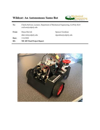
- 7. emergency stop button to cut the power signal from the battery in case the bot drove out of control. To power the microcontroller, we used a standard portable phone charger, and the emergency stop button was acquired as a spare part from another team. Figure 4 shows the fully assembled Wildcat Sumobot. Figure 4. Fully assembled Wildcat Sumobot. The total cost of the hardware for this project was $177.21 as seen in our bill of materials in Appendix C. About half of that cost came from having the frame 3D-Printed since the 3D printing cost $5 per cubic inch, which also included the volume of the required support material. We could have used one of the free 3D printers on campus instead, but it would’ve taken a lot longer to get our frame completed and we wanted to have it ready sooner rather than later to get more testing completed.
- 8. Software Design: The main file that our robot runs consists of a set of tasks that are run by a scheduler that was created by Dr. Ridgley. In the main functions, shares and queues are initialized that run the different tasks that are used by our robot. Each task is set up in order to run at a certain timing period and priority, and the scheduler created by Dr. Ridgely is responsible for running each task at the appropriate time. The tasks that our robot runs consists of a perception task, and IR sensor task, a motion control task, and a motor control task. In this report, the different programs will be described in terms of their purpose and methods of design. The first program that will be analyzed is the IR sensor task, which is used to start and stop the robot. The IR sensor task uses a timer channel to generate interrupts during rising and falling edges. The timer counter value is recorded during each time an interrupt is generated, and from this it is possible to decode an messaged by using the NEC infrared protocol. The interrupt is called an interrupt callback function, which then stores the timer counter values into a queue which is then decoded by the IR sensors task when the queue is full. If the decoded value corresponds to a 1 pressed on the IR remote, the robot will start, and if the decoded value corresponds to a 0 pressed on the IR remote, the robot will then proceed to stop all motor actions. Below is a snippet of code that first initializes the IR sensor by setting up a timer. charmander = pyb.Pin (pyb.Pin.board.PA8, pyb.Pin.IN) pokemon = pyb.Timer(1, period = 0xFFFF, prescaler = 79) channel_1 = pokemon.channel(1, mode = pyb.Timer.IC, polarity = pyb.Timer.BOTH, pin=charmander) channel_1.callback(interrupt) ir_time_queue = Queue("I", 68) ir_full_flag = Share("i") ir_full_flag.put(0, in_ISR = True) Figure 5. Initializing IR Sensor Code. When a button is pressed by the IR remote, this causes the timer to generate interrupts. From here, the interrupt callback function is called which stores the values of the counter in a queue. Figure 6 shows the interrupt callback function.
- 9. def interrupt(pokemon): '''Interrupt subroutine that allows the IR sensor to read the infrared signal from the remote controller.''' if not ir_time_queue.full() and not ir_full_flag.get(): # time_queue = Queue("I", 68) ir_time_queue.put(pokemon.counter(), in_ISR=True) else: ir_full_flag.put(1) Figure 6. Interrupt Callback Function If the queue is full, then the interrupt callback function will signal that the queue is fully by putting a 1 into the ir_full_flag, which then triggers the IR sensor task to go into the compute state. Below is a simple state transition diagram and a snippet of code that shows how the IR sensor task works. Figure 7: IR Sensor Task Diagram
- 10. def ir_sensor_task (): while True: if ir_full_flag.get(): # Tell us we have data to analyze delta_t = [] first_val = ir_time_queue.get() #compute difference in time while not ir_time_queue.empty(): second_val = ir_time_queue.get() if second_val-first_val < 0: delta_t.append(second_val-first_val + 65536) else: delta_t.append(second_val - first_val) first_val = second_val if not (8500 < delta_t[0] < 9500) or delta_t[3] > 1000: ir_full_flag.put(False) continue delta_t = delta_t[3:] bool_arr = [] #convert time differences into 1 and 0 … … CMD = code[8:16] if int(CMD, 2) == 22: master_go.put(0) elif int(CMD, 2) == 12: master_go.put(1) ir_full_flag.put(0) Figure 8: IR SensorTask Code By setting the master_go share to 1, this enables all of the other tasks to begin running, so the IR sensor tasks decide whether the robot starts to move or not. Every other task first has a check to see if the master_go flag is set to 1, and if it is not set to 1 then the task will not run. The next task that we will be explaining is the perception task. This task reads in values from our line detecting sensor as well as our ultrasonic sensor. We decided to use these
- 11. two sensors because we found that we wanted to keep our sensor suite limited but also give us enough information in order to make decisions. We found that the line detecting sensor is ideal, because it makes sure that we stop before we leave the sumo ring, and we chose the ultrasonic sensor because it would give us an easy way to detect where the opponent is on the ring. We considered using an IMU, but we chose to limit our sensors to just these two for perceptions so that our system would be simple enough to program and control. The first sensor that we will dive into is our line detecting sensor. There are sub sensors on the sensor chip that can sense a line, one on the left, one on the middle and one on the right. This sensor chip has three output pins that were set up to go into our microcontroller, and these pins will output high if they do not detect a line and output low if they do detect a line. The code that was written in order to set up and read the sensor is shown below. class LineTracker: ''' This class implements a line tracking sensor. ''' def __init__ (self, pin_1, pin_2, pin_3): ''' Creates a motor driver by initializing GPIO pins and turning the motor off for safety. ''' #print('Creating a motor driver') self.pin1 = pyb.Pin (pin_1, pyb.Pin.IN) self.pin2 = pyb.Pin (pin_2, pyb.Pin.IN) self.pin3 = pyb.Pin (pin_3, pyb.Pin.IN) def read_L(self): return self.pin1.value() def read_C(self): return self.pin2.value() def read_R(self): return self.pin3.value() Figure 8: Linetracker Class Code The read_L, read_C, and read_R methods are called by the perception task and each of the values returned is stored into a respective share that is then accessed by other states. The next sensor that will be described is the ultrasonic sensor. The ultrasonic sensor works by sending out a short pulse of sound at high frequency, recording the time that it was sent, and then recording the time that the pulse was received. By taking the difference in time, it is possible to calculate how far away the object was from you by
- 12. using the speed of sound and backcalculation distance. The code to use the ultrasonic sensor was found on Github by user Roberto Sánchez using the Apache License 2.0. https://www.apache.org/licenses/LICENSE-2.0". The final task is shown below, which reads the data from both of the sensors and stores them in shares so that other tasks can access them. The tasks consist of two simple states, which involve waiting for the master_go share to be set to 1 or reading sensor values and setting shares. We decided to create shares to hold the value of the ultrasonic sensor, left, center, and right line detecting sensors, as well as set up our motion planning shares. Figure 9: Perception Task State Transition Diagram
- 13. def perception (): #initialize US sensor bro = ultrasonic.UltraSonic("PA9", "PB10") liner = linetracker.LineTracker(pyb.Pin.board.PB8, pyb.Pin.board.PB9, pyb.Pin.board.PB3) while True: if master_go.get(): enemy_position.put(bro.distance_cm()) #print(bro.distance_cm()) Line_L.put(liner.read_L()) Line_C.put(liner.read_C()) Line_R.put(liner.read_R()) #Initialized when IR signal is read. if retreating.get(): #Wait for retreat to finish. yield(0) if Line_L.get() and Line_C.get() and Line_R.get(): #No line has been sensed. if enemy_position.get() > 15: #Checks if enemy is near or far. scan.put(1) attack.put(0) else: attack.put(1) scan.put(0) retreat.put(0) else: #Retreat if line has been sensed. scan.put(0) retreat.put(1) yield(0) Figure 10: Perception Task Code Our motion planning shares that this task can set are as follows. The scan share tells the robot to search for the opponent, and retreat share says to fall back since it has detected a line, and attack says to charge if an opponent has been sensed. These shares are used by the motion control tasks which is the next task that we will be analyzing.
- 14. The motion control task works by analyzing the scan share, retreating share, and as well as the ready_left, and ready_right share. This task sets the left_pos and right_pos shares which tell the motor task where to move each motor. The idea behind this design is that one task can calculate the setpoints of each motor, and this way it is easier for the user to program and think about how the robot is thinking and acting. When the robot is in any of the scan states, it will turn left, move straight, turn right, move straight, and then repeat these maneuvers until the state is changed to a different one. It will only transition to another state if the ready_left and ready_right flag are set, which indicates that the robot has completed the previously planned maneuver and the motors have reached their setpoint. If the robot is in the retreating state but either of the wheels are ready, it will then transition out of that state into the scan state. The state transition diagram is shown below. Figure 11: Motion Control State Transition Diagram
- 15. The final task that our motor runs is the motor control task. This is the most complicated task, because it does the most amount of things and has the most amount of computation. It uses the motor class, encoder class, and controller class in order to set up both motors, both encoders, and control each motor. While this task only has three different states, within each state a number of computations is done to figure out where the robot should go. For example, a snippet of the retreating state is shown below. The code calculated which direction the robot should move depends on which one of the line sensors was triggered. if not Line_L.get() and not Line_C.get() and not Line_R.get(): ready_left.put(0) ready_right.put(0) time_elapsed.put(time.time()) left_pos.put(cosmo.read()-200) right_pos.put(enc.read()+200) retreat.put(0) retreating.put(1) elif not Line_L.get() and Line_R.get(): ready_left.put(0) ready_right.put(0) time_elapsed.put(time.time()) left_pos.put(cosmo.read()-450) right_pos.put(enc.read()-130) retreat.put(0) retreating.put(1) Figure 12: Motion Control Task Code Snippit The motor control task always runs code that uses the left_pos and right_pos shares in order to calculate a new setpoint similar to the code written in Lab 2. It also runs a section of code that sets the ready_right and ready_left shares to 1 if the motor has reached the desired position. Integral control was also added to our controller class, so this will help when the robot gets stuck in order to build up a larger total error value. The state transition diagram is shown below.
- 16. Figure 12: Motor State Transition Diagram By combining these four tasks, we have all the tasks needed to run our robot. The timing requirements and priority were chosen based on which task is more important to run, and they were also tuned by testing our robot out to see if our robot could react and respond in time. The complete task diagram is shown below.
- 17. Figure 13: Robot Task Diagram
- 18. Results While our robot worked very well in terms of sensing its surroundings, making decisions, and computing desired motor set points during testing, we ran into issues when we put our robot out into the sumo field. The first issue is that our motor was not powerful enough to move our bot at low duty cycle. This meant that in order to move our robot, we had to use a high proportional gain in our motor controller, and since we were using positional control sometimes the robot would not be able to get to the desired positions since when the error becomes very small, the duty cycle is also very small. Since small duty cycles are not able to move our robot, we decided to add integral control to our robot, and this helped by getting the robot to move when it was stuck after a few seconds. This helped in certain scenarios, but we ran into another issue because when the robot outputs a high duty cycle, the wheels spin very fast and lose traction on the sumo ring. We tried adding high friction tape to our wheels, but in the end our motors were still unable to move our bot because of their low torque output. In the future, we should have done more calculations in order to better choose motors to drive our robot, since this was the only major drawback that our motor had. Other than this, our robot did exactly what we wanted it to do. The IR sensor works most of the time, and we are able to successfully start and stop our motor when we want to. Our tasks were set up well, and our robot was able to quickly sense when it had reached an edge and immediately backed up. Both of our sensors gave us enough information so that we could act, and our robot was able to output maximum power when it saw an opponent in front of it. Overall, this was a great project that made us learn a lot about programming, sensors, and robot design, and it was also very fun.
- 19. Appendices Appendix A - Design Specifications Calculations Appendix B - Hardware Figures Appendix C - Bill of Materials
- 20. Appendix A - Design Specifications Calculations
- 21. Appendix B - Hardware Figures Figure 1. OSOYOO Model Robot Car kit. Figure 2. 150 RPM DC Motor (with encoder) dimensions.
- 22. Figure 3. HRB 11.1V 3S 30C Lipo Battery.
- 23. Appendix C - Bill of Materials Material Quantity Cost Location Purchased OSOYOO 3D Model Car Kit 1 $38.46 Amazon 150RPM DC Motor with Encoder 2 $29.76 Amazon 11.1V 3S 30C Lipo Battery 1 $20.99 Amazon 3D Print Bot Frame 1 $88.00 Digital Fabrications Lab TOTAL COST: $177.21