Download as PDF, PPTX


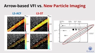
![17
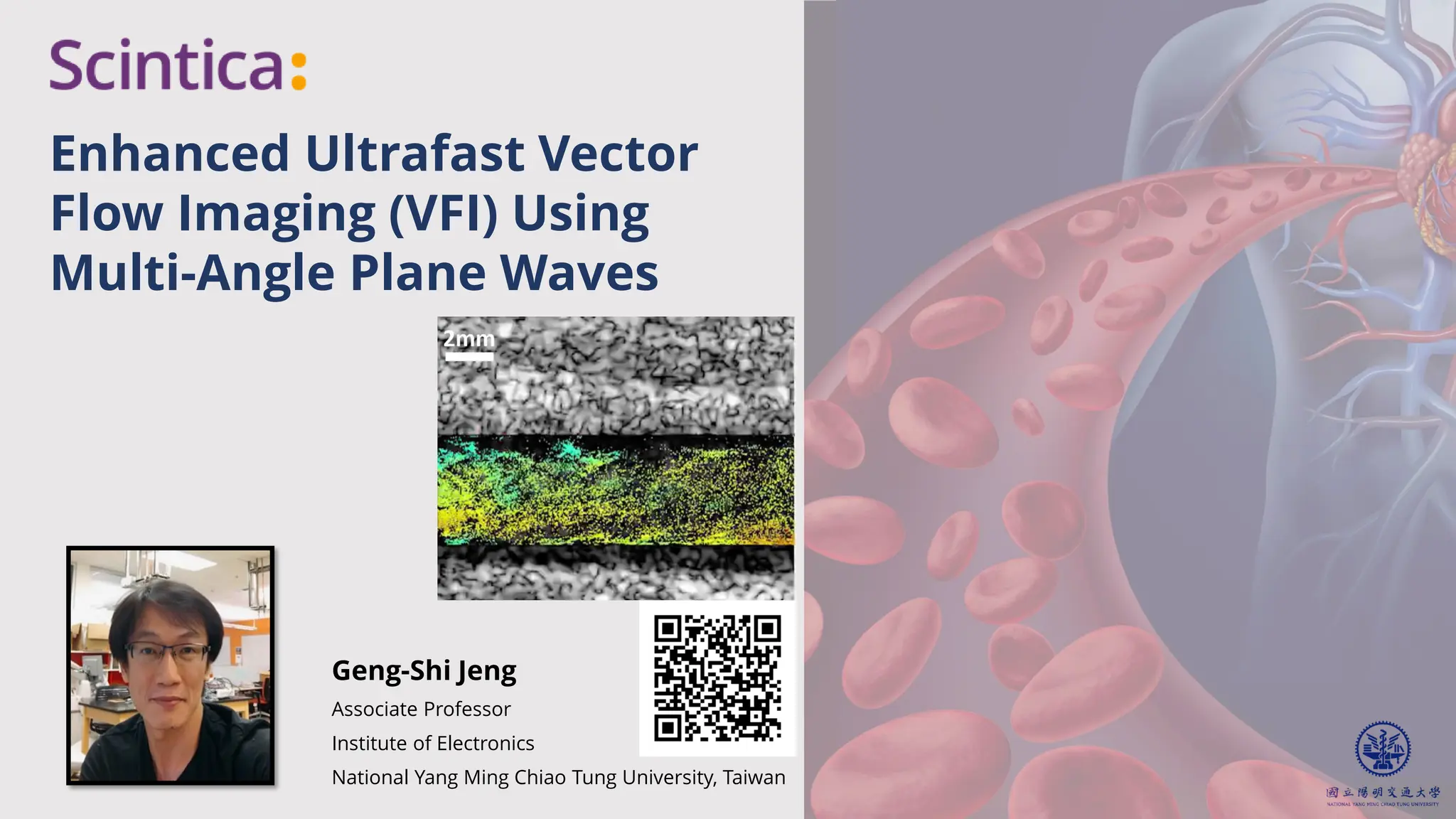
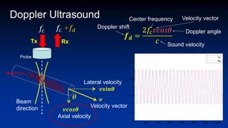
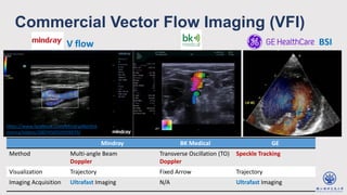
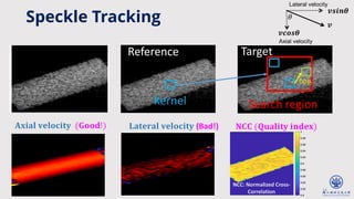
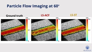
Laminar flow
v r = 𝑣0[1 −
𝑟
𝑅
2
]
Parameter Value
Number of Tx/Rx channels 128
Array pitch 0.2 mm
Sampling rate 32 MHz
Center frequency 8 MHz
Plane wave angle −𝟖𝒐, 𝟎𝒐, 𝟖𝒐
Pulse repetition frequency 10 kHz
Radius of blood vessel (R) 4 mm
Peak flow velocity (𝒗𝟎) 0.2 m/s
Ensemble size 10
Simulation (Field II)](https://image.slidesharecdn.com/vfiwebinarfinal1-240509184849-b68a1482/85/May-9-2024-Enhanced-Ultrafast-Vector-Flow-Imaging-VFI-Using-Multi-Angle-Plane-Waves-17-320.jpg)
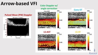
![20
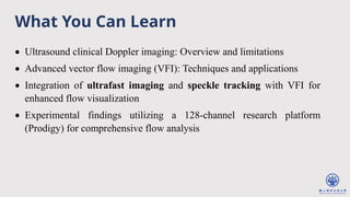
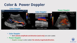
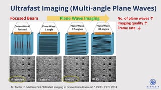
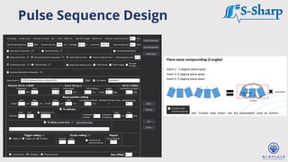
Parameter Vessel 𝜽 = 𝟗𝟎𝒐 Vessel 𝜽 = 𝟓𝟓𝒐
Array element 128 128
Array pitch 0.2 mm 0.2 mm
Sampling rate 32 MHz 32 MHz
Center frequency 8 MHz 6 MHz
Pulse repetition
frequency
10 kHz 9 kHz
Ensemble size 10 10
Plane wave angle [−16o
, 0o
, 16o
] [16o
, −8o
, 0o
, 8o
, 16o
]
Source: https://jdigitaldiagnostics.com/DD/article/view/76511#tabs-5
Source: https://www.s-sharp.com/uploads/
root//Prodigy256system20201126.jpg
in vitro Experiments
Vessel 𝜽 = 𝟓𝟓𝒐
Vessel 𝜽 = 𝟗𝟎𝒐](https://image.slidesharecdn.com/vfiwebinarfinal1-240509184849-b68a1482/85/May-9-2024-Enhanced-Ultrafast-Vector-Flow-Imaging-VFI-Using-Multi-Angle-Plane-Waves-20-320.jpg)
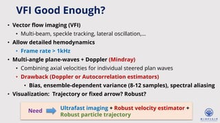
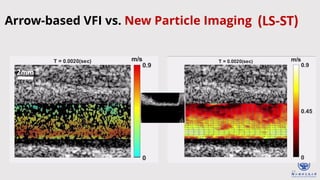
![25
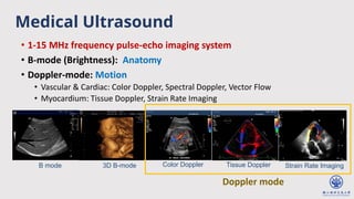
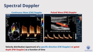
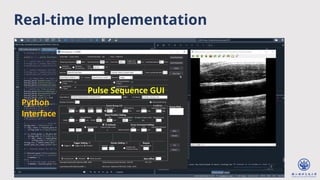
Parameter Value
Number of Tx/Rx channels 128
Array pitch 0.2 mm
Sampling rate 32 MHz
Center frequency 8 MHz
Pulse repetition frequency 12 kHz
Ensemble size 10
Plane wave angle [−16o
, 0o
, 16o
]
Source: https://www.docknet.jp/media/medical-checkup-23/
in vivo Experiments
Carotid arteries were measured](https://image.slidesharecdn.com/vfiwebinarfinal1-240509184849-b68a1482/85/May-9-2024-Enhanced-Ultrafast-Vector-Flow-Imaging-VFI-Using-Multi-Angle-Plane-Waves-25-320.jpg)
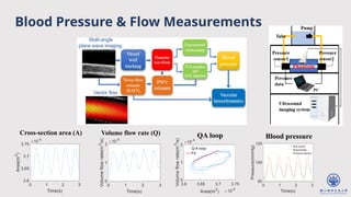


The document discusses enhanced ultrafast vector flow imaging (VFI) using multi-angle plane waves and its applications in medical ultrasound, particularly in hemodynamics visualization. It outlines various techniques and technologies, including speckle tracking, and provides experimental findings using a 128-channel research platform called Prodigy. The conclusion highlights the advantages of VFI over conventional Doppler imaging for comprehensive flow analysis and the integration of advanced imaging methods for improved results.


![Doppler principles [2]](https://cdn.slidesharecdn.com/ss_thumbnails/dopplerprinciples2-210517111747-thumbnail.jpg?width=640&height=640&fit=bounds)


![谷歌留痕技术 [ 𝙩𝙤𝙥 𝟮𝟯𝟯. 𝙘 𝙤𝙢 ]](https://cdn.slidesharecdn.com/ss_thumbnails/top233-260130174328-3833018c-thumbnail.jpg?width=640&height=640&fit=bounds)


