Downloaded 12 times

![1 Scope of Work
The scope of the Master Thesis research work is to integrate the home automation communi-
cating architecture to the telecommunication architecture. The research provides the founda-
tion of developing value added services for controlling and monitoring home automation
devices by a SIP (Session Initiation Protocol) [3261] UA (User Agent). The work demon-
strates a service by which a user can control and manage the home automation devices based
on EnOcean Technology by a SIP UA. The home automation devices are based on actuators
and sensors. The initial part of the thesis work is to develop an EnOcean Resource Adaptor
on the bases of JAIN SLEE (Java API for Integrated Networks Service Logic Execution
Environment) [Jain], this allows the Application Server to communicate with the EnOcean
Gateway. To evaluate the integration, a service based on the specification of [Jain] is devel-
oped. The service is developed to control the home devices like lamp, motion sensor and
energy meter with add on media functionality like an IVR (Interactive Voice Response)
system to control the house hold devices. This scenario of implementation provides a possi-
bility of integrating the smart home devices to the telecommunication architecture. A further
extension of this research work can be to set up a completely new set of value added services
through which a user can demonstrate services like controlling their house hold devices
which include light, motion sensors, energy meter by mobile devices.
The control of these devices is introduced as a service for the SIP UA. The research work
provides the possibility of more services for the user like IVR system for controlling house
hold devices, announcement calls for motion detection, announcement calls for various sen-
sors in the home etc. The complete functionality of integrating the home automation devices
to the telecommunication architecture depends upon the EnOcean Gateway which is an Ac-
cess point and industrial name is BSC-BAP-TX (Wireless Bolt Access Point) [Bscb]. The
gateway provision provides a possibility of an application server to be integrated to the EnO-
cean gateway on the bases of TCP/IP [1180], the handling of the TCP/IP is done by the
EnOcean Resource Adaptor. The gateway can communicate with home automation devices
over RF (Radio Frequency). As, the communication is established between the application
server, services can be developed by which management, monitoring, controlling can be
done by SIP UA or a Web user based on HTTP (Hyper Text Transfer Protocol) [2616].](https://image.slidesharecdn.com/masterarbeitchandpiyush-111025052413-phpapp01/85/Master-Arbeit_Chand-_Piyush-6-320.jpg)
![2 Theoretical Foundation
2.1 EnOcean Technology
In this section of the thesis, a detailed description of the EnOcean[Enoc1] Technology is
provided. This section gives all the important and necessary information which includes
technical behaviour, working principle, EnOcean Technology supporting devices, advan-
tages, special features of EnOcean Technology. To provide home automation environment to
the user various technologies are in use one of the popular technology is the EnOcean Tech-
nology, this technology allows user to completely automate their home devices based on
sensors and actuators. The main innovation behind this technology is to harvest the energy
from the environment and then utilize that energy to create some activity like controlling
devices in the home that are controlled by actuators and sensors.
2.1.1 Brief History of EnOcean Technology
EnOcean is gradually becoming popular in developing automation devices for homes and
official buildings. As mentioned in [Enoc1] the EnOcean Alliance Group was founded by
Management & Siemens Technology Acceorometer. The EnOcean GmbH is a venture-
funded spin-off company of Siemens AG founded in 2001. It is a technology supplier of self-
powered modules like transmitters, receivers, transceivers, energy converter to companies
like Siemens, Distech Controls, Seamless Sensing which develop and manufacture products
used in building home automation devices for example light, shading, HVAC(Heat Ventila-
tion and Air Conditioner) and also industrial based automation like replacement of the con-
ventional battery in tyre pressure sensors. As mentioned in [Enoc1] the company has won
awards for its performance and technology including the Bavarian Innovation Prize 2002 for
its globally unique technology.](https://image.slidesharecdn.com/masterarbeitchandpiyush-111025052413-phpapp01/85/Master-Arbeit_Chand-_Piyush-7-320.jpg)
![2.1 EnOcean Technology 8
2.1.2 An Overview of EnOcean Technology
The EnOcean Technology is based on providing Energy Harvesting wireless technology. As
mentioned in [Enoc2] the EnOcean Technology can broadly be divided to three major advan-
tageous divisions:
Interoperable wireless standard: Monitoring and lighting control systems are readily
available and wide-ranging product portfolio exists, based on an interoperable stan-
dard technology together with interfaces to established automation solutions such as
EIB (European Instalation Bus) that is a standard for home automation devices in
europe and TCP /IP (Transmission Control Protocol /Internet protocol) [1180].
Self-powered: The EnOcean devices are based on Energy Harvesting which makes
the use of energy created from slight changes in motion, pressure, light, temperature
or vibration. The self-powered wireless sensors help make buildings smarter, safer,
more comfortable and more energy-efficient.
Technology for sustainable buildings: EnOcean enabled wireless networks making
it the most pervasive and field-tested wireless building automation standard.
As described in [Enoc1], EnOcean Technology is based on the energetically efficient exploi-
tation of applied slight mechanical excitation and other potentials from the environment
using the principles of energy harvesting. In order to transform such energy fluctuations into
usable electrical energy based on some electrical principles like Electromagnetic which is a
physical field produced by electrically charged objects. Piezogenerator: It is the charge
which accumulates in certain solid materials like notably crystals, certain ceramics. Solar cell
also known as photovoltaic cell or photoelectric cell is a solid state electrical device that
converts the energy of light directly into electricity by the photovoltaic effect Thermocouple,
It is a device consisting of two different conductors (usually metal alloys) that produce a
voltage proportional to a temperature difference between either ends of the pair of conduc-
tors. The EnOcean products are engineered to operate maintenance-free.
The transmission frequency used for the devices is 868.3 MHz which is a standard for home
automation devices. The EnOcean RF modules based on energy harvesting modules are
fundamentally based on consuming very low power electronics and reliable wireless trans-
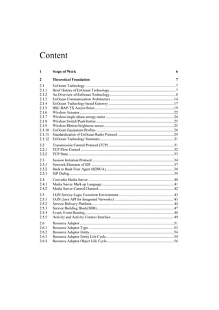
mission. A small example scenario demonstrating the EnOcean Technology is shown in
figure 2.1.1.](https://image.slidesharecdn.com/masterarbeitchandpiyush-111025052413-phpapp01/85/Master-Arbeit_Chand-_Piyush-8-320.jpg)
![2.1 EnOcean Technology 9
2.1.1 Figure showing a complete optimizing heating and cooling solution based on EnOcean Technology [Enoc3]
Figure 2.1.1, shows a complete EnOcean based heating and cooling solution. The figure
consists of a Energy control which communicates with all the devices like Room temperature
sensor, humidity sensor, CO2 sensor, Contact temperature sensor for both air conditioner and
the heater, Window contact and Window handle sensor for ventilation. This is consider as an
example home automation scenario for heating, ventilation, air-conditioning.
The Concept of EnOcean Technology is mentioned in [ENOC3] states that Energy harvest-
ing wireless switches and sensors for Green-Smart-Wireless. The idea that led to this innova-
tive technology is based on a very simple observation: where sensors capture measured val-
ues, the energy state constantly changes. When a switch is pressed, the temperature alters or
the luminance level varies. All these operations generate enough energy to transmit wireless
signals. [Enoc3]](https://image.slidesharecdn.com/masterarbeitchandpiyush-111025052413-phpapp01/85/Master-Arbeit_Chand-_Piyush-9-320.jpg)
![2.1 EnOcean Technology 10
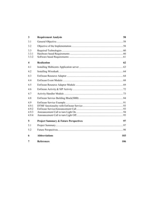
Figure 2.1.2: Energy Harvesting Wireless Sensor Solution from EnOcean Technology. [Enoc3]
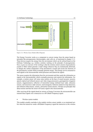
The basic principle of working of a sensor wireless module is shown in figure 2.1.2. This
framework is divided into two specific modules, the Wireless Sensor Module and the Wire-
less System Module which together combine to build up the Energy harvesting Wireless
Sensor Solution defined by EnOcean Technology.
Wireless Sensor Module :
This module consists of five basic technical building blocks which are described as follows:
1) Energy Convertor /Energy Harvesting Devices: This is the process by which
energy is derived from external sources (e.g., solar power, thermal energy,
wind energy, salinity gradients, and kinetic energy), captured, and stored for
small, wireless autonomous devices.
2) Microcontroller: This is used to utilize the embedded functionality behaviour of
the wireless sensor module. This includes the processing and controlling of the
devices depending upon the information received and also transmitted from the
module.
3) Energy Management: This sub-module adds up to the functionality of the wire-
less sensor module, it can be used to manage other sensor based devices and
Energy Converter/ Energy Harvesting Devices.
4) Sensor: This sensor is a device that will measure a physical quantity and con-
vert it into a signal which can be read by the microcontroller for processing and
controlling.
5) RF Transceiver: This sub module provides the functionality to send and receive
RF (Radio Frequency) Signals.](https://image.slidesharecdn.com/masterarbeitchandpiyush-111025052413-phpapp01/85/Master-Arbeit_Chand-_Piyush-10-320.jpg)
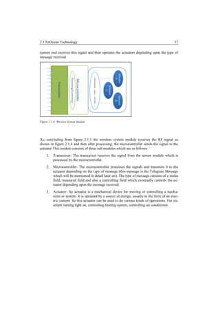
![2.1 EnOcean Technology 13
Figure 2.1.4: The complete abstract-level overview of the wireless Energy Harvesting EnOcean Technology.
The complete abstract view after combining the wireless sensor module and the wireless
system module can be seen in figure 2.1.4 which shows how Energy converters and Sensors
can be utilized to create an action on the actuator. So concluding with the same idealistic
approach some examples can be viewed. For example any motion sensor can produce an
action on the actuator to make some event like controlling the heating system.
Some of the important features of the EnOcean Technology as mentioned in [Enoc3] are as
follows:
A highly optimized automation and controlling solution.
Easy to integrate components, for example Energy converters, energy management &
radio modules, system & communication software.
Radio modules without batteries: The required operating energy is typ. 50 μWs per
radio telegram only.
Operating energy is generated by pressure, movements, light, temperature, vibration,
rotation, etc.
High transmission range: Up to 300 m outdoor up to 30 m indoor.
Minimal emission energy: Less than the spark radiation of a conventional light
switch, one million times less a mobile phone.
Reliable signal transmission, suited for systems with hundreds of sensors (since signal
transmission time is a thousand of a second only)
Reliable against external disturbances: Repeated radio signal transmission delayed at
random, using of regulated frequency ranges approved for pulsed signals only
Prearranged transmitter to receiver assignment: Four billion code numbers are fixed,
easy learning procedure (push receiver learn button and activate transmitters)
Considering all the aspects of the EnOcean Technology, the most specific feature is the En-
ergy Harvesting Concept to control home automation devices.](https://image.slidesharecdn.com/masterarbeitchandpiyush-111025052413-phpapp01/85/Master-Arbeit_Chand-_Piyush-13-320.jpg)
![2.1 EnOcean Technology 14
EnOcean Technology Technical Characteristics as mentioned in [Enoc3] are shown in figure
2.1.1, which is as follows:
Table 2.1.1: Characteristics of the EnOcean Technology modules.
Frequency 868.3 MHz or 315 MHz (depending upon on the location)
Transmission power: 6 dBm (antenna input)
Receiver sensitivity: -97 dB
Modulation type: ASK
Data rate 125 kHz
Channel bandwidth 280 kHz
Radio telegram 1 ms, variable telegram length (e.g. 53-130 bit incl. 32 Bit
sensor ID, 1-4 byte sensor data, checksum)
Transmission time 40 ms for three identical radio telegrams, delayed at
random
2.1.3 EnOcean Communication Architecture
The EnOcean Technology builds up its own communication architecture based upon actua-
tors. Based on [Enoc4] EnOcean is a patented energy harvesting wireless sensor solution
which enables to generate a signal of range from an extremely small amount of energy. From
just 50 μWs a standard EnOcean energy harvesting wireless module can easily transmit a
signal 300 meters. The secret lies in the signal duration which means that the entire process
is started, executed and completed in no more than a thousandth of a second.
Figure 2.1.5, shows the network architecture of EnOcean Technology, the bidirectional com-
ponents are gateways which communicate over TCP/IP, EIB, KNX, Modbus, these are the
standards for communication in home automation devices. The receivers are actuators which
basically communicate over RF. The battery less switches are transmitters which also com-
municate over RF. A common message protocol is followed which is known as telegram
message which allows to create any kind of activity on the actuators and sensors.](https://image.slidesharecdn.com/masterarbeitchandpiyush-111025052413-phpapp01/85/Master-Arbeit_Chand-_Piyush-14-320.jpg)
![2.1 EnOcean Technology 15
Figure 2.1.5: EnOcean Wireless Networking System with battery-less nodes. [ENOC4]
The EnOcean Technology based network communication architecture is basically divided
into two areas which are as follows:
Radio Frequency (Access Network)
TCP/IP (Transmission Control Protocol/Internet Protocol), EIB(European Installa-
tion Bus), KNX, Modbus(Wired Backbone).
The communication architecture of EnOcean Technology can be divided into two areas
which are as follows:
1) Radio Frequency based wireless communication which can be correlated to the ac-
cess network in regard to the conventional network architecture.
2) TCP/IP or any other specific backbone related protocol (e.g. LON, EIB/KNX,
Mobus) can be used to build the backbone architecture for the communication.](https://image.slidesharecdn.com/masterarbeitchandpiyush-111025052413-phpapp01/85/Master-Arbeit_Chand-_Piyush-15-320.jpg)
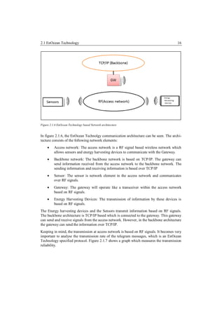
![2.1 EnOcean Technology 17
Figure 2.1.7: Transmission reliability Graph [Enoc4].
In this graph, a comparison of typical radio sensor transmission and the EnOcean technology
based transmission is compared. The number of sender transmitting data increases gradually
making. Closely analysing the graph, it can be depicted that as the number of senders in-
creases, the transmission of typical radio sensor decreases. In the same graph scale, the
transmission of EnOcean technology based sensors is much higher; this makes the possibility
of telegram collision rate to decrease. As mentioned in [Enoc4] transmission reliability is
still better than 99.99% for 100 wireless sensors each transmitting their data once a minute.
Considering this information to be accurate, it gives a possibility that a large number EnO-
cean wireless sensors and modules can be used in the same building which will transmit
reliable telegram messages.
2.1.4 EnOcean Technology based Gateway
The EnOcean Technolgy based gateway is one of the important elements in the communica-
tion architecture of EnOcean Technology. This allows to interact with the access based net-
work devices and to send the information over TCP/IP. In simple words it is a gateway
which has the capability to send and receive information over TCP/IP and also operates as a
transceiver for the energy harvesting devices and sensors, as mentioned in chapter 2.1.3.
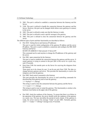
Figure 2.1.8 shows the picture of the used BSC-BAP-TX wireless access gateway. This
gateway consists of a TCM (Transceivers Module) 120 modules, this module consists of the
functionality of a wireless sensor module and a wireless system module as mentioned in
chapter 2.1.2. The TCM-120[Tcmu] module serves the 868 MHz air interface protocol of](https://image.slidesharecdn.com/masterarbeitchandpiyush-111025052413-phpapp01/85/Master-Arbeit_Chand-_Piyush-17-320.jpg)
![2.1 EnOcean Technology 18
EnOcean. It receives all signals of the EnOcean radio transmitters e.g. modules PTM (Push-
button Transceiver Module)-100 and makes them available at the serial port. The PTM is a
wireless push button controller which is a wireless switch and is mentioned in detail in chap-
ter 2.1.8.
Figure 2.1.8: A picture of the BSC-BAP-TX Gateway.[Bscb]
The gateway operates on an embedded module TCM-120. The transceiver module TCM 120
of EnOcean enables the implementation of bi-directional RF applications based on the inno-
vative EnOcean radio technology. Typical applications are bi-directional EnOcean compati-
ble radio interfaces, e.g. to existing system solutions or bus systems. The TCM 120 trans-
ceiver module serves the 868 MHz air interface protocol of EnOcean radio technology.
[Tcm1]
Important features of the BSC-BAP Access Point based on TCM 120 transceiver which are
mention in [Bscb] are as follows:
128 actuators and an optional number of transmitters that is compatible with EnO-
cean wireless technology per BAP.
It can be integrated in an existing network infrastructure.
PoE(Power over Ethernet) can be used for connection
BSC - BAP uses up to 0.5 Watts of power which makes it a very low power con-
sumption device.
EnOcean technology based devices can be integrated to the BSC-BAP. For exam-
ple, PTM-200 or PTM-100, Wireless Actuators, Wireless sensors based on EnO-
cean Technology.
There are some limitations of the gateway which are mentioned in [Bscb] and are ellabo-
rateed as follows:
1) The electrical field strength and the magnetic field strength are inversely propor-
tional to the square of the distance between the sender and the receiver. This has an
affect while transmitting RF signals.
2) Interfaces by materials like metallized foils of thermal insulator, metallized heat-
absorbing glass. These materials can reflect electromagnetic waves. A so-called ra-](https://image.slidesharecdn.com/masterarbeitchandpiyush-111025052413-phpapp01/85/Master-Arbeit_Chand-_Piyush-18-320.jpg)
![2.1 EnOcean Technology 19
dio shadow is built up behind these parts. Some figures related to the amount of
penetration of radio signals which can be created are as follows:
Table 2.1.3 EnCana RF penetration level in percentage.[Bscb]
Material Percentage of Penetration
Wood, gypsum, glass uncoated 90 to100%
Brick, pressboard 65 to 95%
Reinforced concrete 10 to 90%
Metal, aluminium pasting 0 to10%
Figure 2.1.10, shows a picture of range and penetration being decremented when an
iron acts as an obstacle between the transmissions.
2.1.9 Radio path range/-penetration, Reference:
As, it is shown on the left side of the figure 2.1.9, that the iron casts a radio shadow
between the receiver and the sensor. This is a drawback while implementing the
sensor and actuator based home automation environment. On the right side of the
figure 2.1.9, the effective range of radio frequency between two receivers. As one is
receiving a very good range of radio frequency and the other one is receiving it at a
slightly lower level.
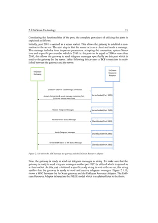
2.1.5 BSC-BAP-TX Access Point
The industrial name provided to the EnOcean Gateway is BSC-BAP-TX Access Point
[Bscb].This gateway operates on 5 ports; all these 5 ports define a specific functionality
depending upon the different types of functions which can be used. In this section, a detail
overview about the EnOcean Gateway Ports is described. The 5 ports can be utilized on the
bases of network programming, specifically client server programming. To mention in detail
among the 5 ports, 2 ports work as a client socket where the remaining 3 work as a server
socket. Following is a list of Ports which is utilized to use the functionality of the EnOcean
Gateway:
1) 2010: This port is used to configure the IP address of the EnOcean Gateway](https://image.slidesharecdn.com/masterarbeitchandpiyush-111025052413-phpapp01/85/Master-Arbeit_Chand-_Piyush-19-320.jpg)
![2.1 EnOcean Technology 22
After, completing the connection and the ready state, the gateway is ready to receive tele-
gram messages from the server. To send a telegram message to the gateway a specific port
2005 is used, which is opened as a client. On this port telegram messages are sent which
allow any kind of activity on the EnOcean device depending upon type of telegram message.
For closing the connection between the gateway and the server, another port 2002 is used.
On this port a specific string >>>>byebye<<<< is sent which closes the connection between
the gateway and the server.
Table 2.1.2 List of the EnOcean gateway ports and their functionality
Port Functionality Type of Socket
2001 Establish Connection, gateway Server Socket
can receive a special message.
2100 Special port to receive messages Server Socket
from the gateway.
2003 To make sure gateway is ready Client Socket
2005 To send telegram messages Client Socket
2002 To send message for closing Client Socket
connection or resetting connec-
tion.
2.1.6 Wireless Actuator
The wireless actuator [Elta1] is an impulse switch with integrated functionality to the EnO-
cean communication architecture. Some of the important features as mentioned in related to
the devices are mentioned below:
The universal impulse switching relay can be controlled by a conventional 230 V
AC control switch.
35 wireless pushbuttons can be assigned to the wireless actuator. The wireless
pushbuttons are configured by using the learning functionality of the wireless actua-
tor.
Wireless window/door contacts can also be configured to the wireless actuator. In
this scenario there can be two possibilities: firstly the window/door is opened this
can be facilitated to the wireless actuator by using the normally open (N/O) contact
functionality; secondly window/door is closed by using normally closed (N/C) con-
tact while the window is closed.
The wireless actuator consists of functionalities which can be configured depending
upon the requirements. Following is a table which shows some configuring features
of the wireless actuator:](https://image.slidesharecdn.com/masterarbeitchandpiyush-111025052413-phpapp01/85/Master-Arbeit_Chand-_Piyush-22-320.jpg)
![2.1 EnOcean Technology 23
Table 2.1.3 Configuration mode of the wireless actuator
Configuring modes Configuring functionality
ER Switching relay
ESV Impulse switch. Possibly with off delay
+ = ESV with push-button permanent light
+ = ESV with switch-off early warning
+ = ESV with push-button permanent light and switch-off early warning.
LRN Using this configuration field a push button can be made to learn with
the wireless actuator.
CLR This configuration filed is used to clear old set configuration mode.
The following figure 2.1.11 shows the place on the wireless actuator where the configuration
related to the above mentioned functionalities can be done.
Figure 2.1.11: Wireless Actuator[Elta1]
The wireless actuator consists of two configuration section:
One is to configure the functionality of the wireless actuator depending upon the require-
ments as mentioned in table 2.1.3; this section can be seen as the configuring mode place on
the wireless actuator. The other section is the time relay configuration section which allows
the wireless actuator to modify the time relay of the receiving signals, this makes it possible
to expand the communication architecture if many actuators are located in a home or build-
ing.](https://image.slidesharecdn.com/masterarbeitchandpiyush-111025052413-phpapp01/85/Master-Arbeit_Chand-_Piyush-23-320.jpg)
![2.1 EnOcean Technology 24
2.1.7 Wireless single-phase energy meter
The wireless single-phase [Elta2] energy meter measures active energy by means of the cur-
rent between input and output and transmits the consumption and meter reading over the RF
signal.
Figure 2.1.12: Wireless Single Phase Energy Meter [Elta2]
Some of the important features of the Wireless Single phase Energy Meter [Elta2] are as
follows:
The wireless energy meter gives a reading only when the power consumption is
more than 0.3 watt active power.
Only a one phase conductor with a maximum current up to 16A (Amperes) can be
connected.
The rush in current is 20mA.
The reading of the energy consumed is saved to a non-volatile memory and is im-
mediately available again after a power failure.
The change in power status by 10 % enables the wireless energy meter to send a
telegram message within 20 seconds.
A full telegram comprising meter reading and power status is transmitted after
every 10 minutes.
When the power supply is switched on, a teach-in telegram is sent to teach in the as-
sociated energy consumption indicator.](https://image.slidesharecdn.com/masterarbeitchandpiyush-111025052413-phpapp01/85/Master-Arbeit_Chand-_Piyush-24-320.jpg)
![2.1 EnOcean Technology 25
2.1.8 Wireless Switch/Push-button
The wireless switch/push-button as mentioned in [Elta3], operates with in the access net-
work. RF signals are used for the transmission of telegram messages. Figure 2.1.13 shows an
example of a single rocker switch which can be used to send telegram messages within the
RF signal. The wireless switch is based on the PTM -100. As, mentioned in [Ptms], this
module is based on the principle of electro-dynamic energy transducer, which sends out RF
signals when the button is pressed and released.
Figure 2.1.13: Wireless Switch/Push Button [Elta1]
Important features of the wireless push button [Elta3] are as follows:
The Wireless push-buttons with one rocker, one rocker push button means that only
one button can be used to evaluate the functionality of transmitting telegram mes-
sages over RF signals. It transmits two evaluable signals: press rocker up and press
rocker down.
Wireless push-buttons with double rocker can transmit four evaluable signals: press
two rockers up or down.
2.1.9 Wireless Motion/brightness sensor
The wireless motion sensor [Elta4] operates within the access network of the EnOcean com-
munication architecture, this enables the device to send telegram messages over RF signals
to the EnOcean gateway. Figure 2.1.14 shows a figure of the wireless motion sensor.](https://image.slidesharecdn.com/masterarbeitchandpiyush-111025052413-phpapp01/85/Master-Arbeit_Chand-_Piyush-25-320.jpg)
![2.1 EnOcean Technology 26
Figure 2.1.14: Wireless Brightness/ Motion Sensor
Important features of the wireless motion sensor [Elta4] are as follows:
The wireless motion sensor transmits telegram messages to the EnOcean wireless
access network after every 100 seconds.
The wireless motion sensor transmits two signals instantaneously after detecting
motion.
The switch-off signal is sent after the off delay which has a fixed setting of 1 min-
ute.
The motion sensor transmits signals with the information of the status every 20
minutes.
2.1.10 EnOcean Equipment Profiles
In this chapter, information with respect the EnOcean Equipments Profiles and the telegram
messages will be provided. The EnOcean Equipment profile is a specification on which tele-
gram messages can be created. The telegram message is message stack which is transmitted
on RF signals. The EnOcean Equipment Profile provides the information of the telegram
stack which is described in this chapter. Based on [Eepv1], the telegram message stack can
be created which can provide functionalities like turning light ON and turning light OFF.
Definition: The EnOcean Equipment Profile (EEP) is a unique identifier that describes the
functionality of an EnOcean device irrespective of its vendor. [Eepv1]
During the time of development a new EnOcean Equipment Profile is being released, this
profile introduces some more functionality like Smart Ack, Remote management (RPC),
MSC telegram, Bi-directional profiles (4 BS).
New Definition: The ERP specification defines the structure of the entire radio telegram.
The user data embedded in this structure is defined by the EEP. [Eepv2]](https://image.slidesharecdn.com/masterarbeitchandpiyush-111025052413-phpapp01/85/Master-Arbeit_Chand-_Piyush-26-320.jpg)
![2.1 EnOcean Technology 27
However, in this chapter the old specification [Eepv1] is being explained as during the reali-
zation phase, the old specification [Eepv1] is being used. In chapter 2.1.11, a small descrip-
tion about the new functionality and a new radio protocol stack is mentioned.
The EEP (EnOcean Equipment Profile) is defined on the bases of EnOcean technology de-
fined fields:
ORG: Identifies the EnOcean Messages which allows the communication of the
EnOcean devices.
FUNC: This field represents the basic functionality of the data content in the tele-
gram message.
TYPE: This field represents type of device in its individual characteristics.
In figure 2.1.15, the telegram stack is presented, in this figure it can be seen how the tele-
gram stack is organized and which fields are useful for developing an EnOcean message.
Figure 2.1.15: Telegram Stack [Tcmu]
The Data_Byte field represents the FUNC field of the telegram message that provides the
functionality of the telegram message. The FUNC field describes the type of activity to be
created. So the functionality to make a light to turn on or off is handled by this field. The
ID_BYTE field represents the TYPE field of the telegram message. Figure 2.1.15 elaborates
the functionality of the telegram stack in detail. The main functionality of the telegram mes-
sage stack can be understood by the figure 2.1.16. In this figure basically the complete stack
is explained.](https://image.slidesharecdn.com/masterarbeitchandpiyush-111025052413-phpapp01/85/Master-Arbeit_Chand-_Piyush-27-320.jpg)
![2.1 EnOcean Technology 28
Figure 2.1.16: Detail Description of the EnOcean Telegram [Tcmu]
Following a detailed description of the Telegram message is provided:
1. SYNC_BYTE: This field of the stack is used for synchronization of received bytes
and sent bytes. It consists of two sync bytes which are 8 bits each. [Tcmu]
2. H_SEQ: This field of the stack is the Header Sequence; this field identifies which
type of function the telegram message will implement. The length of this field is of
3 bits. [Tcmu]
Types of telegram functions:
3. RRT (Received Radio telegram): the function to receive radio data telegram on the
BSC-BAP-TX [Bscb] gateway.
4. TRT (Transmit Radio Telegram): This function of the telegram message provides
the function to transmit radio data telegram to the BSC-BAP-TX [Bscb] gateway.
5. RMT (Receive Message telegram): This function of the telegram message provides
the function to receive telegram messages from the energy harvesting devices.
6. TCT (Transmit Command Telegram): This function of the telegram message pro-
vides the function to send command telegram messages which means, the energy
devices can be controlled by using this telegram message.
7. LENGTH: This field of the stack provides the information about the number octets
following the header octet. This field length is of 5 bits and combines with H_SEQ
field to complete 1 Byte of the telegram stack.
8. ORG: This field defines which type of telegram is used within the telegram stack.
For TCM-120 module there are 6 types of telegram messages, which are shown in](https://image.slidesharecdn.com/masterarbeitchandpiyush-111025052413-phpapp01/85/Master-Arbeit_Chand-_Piyush-28-320.jpg)
![2.1 EnOcean Technology 29
figure 2.1.16, in this figure the ORG can be distinguished on the bases of the type of
functionality. [Tcmu]
Figure 2.1.17: Detail Description of the ORG Field[Tcmu]
A new version of the EnOcean Equipement profile is also available, in this specification new
functionalities have been added to make it KNX association standard. The new specification
mentioned on [eepv2] has the following changes which are as follows:
New 4 BS telegrams
Smart Ack [Enoc6 ]
Remote management (RPC) [Enoc7]
MSC telegram [Eppv2]
Bi-directional profiles (4 BS) [Eppv2]
Introduction of Encryption in the presentation layer[ Enoc8]
2.1.11 Standardization of EnOcean Radio Protocol
In this sub chapter a detail description about the standardization of the EnOcean Radio Pro-
tocal is provided. In this chapter the new standard as mentioned in [Enoc8] is explained. As
mentioned in chapter 2.1.10, a new specification is released. The new specification follows
this standard.
A standardized set of radio protocol is utilized by the EnOcean technology based devices.
This determines the transmission layer of the EnOcean technology based devices. Figure](https://image.slidesharecdn.com/masterarbeitchandpiyush-111025052413-phpapp01/85/Master-Arbeit_Chand-_Piyush-29-320.jpg)
![2.1 EnOcean Technology 30
2.1.18, shows a table of the standardized EnOcean Radio Protocol. The transmission layer is
divided into 7 layers which are as follows:
1) Application Layer: At this layer of the EnOcean Standard the Data interpretation
with respect to the EnOcean Equipment Profile is utilized.
2) Presentation Layer: This layer of the EnOcean Standard, introduces to some basic
functionalities like data encryption, data decryption, encapsulating and decapsulat-
ing the retrieve and transmitted data.
3) Session Layer: No functionality of creating a session is utilized in the EnOcean Ra-
dio Protocol till yet maybe it can be enhanced for future.
Figure 2.1.18 Standardization of EnOcean Radio Protocol [Enoc8]
4) Physical Layer: the Physical layer operates at the RF Signal level which considers
functionalities related to bit sampling, carrier frequency, modulation, data rate, Tx
power, Rx sensitivity
5) Transport Layer: This layer provides the functionality of remote management,
Smart Ack. Smart Ack enables bidirectional communication. The communication
is managed by a Controller that responds to the devices telegrams with acknowl-
edges, for more information please refer to document. [Enoc8], [Enoc6]](https://image.slidesharecdn.com/masterarbeitchandpiyush-111025052413-phpapp01/85/Master-Arbeit_Chand-_Piyush-30-320.jpg)
![2.2 Transmission Control Protocol (TCP) 31
6) Network Layer: This layer provides functionality of addressing, networking, rout-
ing, switching, and repeating. The routing and repeating of the telegram messages is
operated on the bases of the decoded telegram messages. Important decoded tele-
gram message fields at the bytes level are utilized.
7) Data Link Layer: This layer provides functionality of decoding and encoding the
telegram messages like synchronization of bits, checksum of bits, CRC (cyclic re-
dundancy check) for error detection and LBT (Listen Before Back). LBT is a tech-
nique used in wireless communications whereby a wireless transmitter or repeater
first senses its wireless environment before starting a transmission. The aim is to
avoid collisions with other senders. It is an optional feature of the transmitting de-
vice. [Enoc8]
2.1.12 EnOcean Technology Summary
The EnOcean Technology is known as a standard for home automation devices which makes
it possible for various kinds of actuators and sensors located in the home to communicate
with each other. The main advantage is that the transmitting devices which are based on
energy harvesting technique that means these devices acquire the energy from the environ-
ment based on simple concepts of electrical and mechanical engineering. The provision of
the gateway makes it possible to extend the EnOcean Technology based communication
architecture. The above mentioned devices are the important elements of EnOcean Teach-
nology. There are many other kinds of home devices performing heating and cooling tech-
niques based on sensors and actuators on the same principle.
2.2 Transmission Control Protocol (TCP)
The TCP [793] is one of the core protocols of the Internet Protocol Suite. This protocol is
specified in RFC -793, which provides all the information about TCP. The concept was first
mentioned by Cerf and Kahn. This protocol came to existence from September 1981 and
was developed by IETF (Internet Engineering Task Force).As, mentioned in [793] TCP is a
connection-oriented, end-to-end reliable protocol designed to fit into a layered hierarchy of
protocols which support multi-network applications. The TCP provides reliable inter-process
communication between pairs of processes in host computers attached to distinct but inter-
connected computer communication networks. It is intended to provide a reliable process-
to-process communication service in a multi network environment. The main functionality is
connection establishment based on three way handshake concept, sequencing number, flow
control, after timeouts repetition of a TCP message by transmitter, multiplexing of TCP
connection by ports and sockets, checksum with header and data.](https://image.slidesharecdn.com/masterarbeitchandpiyush-111025052413-phpapp01/85/Master-Arbeit_Chand-_Piyush-31-320.jpg)
![2.2 Transmission Control Protocol (TCP) 32
2.2.1 TCP Flow Control
TCP is based on the logical concept of flow control; the flow control is basically based on
the different types of control flags which provide the information of the three way hand
shake between a server and a client.
As, mentioned in [793], TCP provides a means for the receiver to govern the amount of data
sent by the sender. This is achieved by returning a "window" with every ACK indicating a
range of acceptable sequence numbers beyond the last segment successfully received. The
window indicates an allowed number of octets that the sender may transmit before receiving
further permission.
The connection is initiated by a client and then the server sends back an acknowledgement to
the user to establish a connection. After the connection that client sends the datagram packets
to the server. This operation is flowed back and forth between the client user and the server,
until the required data is transmitted. In the end to release the TCP connection another pa-
rameter is set. There is defined TCP terminology based on the functionality of TCP which is
known as control flags. The communication in TCP is based on control flags which are as
follows:
1. SYN = 1: This value provides the information that the TCP-connection establish-
ment is initiated.
2. ACK = 1: This value provides the information of the Acknowledgement of a re-
ceived TCP-packet.
3. FIN = 1: This value provides the information that a TCP-connection is release.
The above mentioned control flags are the basic principle of communication in TCP, Figure
2.2.1 shows an example of the control flags between a client and a server.](https://image.slidesharecdn.com/masterarbeitchandpiyush-111025052413-phpapp01/85/Master-Arbeit_Chand-_Piyush-32-320.jpg)
![2.2 Transmission Control Protocol (TCP) 33
1. The client sends a SYN packet
to establish a connection.
2. The server sends an ACK
packet to acknowledge the
SYN packet.
3. The client completes the three-
way handshake.
4. The client sends the actual re-
quest.
5. The client sends a FIN packet
to indicate that it is done send-
ing.
6. The server acknowledges the
request and the FIN.
7. The server sends the reply
back to the client.
8. The server sends a FIN packet
to indicate that it is also done.
9. The client acknowledges the
server's FIN.
Figure 2.2.1 Example of TCP Control Flow[Tsac ]
2.2.2 TCP State
Based on the logic of the flow control in the TCP, complete state can be seen in table 2.2.1.
The handling of the gateway and the application server is based on TCP. The connection is
established on a specific port and other functionalities are handled on various other ports
which are described in chapter 2.2.1, while developing the network interface between the
application server and the EnOcean gateway based on [Jain], it becomes essential to analyse
the TCP connection between the EnOcean gateway and the Application Server. Based on
[793] Following is a list of state:
Table 2.2.1 TCP state table
State Functionality
LISTEN Represents waiting for a connection request from any remote TCP and port.
Represents waiting for a matching connection request after having sent a connection
SYN-SENT request.
Represents waiting for a matching connection request
SYN-RECEIVED
Represents an open connection, data received can be delivered to the user. The normal
ESTABLISHED state for the data transfer phase of the connection.](https://image.slidesharecdn.com/masterarbeitchandpiyush-111025052413-phpapp01/85/Master-Arbeit_Chand-_Piyush-33-320.jpg)
![2.3 Session Initiation Protocol 34
Represents waiting for a connection termination request from the remote TCP, or an
acknowledgment of the connection termination request previously sent.
FIN-WAIT-1
Represents waiting for a connection termination request from the remote TCP.
FIN-WAIT-2
Represents waiting for a connection termination request from the local user.
CLOSE-WAIT
Represents waiting for a connection termination request acknowledgment from the
CLOSING remote TCP.
Represents waiting for an acknowledgment of the connection termination request previ-
ously sent to the remote TCP (which includes an acknowledgment of its connection
LAST-ACK termination request).
The above table gives the information of all the possible states, while the TCP communica-
tion is established between a client and a server. During the implementation the TCP com-
munication is one of the important protocols to analyse as the EnOcean gateway communica-
tion with the Application Server is based on TCP/IP.
2.3 Session Initiation Protocol
The Session Initiation Protocol (SIP) is a signalling protocol used for establishing sessions in
an IP network. The first RFC of SIP was 2543 which was published in 1992. After that many
RFC have been created. The most recent RFC is 3261. To design a simpler and more modu-
lar way to do voice over IP, SIP was standardized in 1999 by the Internet Engineering Task
Force (IETF). SIP makes it possible to use it for signalling between two user agents. Based
on SIP, two-party sessions that are ordinary telephone calls, multiparty sessions that allow
everyone to hear and speak, and multicast sessions which means one sender, many receivers
can be realized. The session may contain audio, video, or data, the latter being useful for
multiplayer real-time games. SIP just handles setup, management, and termination of ses-
sions. Other protocols, such as RTP (Real Time Protocol) and RTCP (Real Time Communi-
cation Protocol), are used for data transport. SIP is an application-layer protocol and can run
over UDP [768] or TCP. SIP is a request-response protocol that closely resembles two other
Internet protocols, Hyper Text Transfer Protocol (HTTP) and Simple Mail Transfer Protocol
(SMTP). SIP is compatible with Internet applications.
According to RFC 3261, SIP is an application-layer control protocol that can establish, mod-
ify, and terminate multimedia sessions (conferences) such as Internet telephony calls. SIP
can also invite participants to already existing sessions, such as multicast conferences. Me-
dia can be added to (and removed from) an existing session. SIP transparently supports
name mapping and redirection services, which supports personal mobility.](https://image.slidesharecdn.com/masterarbeitchandpiyush-111025052413-phpapp01/85/Master-Arbeit_Chand-_Piyush-34-320.jpg)
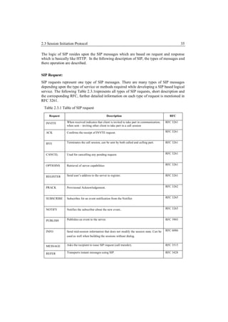
![2.3 Session Initiation Protocol 36
UPDATE Modifies the state of the session without changing the dialog. RFC 3311
In the above table mostly the first five requests INVITE, ACK, BYE, CANCEL, OPTIONS,
REGISTER based on [3261] are used between a UAC and a UAS. The INFO message pro-
vides add on functionality for the UAC, while communicating with the AS.
SIP response:
SIP responses are the second type of SIP messages, they complement the SIP requests. The
first line in a SIP response is called “status line” or “status code”. The responses are divided
according to the type of the status code as follows:
Informational
Success
Redirection
Request failure
Server-error
Global failure
Table 2.3.2 Table of SIP Response
Response Type Functionality RFC
1xx: Provisional request received, continuing to process the request; RFC 3261
2xx: Success action was successfully received, understood, and accepted; RFC 3261
3xx: Redirection further action needs to be taken in order to complete the request; RFC 3261
4xx: Client Error request contains bad syntax or cannot be fulfilled at this server; RFC 3261
5xx: Server Error server failed to fulfill an apparently valid request; RFC 3261
6xx: Global Failure Request cannot be fulfilled at any server. RFC 3261
Table 2.3.2, shows all the necessary response messages which are handled by a proxy server,
application server or a media server. The response can further be extended, depending upon
their properties. The “1xx”, only shows the series of provisional response type messages
send out. However, there is a list of messages in the same series which can be referred from
the specific RFC.](https://image.slidesharecdn.com/masterarbeitchandpiyush-111025052413-phpapp01/85/Master-Arbeit_Chand-_Piyush-36-320.jpg)
![2.3 Session Initiation Protocol 37
2.3.1 Network Elements of SIP
There are many network elements based on SIP but they can broadly be divided into SIP user
agent and the SIP server. The user agent can be of two types: SIP user agent client (UAC)
and the SIP user agent server (UAS).
SIP User Agent client: This element initiates request to start a session between the user
agent and the application server.
SIP User Agent server: This element generates responses to the request made by the UAC.
There are several network elements defined in the RFC 3261. Some of the important network
elements are as follows:
1. A proxy server, as mentioned in [3261] "is an intermediary entity that acts as both a
server and a client for the purpose of making requests on behalf of other clients. A
proxy server primarily plays the role of routing, which means its job is to ensure
that a request is sent to another entity "closer" to the targeted user. Proxies are also
useful for enforcing policy (for example, making sure a user is allowed to make a
call). A proxy interprets, and, if necessary, rewrites specific parts of a request mes-
sage before forwarding it." The proxy server is responsible for routing and sending
out the request to the specific UAC.
2. A registrar, as mentioned in [3261], “is a server that accepts REGISTER requests
and places the information it receives in those requests into the location service for
the domain it handles." The UAC can register to this server which identifies the
user’s location.
3. A redirect server, as mentioned in [3261] “is a user agent server that generates 3xx
responses to re-quests it receives, directing the client to contact an alternate set of
URIs. The redirect server allows SIP Proxy Servers to direct SIP session invitations
to external domains.” The redirect server is responsible for redirecting any SIP re-
quests. The redirection of the request depends upon the “to” header field.](https://image.slidesharecdn.com/masterarbeitchandpiyush-111025052413-phpapp01/85/Master-Arbeit_Chand-_Piyush-37-320.jpg)
![2.3 Session Initiation Protocol 38
Figure 2.3.1 A simple peer to peer SIP call between two UAC [Tsac]
There can be many scenarios to explain the concept of a SIP call, in figure 2.3.1 a simple SIP
call is shown in which there are four SIP based network elements, the caller, the callee, the
Proxy server, and the Location server. Considering that the caller and the callee are regis-
tered to a register server. The procedure of the call can be seen by the sequences of the
number indicated in the figure 2.3.1. So basically, the caller makes a call sends an INVITE to
the Proxy server, the Proxy server looks up in the Location server and checks if the called
SIP URI is located on the server meaning there by the mapping between the permanent SIP
URI and the temporary URI is created on the basis on the register server which by the way is
not mentioned in figure 2.3.1. After looking up the SIP URI, the location server sends a reply
to the proxy server. The proxy server sends an INVITE to the callee, assuming that the callee
accepts the call; an OK is send to the Proxy Server. The proxy server sends an OK to the
caller; the caller receives the OK and sends an ACK to the Proxy server. To start the session
between the caller and the callee, the proxy server sends the final ACK. In the end a peer to
peer connection is established between the caller and the callee for a SIP based call. The
server functionality can reside on a single machine which can handle all the back end service
including location, redirection, registration and also proxy server functionality.
2.3.2 Back to Back User Agent (B2BUA)
A B2BUA is a SIP logic that receives a SIP request, reformulates it, and then sends it out as
a new request. Responses to the new request are also reformulated and send back out in the
opposite direction. In the realized service example, the application server acts as a back to](https://image.slidesharecdn.com/masterarbeitchandpiyush-111025052413-phpapp01/85/Master-Arbeit_Chand-_Piyush-38-320.jpg)
![2.3 Session Initiation Protocol 39
back user agent which means the application sends out responses and also requests depend-
ing upon the behaviour of the service. In the scenario the application server controls the SIP
messages between the user agent and the media server, this behaviour of the application
server is like a back to back user agent. Figure 2.3.2 shows a B2BUA, which theoretically
demonstrates the logic.
Figure 2.3.2 Example of a Back to Back User Agent [Sipc]
In this example service for both the user agents 1 and 2, the SIP server operates as a B2BUA,
which shows that it contains the functionality of UAC and the UAS. When a request is re-
ceived by the B2BUA, the B2BUA reformulates the header bodies and then forwards the
request to the other user agent. Similarly, when response is received by the B2BUA, the
server can reformulate the header fields and send it to the necessary UAC.
According to RFC-3261, a back-to-back user agent (B2BUA) is a logical entity that receives
a request and processes it as a user agent server (UAS). In order to determine how the re-
quest should be answered, it acts as a user agent client (UAC) and generates requests.
Unlike a proxy server, it maintains dialog state and must participate in all requests sent on
the dialogs it has established. Since it is a concatenation of a UAC and UAS, no explicit
definitions are needed for its behaviour.
2.3.3 SIP Dialog
The SIP dialog is an important concept while implementing the service as mentioned in
chapter 4. The dialog is basically between two user agents, or between two servers or be-
tween user agent and server.](https://image.slidesharecdn.com/masterarbeitchandpiyush-111025052413-phpapp01/85/Master-Arbeit_Chand-_Piyush-39-320.jpg)
![2.4 Convedia Media Server 40
As mentioned in [3261], a “Dialog is a peer-to-peer relationship between two user agents. It
represents a context that facilitates the sequencing of messages between the user agents and
proper routing of requests between them. The dialog represents a context in which to inter-
pret SIP messages.”
In context of SIP, a dialog is created between two user agents. After establishing a session, a
dialog becomes an important concept in SIP which allows the possibility of interpreting
various SIP messages during the dialog. Each dialog is identified at each UA by three pa-
rameters: Call-ID value, a local tag and a remote tag, bringing all these tags together a dialog
ID is created which is responsible to identify a specific dialog between two user agents. Dur-
ing the realization of the service the following dialogs are created between the following
elements:
UAC (User Agent Client) and AS (Application Server).
AS and MS (Media Server).
UAC and MS.
2.4 Convedia Media Server
The RadiSys Convedia CMS-3000 media server delivers carrier-class media processing
capabilities for enterprise IP telecommunication services. Increased processing power, in-
cluding I/O throughput upgrades, delivers significant performance improvement for Voice
XML (Extensible Markup Language) based on IVR and messaging applications, while deliv-
ering multi-service versatility for numerous applications including IP PBX, instant video
conferencing, IP contact centres, and unified communication solutions. [Conv]
The Convedia media server is a hardware based server which provides variety of media re-
lated services like call conferencing, announcement calls etc. It is valuable server for IP
based telecommunication infrastructure which supports in providing media based value
added services. The main functionality of the media server lies with the MSML (Media
server mark up language) [5707], more information about the MSML is mentioned in chapter
2.4.1. Basically MSML is a type of XML which supports media functionalities. The func-
tionality of the media server can be utilized by using the MSML which stores the required
data types as XML, which eventually can be accumulated for various kinds of media based
services. The media server supports many media functionalities which include DTMF( Dual
Tone Multi-Frequency), recording and playback, stream connection which provides intercep-
tion support for video and audio, video announcements, IVVR(Interactive Voice and Video
Response). In the implementation of the EnOcean service DTMF functionality is used which
actually demonstrates the behaviour in respect to the controlling of EnOcean devices.](https://image.slidesharecdn.com/masterarbeitchandpiyush-111025052413-phpapp01/85/Master-Arbeit_Chand-_Piyush-40-320.jpg)
![2.4 Convedia Media Server 41
2.4.1 Media Server Mark up Language
Based on the RFC 5707, The Media Sessions Mark-up Language (MSML) is an XML (Ex-
tension Mark-up Language) language used to specify and change the flow of media streams
within a media server. MSML is designed for manipulating media services offered by the
media server to established media sessions based on SIP [3665]. As mentioned in [5707],
MSML specifies how media sessions on the media server interact, and controls and invokes
media services on the media server. For example, MSML can be used to create conferences
and join sessions into conferences. The MSML is handled by SIP which operates as a signal-
ing protocol and creates a session between the media server and a controlling agent. The
session acts as a control channel which is described in sub-chapter 2.4.1. During this session,
the user agent can utilize the functionality of the media server which are mentioned in chap-
ter 2.4.
MSML can also be used with MOML (Media Objects Markup Language) to interact with
individual users or with groups of conference participants, for example applying IVR opera-
tions, called “dialogs,” to sessions or conferences. Using MSML, it is also possible to control
advanced conferencing features on a media server, to modify media while a session is in
progress, and to perform advanced session manipulation such as personalized mixing.
MSML transactions are originated by application domain events. These events can be inde-
pendent of any media or user interaction. For example, an application may play an an-
nouncement to a conference warning that its scheduled completion time is approaching.
MSML is designed to be used with other languages. For example, MSML does not set up or
teardown sessions. Instead, MSML uses a transport protocol such as SIP for that purpose.
[5707].
The Media Objects Mark up Language based on [5707] generates a media object which is an
endpoint of one or more media streams. It may be a connection that terminates RTP sessions
from the network or a resource that transforms or manipulates media. MSML defines four
classes of media objects. Each class defines the basic properties of how object instances are
used within a media server. However, most classes require that the function of specific in-
stances be defined by the client, using MSML or other languages such as VoiceXML.](https://image.slidesharecdn.com/masterarbeitchandpiyush-111025052413-phpapp01/85/Master-Arbeit_Chand-_Piyush-41-320.jpg)
![2.4 Convedia Media Server 42
Figure 2.4.1 Example of a MSML
Figure 2.4.1, shows an example of a MSML which is used to utilize the functionalities based
on the Convedia Media Server. The MSML is created on the basis of [Msml]. In this exam-
ple the dialogstart target, play id, send target, record destination, send target are the parent
elements which consists of substitute child elements to enable the service media functionali-
ty.
MSML does not directly constrain the media processing language. However, the current
implementation of MSML on the Convedia Media Server supports only MOML as a media
processing language. While MSML addresses the relationships of media streams (in, for
example, simple and advanced conferencing), MOML is an XML language that addresses
the control and manipulations of media processing operations, such as announcement, IVR,
play and record, AST/TTS, fax, and video. Together, MSML and MOML form general-
purpose media server control protocol architecture.
2.4.2 Media Server Control Channel
The media server control channel creates a session between the application server and the
Convedia Media Server. To access the functionality located on the media server based on
MSML, a control channel is to be established which allows the user agent to establish a con-](https://image.slidesharecdn.com/masterarbeitchandpiyush-111025052413-phpapp01/85/Master-Arbeit_Chand-_Piyush-42-320.jpg)
![2.5 JAIN Service Logic Execution Environment 43
nection through the application server. Figure 2.4.2, shows an example of a control channel.
The control agent can be an application server, which utilizes the functionality of the Media
Server.
2.4.2 Convedia Media Server Control Channel [Msml].
The Control channel is a SIP based three way hand shake which creates the session between
the control agent and the Media Server. When the control channel is created, SIP based IN-
FO messages can be send to the media server which provides the UA to use media functio-
nality presiding on the media server. Creating the control channel is a fundamental logic to
utilize the functionality of the Convedia Media server. This logic is used during the realiza-
tion of the EnOcean Service.
2.5 JAIN Service Logic Execution Environment
In this chapter the Java API for Integrating Networks Service Logic Execution Environment
is described. Basically, JSLEE is a fundamental architecture for a service delivery platform
which has an extremely deep conceptual model. In this chapter the important concepts and
logics with respect to JSLEE is discussed.
2.5.1 JAIN (Java API for Integrated Networks)
JAIN stands for Java API for Integrated Networks. Based on [Jain3] it is an initiative, and
represents the community extension to of SJN (Sun Java Networks). It is a JAVA API for
providing next generation telecommunication services. The Development proceeds under the
terms of Sun's Java Specification Participation Agreement (JSPA). It is endorse as Sun de-
veloper Network with an initiative to unify complex wire line, wireless and IP communica-
tions interfaces into a set of industry defined Java standards. [Jain2]](https://image.slidesharecdn.com/masterarbeitchandpiyush-111025052413-phpapp01/85/Master-Arbeit_Chand-_Piyush-43-320.jpg)
![2.5 JAIN Service Logic Execution Environment 44
JAIN is supposed to integrate all existing types of networks, like IP networks, cellular, wire-
less and PSTN networks. This should be done by means of creating industry standards for
execution environments and interfaces for creating intelligent network services and applica-
tions. JAIN has a component-based architecture, which it has inherited from Java Beans
technology, meaning a robust and flexible environment with module architecture. [Jain2]
Java APIs for Integrated Networks (JAIN) is a collection of APIs that are based on Java
technology and provide access to telephone and data networks. The company Sun Microsys-
tems has introduced this extension of the Java platform in 1998 to develop network services
faster and easier. [Jain3]
2.5.2 Service Delivery Platform
JSLEE (Jain Service Logic Execution Environment), where Jain stands for Java API for
Integrated Network. As mentioned in [Sunj] JSLEE is a component model like EJB, Servlet
or JSP, and is most similar to EJB. The concept is J2EE technologies but is a specialized
component model for event driven applications. The SLEE can be implemented independent
of J2EE and used stand-alone without requiring a J2EE. The component model is designed
and developed to provide telecommunication service developers to develop much more ro-
bust.
It is a service delivery platform which provides telecommunication application service de-
velopers to implement the service in an event oriented way. The complete architecture de-
fines a component model for structuring the application logic of communications applica-
tions as a collection of reusable object-oriented components, and for composing these com-
ponents into more sophisticated services. Based on [Jain], the SLEE architecture also defines
the contract between these components and the container that will host these components at
runtime. The SLEE specification supports the development of highly available and scalable
distributed SLEE specification compliant application servers, but does not mandate any par-
ticular implementation strategy.
One of the most attractive features of the JSLEE architecture is that the applications may be
written once, and then deployed on any application server that complies with the SLEE
specification. In addition to the application component model, the SLEE specification also
defines the management interfaces used to administer the application server and the applica-
tion components executing within the application server. The JSLEE architecture provides a
highly adaptive and objects oriented based platform which makes it possible for developers
to implement service just like any other server based application but keeping in mind the
telecommunication requirements.](https://image.slidesharecdn.com/masterarbeitchandpiyush-111025052413-phpapp01/85/Master-Arbeit_Chand-_Piyush-44-320.jpg)
![2.5 JAIN Service Logic Execution Environment 45
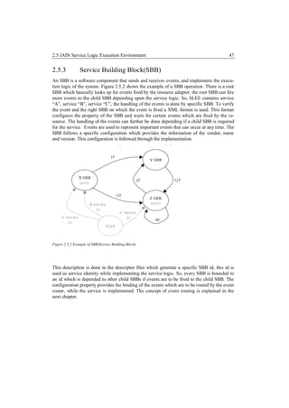
Figure 2.5.1: JSLEE Architecture [Mmjt]
SLEE is a container developed for asynchronous event driven applications. In Figure 2.5.1
the basic architecture of the JSLEE architecture can be seen which shows how exactly the
architecture is embedded. Based on [Mmjt] JSLEE can be divided into three parts which are
mentioned below:
Management: This specific component of the JSLEE architecture provides the developer to
use various management entities which includes JMX (Java Management Extension), it is a
management entity that runs in a Java Virtual Machine (JVM) and acts as the liaison between
the MBeans and the management application.
Framework: The Framework component consists of the major functionality related to event
routing, profile specification, alarming facilities and the trace. These functionalities are
JSLEE specific.
Component Model: This component consists the main building block like the SBB (Service
Building Block), the events are fired by the resource adaptor which are accumulated by the
SBB. The lifecycle of the SBB is also a part of this model. So, whenever an event based
object is generated it follows the lifecycle of the SBB. The formulation of the deployment
units are also done in this component model. The deployment is done on the bases of a spe-
cific format which the JSLEE component model can understand. The Look up for any spe-
cific facilities is also carried out in the component model. Figure 2.3.1, shows the component
model, at step 1, the RA stack consists the communicating protocol which enables the JSLE
to communicate with the external environment. At step 2, the mapping of java objects is
done on the basis of [Jain]. At step 3 the event routing is done which utilizes the developed
java objects. At step 3, the Event router routes out the required events to the tended SBB . At](https://image.slidesharecdn.com/masterarbeitchandpiyush-111025052413-phpapp01/85/Master-Arbeit_Chand-_Piyush-45-320.jpg)
![2.5 JAIN Service Logic Execution Environment 46
step 4, more child SBBs can be integrated to the main SBB. At step 5, the SBB can commu-
nicate with RA (Resource Adaptor) Stack and at step 6, the RA Stack sends out an action to
the external environment.
Figure 2.5.1: Component model of JSLEE[Mmjt]
Resource Adaptor & Resource API: This section of the JSLEE architecture allows the
JSLEE to communicate with the external environment. The example of utilizing the resource
adaptor can be seen in figure 2.3.1, where the resource adaptor, RA stack consists of a spe-
cific protocol stack to communicate to the external environment. The resource adaptor has
the property to accumulate all the functionality related to a specific communicating protocol
which allows the JSLEE to communicate with the external environment, a detail description
about the basic conventional resource adaptor is described in chapter 2.6.1.
As mention in [Jain], JSLEE is a platform containing multiple containers developed for
building applications for centric networks. SLEE is standardized to meet the needs of devel-
opers that build real-time event processing applications.](https://image.slidesharecdn.com/masterarbeitchandpiyush-111025052413-phpapp01/85/Master-Arbeit_Chand-_Piyush-46-320.jpg)
![2.5 JAIN Service Logic Execution Environment 48
2.5.4 Event, Event Routing
Events fired by the resource adaptor and the handling of the fired events are logical funda-
mental concept in the JLSEE architecture. The handling of the fired event is done by the
concept of event routing. Event can be a kind of logic behavior fired by the resource adaptor
depending upon the external resource which is based on a communication protocol. The
Event router actually routes the event to the SBB which is subscribed to the specific event.
As mention in [Uocl], an event represents an event which triggers a process, or may be part
of a process. Also includes event information describing the event, such as the source of the
event. In addition, an event can be generated from various sources, such as external resources
that are tied to the resource adapter using JSLEE, JSLEE by itself or by the application com-
ponents within the JSLEE.
Figure 2.5.3: The concept of event and event routing [Mobi3].
In figure 2.5.3, the Resource Adaptor fires an event which is handled by the event router.
The event router forwards the event to the required SBB. The Events are represented within a
JSLEE through event objects that are used to distribute information to the resource adapter or
SBBs to exchange information among root SBBs and child SBBs. The transfer of an event
takes place on an Activity Context. Each event object corresponds to a defined event type.
The event router ensures that the events of a given type are forwarded to the SBBs who are
interested in receiving events of such type.
The event routing between resources and the JSLEE components and the routing of events
between components, is one of the basic functions of JSLEE. In the JSLEE the event model
is based on publish-subscribe model. Based on [Jain] this model decouples the component](https://image.slidesharecdn.com/masterarbeitchandpiyush-111025052413-phpapp01/85/Master-Arbeit_Chand-_Piyush-48-320.jpg)
![2.5 JAIN Service Logic Execution Environment 49
that generated the event of the consumers of that event by the event-routing mechanism, the
distribution of events, from event to event producer-consumer, takes over. So, basically, the
resource adaptor works as a publisher which publishes out events and the event router sub-
scribes to the published event.
2.5.5 Activity and Activity Context Interface
The activity and the activity context interface is an important concept in the JSLEE architec-
ture. This makes it possible for the SBB to interact with different kinds activities which are
formulated in the JSLEE. As mentioned in [Jain], “An Activity represents a related stream of
events. These events represent occurrences of significance that have occurred on the entity
represented by the Activity. From a resource’s perspective, an Activity represents an entity
within the resource that emits events on state changes within the entity or resource.”
The activity is entitled to events which fires out events in the JSLEE and the SBB entity can
capture those events and use that event for the Service Logic. Figure 2.5.5, shows an exam-
ple of the activity which fires out events to the SBB entity which can then utilize the activity
in the service building logic. The activity is handled by a resource that can be a resource
adaptor which formulates the concept behind the activity depending upon the resource adap-
tors functionality.
Figure 2.5.4: Example for the Activity in JSLEE [Sunj]
The activity context interface is another important concept in the JSLEE architecture. It is an
interface between the SBB entity and the Activity which is handled by the resource domain.
Basically the Activity fires out events to the SLEE Domain which can be handled by the
SBB over the activity context interface.](https://image.slidesharecdn.com/masterarbeitchandpiyush-111025052413-phpapp01/85/Master-Arbeit_Chand-_Piyush-49-320.jpg)
![2.5 JAIN Service Logic Execution Environment 50
Figure 2.5.5: Example of the Activity Context Interface and the Activity [Sunj]
The Activity Context interface can be utilized by many SBBs, various useful objects can be
stored in the Activity Context interface to maintain a persistence service. Even, the Activity
can be stored in the Activity Context Interface which allows the SBB to utilize the stored
activity in the activity context interface and then use the activity in the service logic.
The activity is a resource oriented logic which is implemented in a resource adaptor and the
resource adaptor fires outs event on an activity. On the other hand the SBB can accumulate
the event which is fired by the resource adaptor over the activity context interface. The con-
ceptual logic of the Activity and the Activity Context interface allows binding the SBB to a
resource adaptor.](https://image.slidesharecdn.com/masterarbeitchandpiyush-111025052413-phpapp01/85/Master-Arbeit_Chand-_Piyush-50-320.jpg)
![2.6 Resource Adaptor 51
2.6 Resource Adaptor
The Resource Adaptor is basically an element presented in the JSLEE architecture, which
provides the functionality to the JSLEE architecture to communicate with the external envi-
ronment. The resource adaptor is general a communication protocol driven logic which pro-
vides the functionality to the SBB (Service Building Block) to communicate on a specific
protocol. So, for example if a Service is based on the SIP protocol, a SIP resource adaptor is
used which provides the SBB to communicate to the external environment utilizing the SIP
protocol which is embedded in the resource adaptor.
In the implementation the EnOcean Resource Adaptor which is explained in chapter no. 4.3
is basically based on the TCP which allows the JSLEE based application server to communi-
cate with the EnOcean gateway. As described in [Jain], a Resource Adaptor is an implemen-
tation of one or more resource adaptor types. There may be multiple Resource Adaptors
available for a particular resource adaptor type, each providing the same contract to SBB
developers.
Figure 2.6.1 An Example of a service building block where a SBB uses many resource adaptors
Typically, a Resource Adaptor is provided either by a resource vendor or a SLEE vendor to
adapt a particular resource implementation to a SLEE. So this makes it possible for many
resource adaptors to communicate on various protocols like, SIP, TCP, and HTTP etc. The
concept and logic of the communication protocol is developed in the resource adaptor which
is accessible by the SBB.
To expand the service implementation, one SBB can be bind with many resources adaptors.
So if one service i.e. a SBB would like to use many protocols to implement the service that is
possible. A simple block diagram shown in figure no. 2.6.1 represents the conceptual logic of
using one SBB with many resource adaptors. The green oval shaped body represents the
Service building block and the blue coloured box represents the resource adaptors. This func-](https://image.slidesharecdn.com/masterarbeitchandpiyush-111025052413-phpapp01/85/Master-Arbeit_Chand-_Piyush-51-320.jpg)
![2.6 Resource Adaptor 52
tionality provides the SBB to communicate over multiple protocols and enhance more ser-
vices.
As mentioned in [Jain], a vendor may provide a Resource Adapter that adapts the SIP stack
to the SLEE. An Administrator installs Resource Adapters in the SLEE which allows an SBB
(Service Building Block) to use the functionality of the resource adaptor. Another example is
a HTTP client resource adapter, which consists of all the functionality related to a Hyper-
Text-Transfer Protocol which is based on the request and response methods. These methods
are than added to the HTTP client resource adapter which can be utilized by a SBB (Service
Building Block). The resource adaptor logically has another component as the resource
adaptor type which is explained in chapter no. 4.3.
Logically the resource adaptor accumulates the functionality of the communication protocol
as described earlier and then fires out events to the JSLEE component. On the other hand the
SBB utilities these events to develop the service logic based on the functionality of the com-
municating protocol. In figure no. 2.6.2, the basic logic of utilization of the resource adaptor
and the service building block can be seen. In this figure a resource adaptor fires out an event
to the JSLEE component model which is then accumulated by the SBB over the JSLEE
component model.
Figure 2.6.2: The logical implementation between the resource adaptors and the Service Building Block.
In figure 2.6.2, the green colour box represent the resource adaptor which fires out an event
to the JSLEE Component model as an object which can be seen in the blue oval colour
shape. The event object is than utilized by the SBB (Service Building Block), which provides
the SBB to develop the service logic on the bases of the resource adaptor.](https://image.slidesharecdn.com/masterarbeitchandpiyush-111025052413-phpapp01/85/Master-Arbeit_Chand-_Piyush-52-320.jpg)
![2.6 Resource Adaptor 53
2.6.1 Resource Adaptor Type
A resource adaptor type provides the functionality to the resource adaptor to interact with the
SBB (Service Building Block). The resource adaptor type defines an API and a behavioural
contract that SBBs use to interact with a Resource. The resource adaptor type is basically a
bunch of interface classes which are implemented in the resource adaptor.
Figure 2.6.3: Block diagram showing the interface behaviour
Figure 2.6.3, shows a simple block diagram showing the working of the resource adaptor
type. The resource adaptor type is a set of interfaces which interact with the resource adaptor
and the SBB (Service Building Block). The activity interfaces is basically describing a type
of activity which is created by the resource adaptor and is handled by the resource adaptor
type as an interface. The activity is a logical concept in the JSLEE architecture to define any
kind of activity which might be created in respect to the implementation of the service. For
example, if a user makes a call to the application server, than that will be consider as an
activity and when the user disconnects the call that will again be consider as an activity. On
the same activity many events can be fired by the resource adaptor. The type of activities is
actually defined by the resource developer. In figure 2.6.3, the SBB interface and the activ-
ity context interface allows the SBB to interact with the resource adaptor through the re-
source adaptor type.
As mentioned in [Jain], the Resource adaptor types are independent of a particular Resource
Adaptor implementation, allowing development of SBBs that can use multiple different
implementations of the same resource adaptor type. Typically, a resource adaptor type is
defined by an organization of collaborating SLEE or resource vendors, such as the SLEE
expert group. An Administrator installs resource adaptor types in the SLEE.
So, the resource adaptor type basically provides a binding with the SBB (Service Building
Block). In the complete Resource Adaptor Architecture, the resource adaptor consists of
various activities and interfaces which are implemented in the Resource Adaptor.](https://image.slidesharecdn.com/masterarbeitchandpiyush-111025052413-phpapp01/85/Master-Arbeit_Chand-_Piyush-53-320.jpg)
![2.6 Resource Adaptor 54
2.6.2 Resource Adaptor Entity
A resource adaptor entity is the mapping, within the SLEE, of a particular resource as
adapted by a Resource Adaptor. As mentioned in [Jain], multiple resource adaptor entities
are created from a single Resource Adaptor. For example a SIP Resource Adaptor may have
multiple resource adaptor entities each responsible for a different instantiation of a SIP stack.
Typically, an Administrator creates a resource adaptor entity from a Resource Adaptor in-
stalled in the SLEE and provides the appropriate configuration parameters. Configuration
parameters enable a resource adaptor entity to “bind” to a particular resource. The resource
adaptor entity enables a developer to create multiple entities based on multiple resource
adaptors. So, if multiple resource adaptors are to be used by a SBB, an entity is created for
multiple resource adaptors.
Figure 2.6.1:Multiple RA utilized by a single SBB.
Figure 2.6.1, shows an abstract view of the utilizing multiple Resource adaptor by a single
SBB based on this concept, each RA will produce its own entity which can be used by a
single SBB. The SBB will utilize the entity created RA depending upon the service logic.
Each RA Entity follows a life cycle which is explained in chapter 2.6.3.
2.6.3 Resource Adaptor Entity Life Cycle
The life cycle of the resource adaptor entity is an important feature for the resource adaptor.
As mentioned in [Jain], the resource adaptor entity state machine is modelled similarly to the
state machine for a Service. The resource adaptor entity state machine and SLEE state ma-
chine together drive the resource adaptor object state transitions. For example if a set of
management operations are performed on a resource adaptor entity via the Resource Man-
agement MBean there may be sequences of lifecycle operations invoked on the resource](https://image.slidesharecdn.com/masterarbeitchandpiyush-111025052413-phpapp01/85/Master-Arbeit_Chand-_Piyush-54-320.jpg)
![2.6 Resource Adaptor 55
adaptor objects instantiated by the SLEE for that resource adaptor entity. A resource adaptor
entity can be in logic sate. Following table describes the functionality of the states:
Table 2.6.1
Entity State Functionality of the State
Inactive A resource adaptor entity enters the Inactive state when it has been successfully
created in the SLEE.
Active The resource adaptor entity has been activated. If the SLEE is in the Running
state, resource adaptor objects associated with the resource adaptor entity can
create new activities like submit events on activities, and end activities.
Stopping The resource adaptor entity is being deactivated. However, some activities created
by the resource adaptor objects associated with the resource adaptor entity may
still exist in the SLEE and have not completed their processing. The SLEE is
waiting for these activities to end.
Depending upon the state of the entity a flow diagram is mentioned in [Jain]. This can be
seen in figure 2.5.1. In this figure, an entity is created as a createResourceAdaptorEntity
which is in the inactive state, if the entity is required to be handled, it moves to the active
state as an activateResourceAdaptorentity. If the Entity is to be stopped it moves to the stop-
ping state and than in the end it moves to the Inactive state as a removeResourceAdaptorEn-
tity.
Figure 2.6.2 The Entity Life Cycle of the Resource Adapter [Jain]](https://image.slidesharecdn.com/masterarbeitchandpiyush-111025052413-phpapp01/85/Master-Arbeit_Chand-_Piyush-55-320.jpg)
![2.6 Resource Adaptor 56
As mentioned in [Jain], the operational state of resource adaptor entities is persistent, i.e. the
SLEE [Jain] stores the state of the resource adaptor entities. If the SLEE is shut down and
then restarted, the SLEE will restore the resource adaptor entities to their previous opera-
tional state.
2.6.4 Resource Adaptor Object Life Cycle
Every entity creates an object which also goes through a life cycle. The life cycle is defined
in four states. So every time when a resource adaptor is deployed, the objects created go
through set of states. The four important states which are part of the life cycle are defined in
detail. A resource adaptor object can be in one of the following four operational states.
State Functionality
The resource adaptor object has been created and pro-
Unconfigured state. vided with a ResourceAdaptorContext( which is created
in the resource adapter during the time of implementa-
tion) object, but has no configuration information for the
resource adaptor entity that it was created for.
The resource adaptor object has been configured for the
Inactive state. resource adaptor entity. It is ready to work on behalf of
the resource adaptor entity but is not yet creating Activi-
ties or firing Events.
The resource adaptor object has been activated, i.e. it is
Active state. running. The resource adaptor object can create new
Activities, submit Events on Activities, and end Activi-
ties on behalf of the resource adaptor entity.
The resource adaptor object is being deactivated. The
Stopping state. resource adaptor object continues to manage any re-
maining Activities that are owned by the resource
adaptor object. It can submit Events on Activities and
end Activities, but cannot start new Activities.
The four states mentioned above can more precisely be understood by figure 2.6.3. In this
figure initially the ResourceAdaptorContext are set, which basically allows all the necessary
JSLEE specified conventional activities and facilities to be configured and initialized. The
state invoked is basically the unconfigured state which defines initial and useful parameters
for the resource adaptor. Eventully, when the resource adaptor is undeployed the unconfig-
ured state is invoked which basically releases all the parameters which are described in the](https://image.slidesharecdn.com/masterarbeitchandpiyush-111025052413-phpapp01/85/Master-Arbeit_Chand-_Piyush-56-320.jpg)
![2.6 Resource Adaptor 57
unconfigured state. The inactive state is basically a analogy to the active state, so all the
functionality which are activated in the active are removed in the inactive state and than
handed over to the unconfigured state in the end.
The next state is the active state. This state actually initializes the resoucre adaptor at type
when the resource adaptor is deployed. So for example for opening a thread immediately
after deploying, this can be handled in this state which will allow the resource adaptor to start
the thread immediately in the active state. The stopping state is a state when all the function-
ality is stop from any activity. For example closing of a thread can be handled in the stop
state, which than goes to the inactive state and then to the unconfigured state. Eventually in
the end the resource adaptor context is unset.
Figure 2.6.3: Life-cycle of the resource adaptor Object [Jain]](https://image.slidesharecdn.com/masterarbeitchandpiyush-111025052413-phpapp01/85/Master-Arbeit_Chand-_Piyush-57-320.jpg)
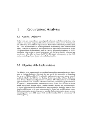
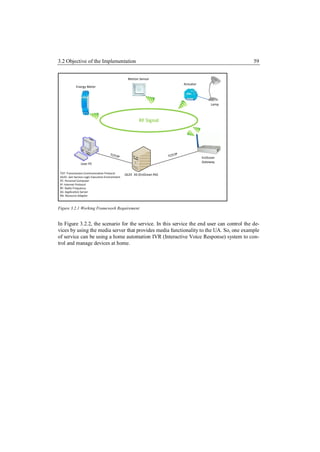
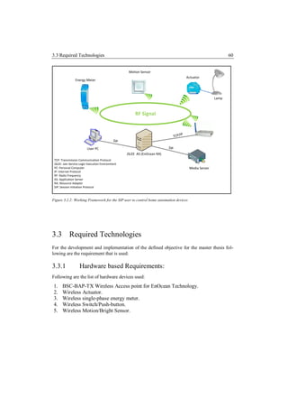
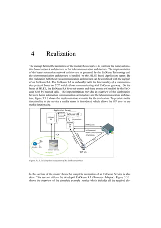
![4.1 Installing Mobicents Application server 63
ments. After deploying the EnOcean RA, the SIP RA and the EnOcean SBB, the connection
between the EnOcean gateway and the AS is established. The control channel between the
AS and the MS is also created during the time of deployment.
Now, the SIP UA, makes a SIP call to the AS. The handling of control channel and the SIP
call flow is done by the SIP RA. The SIP RA fires events to the EnOcean SBB; the EnOcean
SBB calls back a method to utilize the event. A RTP flows between the UA and the MS
which makes it possible to play a file uploaded on the MS. This file is an announcement call.
The UA presses “1” on his or her SIP based equipment and another announcement call is
heard and simultaneously a telegram message is sent. The EnOcean RA fires an event to the
EnOcean SBB which utilizes this event on a method and sends a telegram message to the
EnOcean gateway. On the bases of [Eepv2], the EnOcean gateway reads this telegram mes-
sage. The telegram message is send to the actuator to turn the light “on”; this is send over the
RF signal.
4.1 Installing Mobicents Application server
Mobicents is an open source VoIP (voice over Internet Protocol) platform which indulges in
bringing several kinds sub-projects to integrate with each other. Overtime the Mobicents
developing community has expanded which makes it possible for developers and researcher
enhance their skills. The Mobicents Application Server is basically developed over the
JBOSS architecture. In other sense it is a JBOSS server which is enhanced with the function-
alities related to the JSLEE architecture.
To install the Mobicents Application following are the initial requirements:
1) JDK (Java Development Kit) version 5 or even higher.
2) Eclipse IDE which also consists of an EclipSLEE plug-in, the EclipSLEE plugin
enables the developer to develop JSLEE projects much more conveniently. It is an
IDE specifically for the JSLEE developers for more information see [Mobi1].
3) An Eclipse plug-in for ANT is also required which enables the developer to package
and then also to deploy the deployment unit as described in [Jain].
4) After this installation, the mobicents can be downloaded from the mobicents web-
site [Mobi]. The downloaded folder consists of various service examples and re-
source adaptor examples based on various service logics and communication proto-
cols respectively.
5) The step is to set up the path variable specifically JBOSS_HOME to the path of the
JBOSS bin folder and also the path variable of the JAVA_HOME to the path of the
Java bin folder. However in the newer version Mobicents 2.4.1 this is not required.
6) Install SVN (Subversion) as a software tool as a plug-in on eclipse, this will allow
the developer to access the open source mobicents based services and resource
adaptors. For more information about SVN see [Subv].](https://image.slidesharecdn.com/masterarbeitchandpiyush-111025052413-phpapp01/85/Master-Arbeit_Chand-_Piyush-63-320.jpg)
![4.2 Installing Wireshark 64
After, the above mentioned steps, the developer can use eclipse IDE to develop JSLEE based
services and resource adaptors.
4.2 Installing Wireshark
Wireshark is a very useful tool to computer networks in both wired environment and wireless
environment. It is an open source specifically developed for computer networks specialist
and developers to understand the behaviour of the network based on the traces of the net-
work. It gives the user in-depth information of the network layer at all the seven layers from
the physical layer to the application layer. It is very useful tool for network troubleshooting,
analysis, software and communications protocol development. There are numerous tutorials
on the website which provides information about the using of wireshark effectively. For
more information about wireshark see [Wire].
Wireshark can be downloaded from [http://www.wireshark.org/download.html].
For windows an executable file as a windows installer can be downloaded, the in-
staller can be both 32 bits and 64 bits.
For linux it can be installed by command line using apt-get install wireshark
In Java Programming language, thread is a sequential path of code execution within a pro-
gram. Each thread has its own local variables, program counter and lifetime. In single
threaded runtime environment, operations are executes sequentially i.e. next operation can
execute only when the previous one is complete. It exists in a common memory space and
can share both data and code of a program. For more information about threading, please
refer to [Multi].
4.3 EnOcean Resource Adaptor
In this section of the implementation and realization a detailed view of the EnOcean Re-
source Adaptor is provided. This is the major part of the research work. As, described earlier
a resource adaptor defines an API and a behavioural contract that SBBs use to interact with a
Resource. Resource adaptor types are independent of a particular Resource Adaptor imple-
mentation, allowing development of SBBs that can use multiple different implementations of
the same resource adaptor type.
The EnOcean Resource Adaptor is the logical concept which makes it possible to integrate
the EnOcean gateway to the AS (Application Server). Broadly the EnOcean resource adaptor
can be divided into three modules:](https://image.slidesharecdn.com/masterarbeitchandpiyush-111025052413-phpapp01/85/Master-Arbeit_Chand-_Piyush-64-320.jpg)
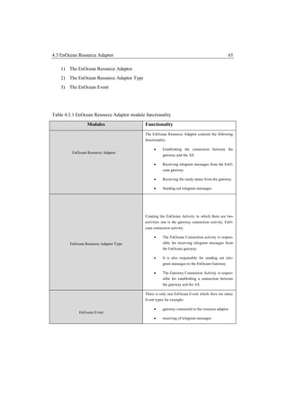
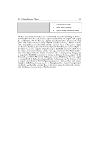
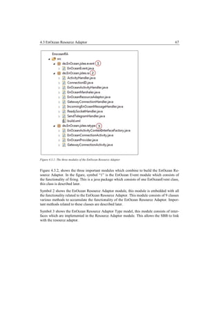
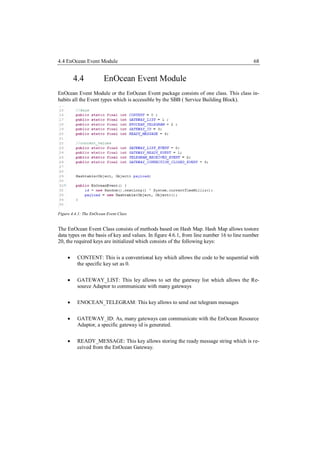
![4.5 EnOcean Resource Adaptor Module 69
From line number 23 to 26, the specific values which are as follows:
GATEWAY_LIST_EVENT,
GATEWAY_READY_EVENT,
TELEGRAM_RECEIVED_EVENT,
GATEWAY_CLOSE_EVENT
All the above mentioned values are set which can be stored as a hash map at line number 29
which allows the keys and values to be stored as a payload.
4.5 EnOcean Resource Adaptor Module
This module consists of all the functionality of the resource adaptor. The module consists of
9 main classes which allow the Resource adaptor to communicate with the EnOcean Gate-
way as per the specification of the ports mentioned in chapter number 2.1.5. The EnOcean
Resource is further modulated to basically three levels which are the following:
1) The EnOcean Resource Adaptor, this sub module contains all the functionality of a
conventional resource adaptor which follows the life cycle. Chapter 2.3.5 describes
the main functionality of a conventional resource adaptor.
2) The Activity handler, which allows the EnOcean Resource Adaptor to utilize the
methods and the objects generated from the activity handler. In the EnOcean Re-
source, there are basically two levels of activity handlers. One is the Gateway Con-
nection handler and the other one is the EnOcean Activity Handler. Both of these
handlers are programmed in a way to handle the threads as these threads are used to
handle connections to the gateway on specific ports which is mentioned in chapter
2.1.5.
3) The third sub-module is the thread classes, these classes are simple threads which
start at specific events. For example, sending telegram message or wiating for in-
coming telegram messages.
Table 4.5.1 The EnOcean Resource Adaptor Module and functionality
Class names and important methods Functionality
EnOcean Resource Adaptor Class
This class is based on the Specification [Jain], it
1. setResourceAdaptorContext( ) follows the mandatory model defined by [Jain].
The mandatory methods defined by [Jain] are 1-13,
2. unsetResourceAdaptorContext( )
which basically follow to life-cycle models; one is the](https://image.slidesharecdn.com/masterarbeitchandpiyush-111025052413-phpapp01/85/Master-Arbeit_Chand-_Piyush-69-320.jpg)
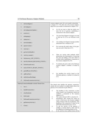
![4.5 EnOcean Resource Adaptor Module 71
sockets at (7).
IncomingEnOceanMessageHandler extends Thread This thread class provides the functionality to the
server to receive incoming telegram messages from
Class the EnOcean gateway.
1. run( ) This class handles the functionality of in-
coming EnOcean Telegram messages from
2. readIncomingEnOceanMessage() the EnOcean gateway to the EnOcean Re-
source Adaptor. This class opens a port for
3. FireEnOceanEvent( ) the telegram messages to be received in the
run method(1).
4. close( )
To allow the resource adaptor to receive
incoming EnOcean Message the method is
invoked at (2).
At (3) an event is EnOceanEvent is fired
which is handled by the resource adaptor
class.
In the end the thread is closed (4)
ReadySocketHandler extends Thread Class This class initiates the ready status of the EnOcean
gateway.
1. run( )
Initially the thread starts which opens port
2. close( ) 2003 for the receiving the ready status
string from the EnOcean gateway at (1).
3. readIncomingReadyMessage()
A close method is invoked if the socket is
to be closed (2).
For receiving the ready status string the
readyIncomingReadyMessage method is
invoke which allows application server to
receive the ready string from the gateway
(3).
SendTelegramHandler extends Thread Class This class starts a thread which consists of the func-
tionality to send out telegram messages to the gate-
1. setEnOceanTelegram( ) way.
Initially to send out telegram messages the
2. run( ) EnOceanTelegram is set which consists
the telegram at (1).
3. close()
Initially the run method is invoked which
opens port 2005 to send out telegram mes-
sages to the gateway at (2).
In the end the socket is closed at (3).
EnOceanActivityHandler extends Thread Class This class is a handler thread which handles the
EnOcean activity as mentioned in [Jain].
1. run ( )
Initially the run method is invoked to start
2. getActivityID( ) the thread, this method starts the incomin-
gEnOceanMessage thread as mentioned](https://image.slidesharecdn.com/masterarbeitchandpiyush-111025052413-phpapp01/85/Master-Arbeit_Chand-_Piyush-71-320.jpg)
![4.6 EnOcean Activity & SIP Activity 72
3. getEnOceanActivity( ) above in this table and also the sendTele-
gramHandler thread is instantiated, the
4. closeSockets( ) message containing a specific port no. is
sent on which the telegram messages are
received(1).
5. close( )
As per the specification of [Jain], an Ac-
6. checkReadyStatus( )
tivity with an ID is get at (2).
7. sendEnOceanTelegram( )
To get the activity a method is created at
(3), this allows resource adaptor to get the
EnOcean Activity which handling the
functionality.
A close method is created which allows
the resource adaptor to close the socket(4).
To check the ready status of the gateway a
method as checkReadyStatus is created
which is invoked whenever the status of
ready is to initialised at (6).
In the end the sendEnOceanTelegram
method is invoked which allows the EnO-
cean resource adaptor to send out telegram
messages to the gateway(7).
4.6 EnOcean Activity & SIP Activity
The EnOcean Activity and the SIP Activity are important logic for handling the SIP resource
adaptor and the EnOcean resource adaptor with the EnOcean SBB. Figure 4.6.1 shows the
implementation of the SIP RA and the EnOcean RA. The EnOcean SBB utilizes the EnO-
cean Activity and the SIP activity over the Activity Context Interface.](https://image.slidesharecdn.com/masterarbeitchandpiyush-111025052413-phpapp01/85/Master-Arbeit_Chand-_Piyush-72-320.jpg)
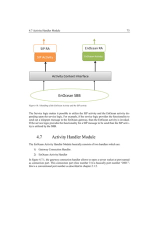
![4.7 Activity Handler Module 74
Figure 4.7.1: Gateway Connnection handler class
In this class a server socket is opened on a connection Port. This connection port is 2001
which allows the gateway to establish a connection to the Server. The developed class is
based on the BSC-BAP Gateway API, which is mentioned in chapter 2.1.5. In the figure
4.7.1, at line number 43 a while loop is implemented which makes it possible for the server
to wait for other gateways to establish a connection. At line number 50, the connection is
accepted which makes it possible for the gateway to establish a TCP [793] connection to the
EnOcean Resource Adaptor. Line number 57 to 61, describes the mentioned IP address on
which the connection is established.
The EnOcean Activity Handler is shown in figure 4.7.2 in this class rest of the important
ports of the Gateway are utilized. This allows the resource adaptor to communicate with
gateway. In this class three threads are started, the first one is the incomingEnOceanMes-](https://image.slidesharecdn.com/masterarbeitchandpiyush-111025052413-phpapp01/85/Master-Arbeit_Chand-_Piyush-74-320.jpg)
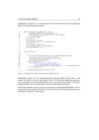
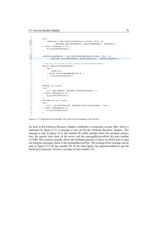
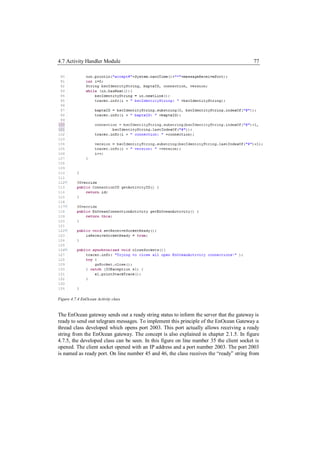
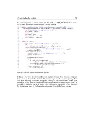
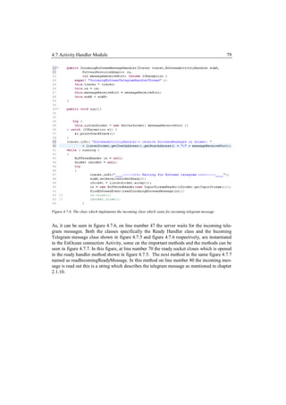
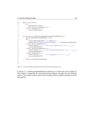
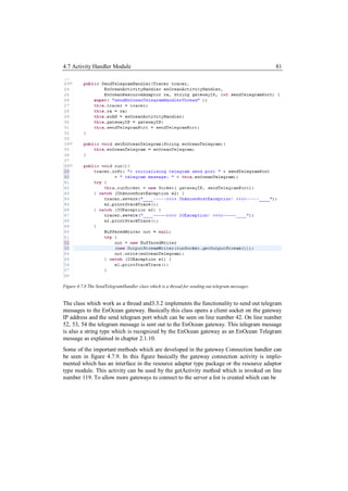
![4.7 Activity Handler Module 82
Figure 4.7.9 Message sent out by the server after opening port 2001
seen on line number 114, figure 4.7.9. The close method is invoked on line number 124 to
close the gateway connection handler thread.
EnOcean Resource Adaptor descriptors:
To make sure the JSLEE architecture can realize the important activities and activity context
interface, some convention are followed which are described in [Jain], in much detailed. The
descriptor logic in JSLEE makes it possible for the JSLEE to know how to use the specific
class in the context of the service. Figure 4.7.10, actually shows the jar xml which depicts
the descriptor of the EnOcean resource adaptor.](https://image.slidesharecdn.com/masterarbeitchandpiyush-111025052413-phpapp01/85/Master-Arbeit_Chand-_Piyush-82-320.jpg)
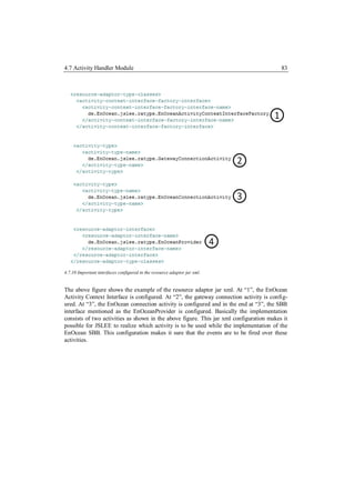
![4.8 EnOcean Service Building Block(SBB) 84
4.8 EnOcean Service Building Block(SBB)
The EnOcean SBB provides the functionality of the EnOcean Service logic which is basi-
cally using two resource adaptors one is the SIP resource adaptor and the other one is the
EnOcean resource adaptor. Figure 4.8.1 shows the EnOcean Service Module
Figure 4.8.1: EnOcean SBB Module
To provide a much detailed view of the functionality within the classes, the table 4.8.1 shows
a list of methods and there functionality in respect to the methods mentioned in the module.
The explanation of the modules is sequentially order with respect to the functionality sequen-
tial number
Table 4.8.1 EnOcean Service module and functionality
Module Functionality
EnOcean Service class 1. Initially in the SBB context all the event lookups are
initialzed which includes the service activity factory as
1. setSbbContext()
mentioned in [Jain], the naming facility as mentioned in
2. unsetSbbContext() [Jain] is initialized, the SBB interfaces for both EnO-
cean Resource Adaptor and the SIP Resource Adaptor
3. sbbActivate() is also initialized as an event lookup.
4. sbbCreate() 2. The service activity factory and the naming facility are
set to null basically again initialize due to the JSLEE
5. sbbLoad()
convention.
6. sbbPassivate()
3-8. The conventional SBB life cycle methods are followed
7. sbbPostCreate() which handles the SBB objects.
8. sbbRemove() 9. On this method the service is started which basically
utilizes two activities; one is the SIP resource adaptor
9. onStartService()
activity to establish the control channel between the
10. onSuccess() application server and Media server. The other activity
is to establish the connection between the gateway and
11. onInvite( )
the AS. A SIP INVITE is created which is send out to
the MS, the MS sends an ACK back to the AS which is
received on onSuccess.](https://image.slidesharecdn.com/masterarbeitchandpiyush-111025052413-phpapp01/85/Master-Arbeit_Chand-_Piyush-84-320.jpg)
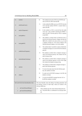
![4.8 EnOcean Service Building Block(SBB) 86
3. setEnOceanActivity( ) 3-4. These methods store the EnOcean Activity in a hash map
which can be set within the SBB and also get within the
4. getEnOceanActivity( )
SBB on some Event.
5. setSubscriberDialog( )
5-6. Both of these methods store the subscriber dialog between
6. getSubscriberDialog( ) the UAC and the AS.
7. setDialogCseq( ) 7-8. To store the dialog, every generated Cseq has to be stored
which is stored as a hash map between the UAC and the
8. getDialogCseq( ) AS.
9. setDialogServerTransaction( ) 9-10. The server transaction dialogs is also stored as a hash
10. getDialogServerTransaction( ) map, again in a set method and get method which are in-
voked in the SBB on an event.
Figure 4.8.2 Initialization done in the SBB
Some of the important methods which provide the EnOcean SSB to provide the required
service are described in more detail. In figure 4.8.2, the important interfaces as mentioned in
[Jain] are initialized. This includes the SIP RA and the EnOcean RA, from line number 179](https://image.slidesharecdn.com/masterarbeitchandpiyush-111025052413-phpapp01/85/Master-Arbeit_Chand-_Piyush-86-320.jpg)
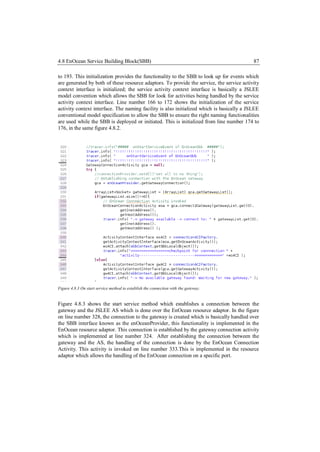
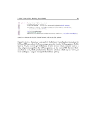
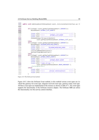
![4.8 EnOcean Service Building Block(SBB) 90
Figure 4.8.6 SBB jar xml syntax for the EnOcean Event.
Figure 4.8.6, shows the EnOceanSbb jar xml, which actually shows the configuration of the
EnOcean event descriptor, this is a defined convention mention in [Jain], by which the EnO-
cean SBB knows which type of Event is to be utilized from JSLEE while developing the
service logic.
Figure 4.8.7 SBB jar xml showing the binding of the Enocean RA
Figure 4.8.7; show the jar xml which binds the EnOcean Resource adaptor over the Activity
context interface to the SBB. This is again a convention followed in [Jain], which gives pro-
cides the necessary parameters to define the SBB jar xml. This configuration provides the
information to JSLEE that this is the specific EnOcean Resource Adaptor which is to be
utilized by the EnOcean SBB. So, when the service is deployed the SBB subscribes for an
event that is fired on a RA activity to this resource adaptor for receiving events which is then
used in the service logic.](https://image.slidesharecdn.com/masterarbeitchandpiyush-111025052413-phpapp01/85/Master-Arbeit_Chand-_Piyush-90-320.jpg)
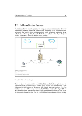
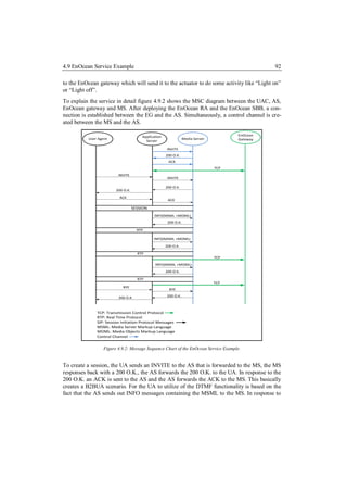
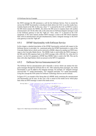
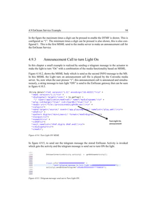
![4.9 EnOcean Service Example 95
4.9.4 Announcement Call to turn Light Off
In this chapter, a small example is realized, for turning off the light with a backend function-
ality of the media server. The handling is nearly the same as to turn the light on but the tele-
gram messages changes based on the information in [Eepv1]. Similarly as mentioned in
chapter 4.9.2, the MSML based announcement to turn the light OFF is shown in figure 4.9.6.
In this figure the MSML body consists the turn light off announcement call file. This file is
played back to the UA, when and INFO message is send to the MS. The INFO message body
contains the MSML body which can be seen in figure 4.9.6.
Figure 4.9.6 MSML body to turn light off
Similarly, to send out the EnOcean telegram message to turn light OFF can be seen in figure
4.10.5. In this figure the EnOcean Activity is initially invoked that is stored in the service
activity context interface. After getting the activity, the telegram message to turn the light off
is send the EnOcean gateway which eventually makes the light “OFF”. The telegram mes-
sage is basically created from the specification mentioned in [Eepv1].
Figure 4.9.7 Telegram message send to turn light off.](https://image.slidesharecdn.com/masterarbeitchandpiyush-111025052413-phpapp01/85/Master-Arbeit_Chand-_Piyush-95-320.jpg)

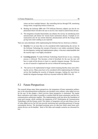
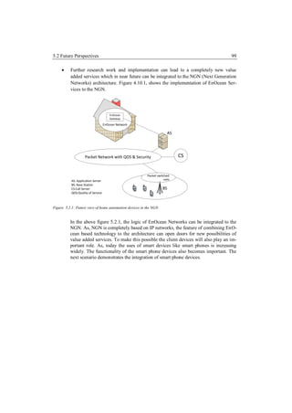
![5.2 Future Perspectives 100
Figure 5.2.2: Abstract view of various client handling home automation gateway.
The figure 5.2.2 provides an abstract view of anroid client, I-phone client with a
smart phone interface and the laptop/PC client with a web browser interface. All
these devices can be brought together to control EnOcean devices. So, the UA will
be a based on an anroid client or any other smart phone and will utilize the func-
tionality of the AS. As, currently the back end functionality is taken care by the AS,
developing various application on the client side that will be the front end can mo-
tive the value added service scenario for the EnOcean Service.
The implementation of the master thesis work provides various aspects of imple-
menting this service in the customer oriented manner. This makes the handling of
the SBB quite significant. As, the Enocean resource provides the functionality to es-
tablish and handle connection with many gateways. The functionality of sending
and receiving telegram message becomes a concern. This can be handled by intro-
ducing the concept of a database. In JSLEE there is a resource adaptor named JDBC
(Java Database Connectivity), JDBC is a database interface for java platforms. The
JDBC RA can provide an interface to a database and the handling of the queries as
mentioned in [Jdbr] can be done by the JDBC RA. The queries are based on SQL,
so any SQL based database can be integrated. This follows to enhance the service
by storing the user specific information and then retrieving the required information
when necessary. In respect to EnOcean Service, some functionality can be stored,
for example a list of EnOcean telegram messages used by a specific user or a spe-
cific EnOcean gateway ID which will initiate the specific telegram messages.](https://image.slidesharecdn.com/masterarbeitchandpiyush-111025052413-phpapp01/85/Master-Arbeit_Chand-_Piyush-100-320.jpg)
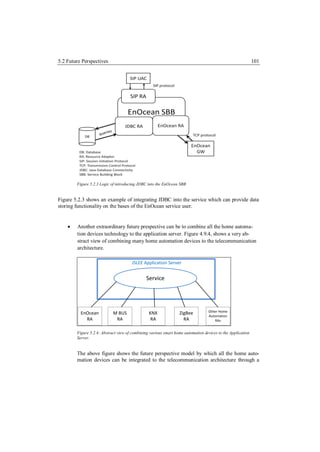
![5.2 Future Perspectives 102
Resource Adaptor. The RA will have the ability to communicate through standard-
ized smart home automation communicating protocols.
After working on the master thesis research project, mentioning about the importance of the
research project as a whole becomes very important. The EnOcean technology is being
adopted quite significantly throughout the world. The technical aspects of the EnOcean
Technology are standardized for home automation. Plenty of research work is being done to
make the EnOcean Technology devices much more intuitive to the home automation world.
The introduction of new Standard based on [Eepv2], provides more added feature to the
EnOcean telegram message that shows the existence of importance in this home automation
sector. For making a complete controlling and monitoring platform ICT will play a major
part. This master thesis work gives a foundation to combine both the telecommunication
architecture and the home automation architecture. As, mentioned the importance of home
automation devices in this paragraph, I believe that more research work should be followed
to combine ICT and the Energy world together for a complete smart grid and ubiquitous
experience.](https://image.slidesharecdn.com/masterarbeitchandpiyush-111025052413-phpapp01/85/Master-Arbeit_Chand-_Piyush-102-320.jpg)
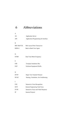
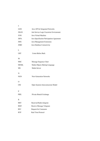

![7 References
[3261] Rosenberg, J.;Schulzrinne ,H.;Camarillo, G.;Johnston, A.;Peterson,
J.;Sparks, R.;Handley, M.;Schooler, E.;“SIP: Session Initiation Proto-
col”, RFC 3261, IETF, June 2002.
[3665] Johnston, A.; Donovan, S.; Sparks, R.; Cunningham, C.; Summers, K.:
“Session Initiation Protocol (SIP) Basic Call Flow Examples”, RFC
3665, IETF, December 2003.
[793] Robert E. Kahn.; Vinton G. Cerf.; “Darpa Internet Program Protocol
Specification”, RFC 793, IETF, September 1981.
[1180] Socolofsky T.; Kale C.; “A TCP/IP Tutorial”, RFC 1180, IETF, Janu-
ary 1991.
[2616] Fielding, R. ; Irvine, UC; Gettys J.; Mogul J.; Frystyk H.; Masinter
L.; Leach P.; Berners-Lee T.; “Hypertext Transfer Protocol --
HTTP/1.1”, RFC 2616, IETF, June 1999.
[5707] Saleem A.; Xin Y.;Sharrat G.; “Media Server Markup Lan
guage(MSML)”, RFC 5707 February 2010.
[Bscb] BSC-BAP-TX Wireless Access point: BSC-BAP Datasheet, issue date
21.08.07, available at
http://www.enoceanalliance.org/uploads/tx_f03enocean/bsc_Produktdat
enblatt-BAP.pdf
[Bapi] BSC-BAP-TX API Manual by BSC Computer Gmbh.
[Conv] Convedia Media Server: MSML 1.1 Interface Refernce issued date
December 2009.](https://image.slidesharecdn.com/masterarbeitchandpiyush-111025052413-phpapp01/85/Master-Arbeit_Chand-_Piyush-106-320.jpg)
![[Enoc1] EnOcean- the originator of patented energy harvesting wireless tech-
nology, available at http://www.enocean.com/en/company-profile/
[Enoc2] ENOCEAN DOLPHIN - The platform for Energy Harvesting wireless
sensor technology, available at
http://www.enocean.com/fileadmin/redaktion/pdf/press/enocean_dolphi
n_EN.pdf
[Enoc3] Energy Efficiency and flexibility enabled by EnOcean, available at
http://www.enocean.com/fileadmin/redaktion/pdf/press/enocean_hvac_
en.pdf
[Enoc4] EnOcean Technology- Energy Harvesting Wireless, Issued on July
2011, available at
http://www.enocean.com/fileadmin/redaktion/pdf/white_paper/WP_En
Ocean_Technology_en_Jul11.pdf
[Enoc5] Wireless Sensor Solutions for Home & Building Automation, issued on
August 10, 2007, available at
http://www.enocean.com/fileadmin/redaktion/pdf/white_paper/wp_sens
ors_for_automation.pdf
[Enoc6] EnOcean: Smart Ack Bi-directional Thermostat with display, issue date
july 2011, available at
http://www.enocean.com/fileadmin/redaktion/pdf/app_notes/AN501_S
MART_ACK.pdf.
[Enoc7] EnOcean: Remote Management 1.7, issued date December 2010, avail-
able at
http://www.enocean.com/fileadmin/redaktion/pdf/tec_docs/RemoteMan
agement.pdf.
[Enoc8] EnOcean Radio Protocol, issued date February 8, 2011, available at
http://www.enocean.com/fileadmin/redaktion/pdf/tec_docs/EnOceanRa
dioProtocol.pdf](https://image.slidesharecdn.com/masterarbeitchandpiyush-111025052413-phpapp01/85/Master-Arbeit_Chand-_Piyush-107-320.jpg)
![[Elta1] Wireless Actuator (FSR61NP): The Eltako Wireless System, 2011,
available at
http://www.eltako.com/fileadmin/downloads/en/_catalogue/wireless_sy
stem_high_res.pdf
[Elta2] Wireless single-phase energy Meter (FWZ12-16A): The Eltako Wire-
less System, 2011, available at
http://www.eltako.com/fileadmin/downloads/en/_catalogue/wireless_sy
stem_high_res.pdf
[Elta3] Wireless switch/ Push-button (FT4F): The Eltako Wireless System,
2011, available at
http://www.eltako.com/fileadmin/downloads/en/_catalogue/wireless_sy
stem_high_res.pdf .
[Elta4] Motion/Brightness sensor (FBH55): The Eltako Wireless System, 2011,
available at
http://www.eltako.com/fileadmin/downloads/en/_catalogue/wireless_sy
stem_high_res.pdf
[Eepv1] EnOcean Equipment Profiles (EEP) V2.0, July 2009, available at
http://www.enoceanalliance.org/fileadmin/redaktion/enocean_alliance/
pdf/EnOcean_Equipment_Profiles_2.0.pdf
[Ecli] Eclipse Development Platform, Available for download at:
http://eclipse.org/ [Accessed 24 June 2011].
[Jain] Ferry D.: “JAIN SLEE (JSLEE) Specification 1.1, Final release”, JSR
240, Sun Microsystems Inc., 2008.
[Jain3] Jain an Java in Communication, issued in march 2004, available at
http://java.sun.com/products/jain/reference/docs/Jain_and_Java_in_Co
mmunications-1_0.pdf
[Jain4] JSLEE and the JAIN initiative, available at
http://java.sun.com/products/jain/.](https://image.slidesharecdn.com/masterarbeitchandpiyush-111025052413-phpapp01/85/Master-Arbeit_Chand-_Piyush-108-320.jpg)
![[Jdbr] Mobicents Jain Slee JDBC Resource Adaptor User Guide , by Eduardo
Martin, dated 2010, available at http://docs.jboss.org/mobicents/jain-
slee/2.4.1.FINAL/resources/jdbc/user-guide/en-US/html/.
[Mobi1] Installing Mobicents JSLEE, available at
http://docs.jboss.org/mobicents/jainslee/2.4.1.FINAL/tools/eclipslee/use
r-guide/en-US/html/install.html
[Mobi2] Mobicents Application server, available at
http://sourceforge.net/projects/mobicents/files/Mobicents%20JAIN%20
SLEE%20Server/
[Mobi3] Ivanov Ivelin, Mobicents JSLEE: for the people, by the people, issued
on 14th march 2006 available at
http://today.java.net/pub/a/today/2006/03/09/mobicents-jslee.html
[Mmjt] Michael Maretzke, Java Telecommunication Application Server Tech-
nology Comparison, published on 29th july 2008, available at
http://www.maretzke.de/pub/whitepapers/telcoappserver_2008/Position
ing_TelcoApplicationServer_Technologies_MiMa_v1.0_20080729.pdf
[Multi] MultiThreading, available at
http://www.tutorialspoint.com/java/java_multithreading.htm
[Sunj] JSLEE tutorial Serving the developer community, Open Cloud, 2003,
available at http://java.sun.com/products/jain/JAIN-SLEE-Tutorial.pdf](https://image.slidesharecdn.com/masterarbeitchandpiyush-111025052413-phpapp01/85/Master-Arbeit_Chand-_Piyush-109-320.jpg)
![[Subv] Open source software engineering tool subversion, available at
http://subversion.tigris.org/.
[Sipc] Bringing Telephony Features into SIP Networks with Back To Back
User Agent, available at
http://www.sipcenter.com/sip.nsf/html/Bringing+Telephony+Features+i
nto+SIP+Networks+with+Back+To+Back+User+Agent.
[Tcmu1] TCM 120 Transceiver Module User Manual V1.53, August 2008, at
http://www.enocean.com/en/enocean_modules/TCM_120_User_Manua
l_V1.53_02.pdf
[ Tsac ] Tanenbaum S. A.; Computer Networks, fourth edition, ISBN: 0-13-
066102-3, published on March 17, 2003.
[Uocl] University of Otaga, Open Cloud Limited: JAIN SLEE Fundamentals.
http://www.jainslee.org/slee/fundamentals.html,
[Wire] Wireshark website, available at
http://www.wireshark.org/download.html. (accessed september)](https://image.slidesharecdn.com/masterarbeitchandpiyush-111025052413-phpapp01/85/Master-Arbeit_Chand-_Piyush-110-320.jpg)


This master's thesis explores integrating a home automation architecture based on EnOcean technology with a telecommunications architecture. It develops an EnOcean resource adaptor for a JAIN SLEE application server to communicate with an EnOcean gateway. It then develops a JAIN service that allows a SIP user agent to control and monitor home automation devices like lamps, motion sensors, and energy meters through an interactive voice response system. The goal is to demonstrate a method for remote management and control of EnOcean-based smart home devices through a telecommunications network and SIP.


![[Tobias herbig, franz_gerl]_self-learning_speaker_(book_zz.org)](https://cdn.slidesharecdn.com/ss_thumbnails/tobiasherbigfranzgerlself-learningspeakerbookzz-150520140217-lva1-app6892-thumbnail.jpg?width=640&height=640&fit=bounds)


