Downloaded 17 times

![Major Project: Play & Record with Dtmf Service based on JSLEE 5
application server provides a high throughput, low latency event processing application
environment. JSLEE (Jain Service Logic Execution Environment) is the Java standard for SLEE.
JSLEE is designed to allow implementations of the standard to meet the stringent requirements of
communications applications, such as network signalling applications. The JSLEE specification
is designed so that implementations can achieve scalability and availability through clustering
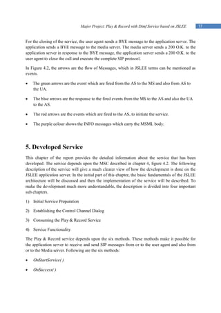
architectures. Below, in figure 3.1.1, the architecture of the JSLEE can be seen. [1]
Figure 3.1.1 JSLEE Architecture [1]
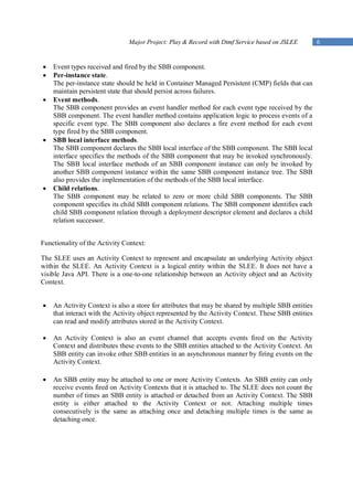
In this architecture, JSLEE consists of four main areas: management, framework, resource
adaptors, and the Component model. The management entities allow the whole JSLEE
environment to be managed through JMX-Mbeans or Jopr i.e. an enterprise management solution
for JBoss middleware projects and other application technologies. The various entities in the
framework support the business logic implemented in distributed components, the so-called
service building blocks, or SBB. The trace entity allows a centralized and single point for
logging, alarms inform external management systems, timers invoke components in pre-defined
intervals, and profiles provide the business logic with information and data during execution.
Among them, the event router routes incoming and newly created events to previously registered
SBBs (Service Building Block) and resources. The event router is more or less the heart of
JSLEE's event routing system.
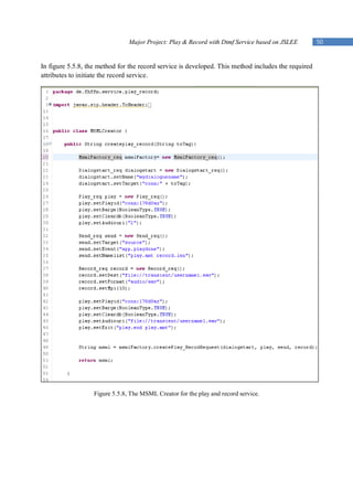
In this architecture, every area (i.e. management, framework, resource adaptors, and the
Component model) has its own importance. From a developer’s point of view the Component
Model which contains the SBB (Service Building Block) is quite significant.
Functionality of a SBB: [2]](https://image.slidesharecdn.com/majorprojectchandpiyush2011-13016628428635-phpapp01/85/Major-Project-Chand-Piyush-2011-5-320.jpg)
![Major Project: Play & Record with Dtmf Service based on JSLEE 7
Whenever any event is fired by the SBB, the SBB is attached to the Activity Context. In this
respect it can be mentioned that the activity context is a main part to initiate the SBB service.
This is a basic concept in the JSLEE architecture, which will be again discussed in the
programming phase of the service.
3.2 Convedia Media Server- 3000
The RadiSys Convedia CMS-3000 media server delivers carrier-class media processing
capabilities for enterprise IP telecommunication services. Increased processing power, including
I/O throughput upgrades, delivers significant performance improvement for Voice XML-based
IVR and messaging applications, while delivering multi-service versatility for numerous
applications including IP PBX, instant video conferencing, IP contact centres, and unified
communication solutions. [3]
Valuable Services related to CMS- 3000:
Tones and Announcements: Audio announcements and ring back tones, Multiple languages
(40+), Variables (e.g. date, time, currency, etc.), Caller–specific announcement volume control.
DTMF: DTMF detection and generation, In band and RFC 2833, Redundant RFC 2833.
Conferencing: Up to 110 3-way conferences, Up to 330 participants per conference mix, N-way
audio mixing, Loudest N mixing and preferred speaker, Independent manual gain, control on all
ports, Automatic Gain Control (AGC), Current speaker notification, Whisper feature,
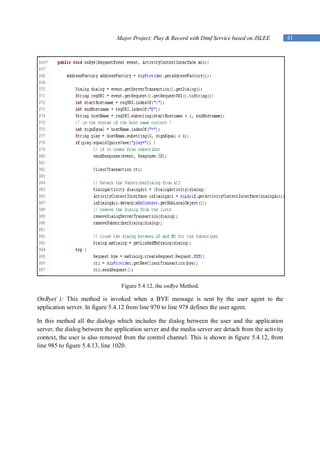
Personalized mixing for each participant (e.g. for complex call centre mixing models, network,
gaming, voice chat, etc.).
Recording and Playback: Audio and video recording / playback VCR Control (pause/resume,
skip forward, skip back) Internal and external storage (NFS/HTTP).
Audio Recording Formats:
.wav (G.711, G.729)
Quick time™ format (G.711)
3GP format (AMR)
RTSP 1.0 support for playback (G.711, AMR)
Voice Quality Enhancements (VQE): Packet Loss Concealment, Noise Gating, Noisy line
detection, VQE Statistics, Acoustic Echo Cancellation (AEC), and Noise Reduction.
Stream Connection: CALEA/Lawful intercept support for video and audio streams, Packet
forking, switching, and media replication (fan out).
Video: Video announcements and ring back tones Video recording and playback Interactive
Voice and Video Response (IVVR) Video text overlay, Voice–activated video switching (video
Conferencing), Continuous presence video conferencing.
Fax: Fax Detection & Notification, Embedded Fax Server (Send/Receive), T.38 or G.711 (T.30
Pass-through), TIFF Fax Storage Format.](https://image.slidesharecdn.com/majorprojectchandpiyush2011-13016628428635-phpapp01/85/Major-Project-Chand-Piyush-2011-7-320.jpg)
![Major Project: Play & Record with Dtmf Service based on JSLEE 8
Speech: Text-to-speech (TTS), Automatic speech recognition (ASR), Speaker verification,
MRCP v1.0 and v2.0.
Among these services, the main implementation of the service will be upon the Recording, Play
Back and also the DTMF.
3.3 MSML (Media Sessions Mark-up Language)
The Media Sessions Mark-up Language (MSML) is an XML (Extension Mark-up Language)
language used to specify and change the flow of media streams within a media server. MSML is
designed for manipulating media services offered by the media server to established media
sessions (established using SIP). MSML specifies how media sessions on the media server
interact, and controls and invokes media services on the media server.
For example, MSML can be used to create conferences and join sessions into conferences.
MSML can also be used with MOML (Media Objects Markup Language) to interact with
individual users or with groups of conference participants, for example applying IVR operations,
called “dialogs,” to sessions or conferences. Using MSML, it is also possible to control advanced
conferencing features on a media server, to modify media while a session is in progress, and to
perform advanced session manipulation such as personalized mixing.
MSML transactions are originated by application domain events. These events can be
independent of any media or user interaction. For example, an application may play an
announcement to a conference warning that its scheduled completion time is approaching.
MSML is designed to be used with other languages. For example, MSML does not set up or tear
down sessions. Instead, MSML uses a transport protocol such as SIP for that purpose. Various
protocols and languages are used to meet the requirements of media applications, so MSML has
been designed to be language-neutral, independent of its transport, and to use either one or many
transport channels. Similarly, MSML does not directly manipulate media resource objects.
Instead, MSML can be used to invoke media processing languages such as Media Objects Mark
up Language.
MSML does not directly constrain the media processing language. However, the current
implementation of MSML on the Convedia Media Server supports only MOML as a media
processing language. While MSML addresses the relationships of media streams (in, for example,
simple and advanced conferencing), MOML is an XML language that addresses the control and
manipulations of media processing operations, such as announcement, IVR, play and record,
AST/TTS, fax, and video. Together, MSML and MOML form general-purpose media server
control protocol architecture. [3]
DTMF Detection, Collection, and Generation
The media server detects, collects, and generates DTMF signals. These can be in band audio
DTMF tones or out-of-band RFC 2833 telephone-events.
DTMF collection can include any of a number of mechanisms supported by the control
protocol/language used by the control agent, including collection grammars. For example, the
control agent can use Speech Recognition Grammar Specifications (SRGSs), which are built-in](https://image.slidesharecdn.com/majorprojectchandpiyush2011-13016628428635-phpapp01/85/Major-Project-Chand-Piyush-2011-8-320.jpg)
![Major Project: Play & Record with Dtmf Service based on JSLEE 9
language grammars dedicated to specific tasks such as digit sequences or phone numbers, or digit
maps as defined by RFC 3435. The media servers also support long digit detection.
In addition to collection grammars, the media server supports a DTMF type-ahead buffer, as well
as the following optional capabilities:
Dynamically specified first-digit timers
Dynamically specified inter-digit timers
Dynamically specified extra-digit timers
Definition of a special termination key, such as “#”
The way DTMF is collected depends on media negotiation by the control protocols. For example,
while in band and out-of-band DTMF are supported, only the method negotiated using the control
protocol will be used. This functionality of the DTMF will be used while implementing the
service. [3]
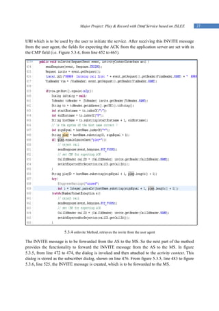
3.4 MSML Control Channel
There are cases where the control agent prefers to set up one or more transport associations
strictly for service control signalling—that is, SIP (Session Initiation Protocol) sessions carrying
MSML and MOML without any associated media stream. To do this, the control agent must still
include SDP in its initial INVITE (otherwise, the media server will initiate an offer instead of
setting up a control channel). [3]
To signal the media server that a control channel is desired. The control agent can do either of the
following:
Figure 3.4.1, shows a call flow setting up an MSML channel strictly for control. Send an
INVITE that contains SDP, but where the SDP does not specify media—it contains no m= line.
This signals the media server that there is no media stream. This does not request a control
channel per se, but the media server understands this as a request to set up a control channel, and
does not initiate an offer/answer sequence. Send an INVITE that contains complete SDP but uses
0.0.0.0 as the connection IP address. In this case, the media server assigns IP/UDP and codec, but
does not send any RTP (Real Time Protocol).](https://image.slidesharecdn.com/majorprojectchandpiyush2011-13016628428635-phpapp01/85/Major-Project-Chand-Piyush-2011-9-320.jpg)
![Major Project: Play & Record with Dtmf Service based on JSLEE 10
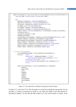
Figure 3.4.1 Call Flow Setting up for a Control Channel [3]
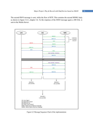
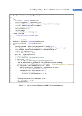
The control channel will be built within the developed service, so as to send MSML as INFO to
the Media Server and then receive a response 200 O.K. from the Media Server.
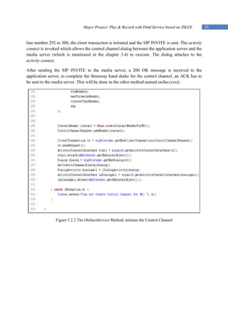
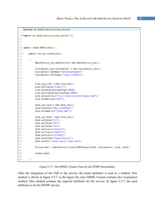
Figure 3.4.1, shows the example of a MSML, which provides the functionality to record and play
the recorded file. These will be sent to the Media Server within a SIP INFO Message.
Figure 3.4.2 MSML Example for Play and Record [3]](https://image.slidesharecdn.com/majorprojectchandpiyush2011-13016628428635-phpapp01/85/Major-Project-Chand-Piyush-2011-10-320.jpg)
![Major Project: Play & Record with Dtmf Service based on JSLEE 11
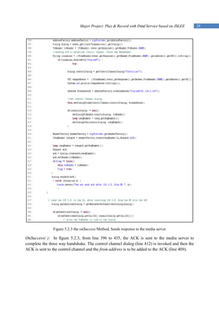
Figure 3.4.2, shows the example of a DTMF functionality based Msml. This will be sent to the
media server.
Figure 3.4.3 MSML Example for DTMF [3]
In both the above mentioned examples you can see, how the MSML and the MOML are bind
together, to make a complete useful snippet which can be used to initiate the response from the
media server.
3.5 SIP (Session Initiation Protocol)
SIP is a protocol for the creation and full control of Multimedia over IP Sessions. SIP fulfils for
Multimedia over IP the same purpose as a signalling protocol in circuit switched
telecommunication (ISDN-DSS1, POTS, SS No. 7). Additional functions of SIP: e.g. short
messaging, state/event monitoring (e.g. monitoring of the online status of a participant) First SIP
specification in 1999 through IETF (Internet Engineering Task Force) in RFC (Request for
Comments) 2543 Realized through the exchange of text-based messages linked to the HTTP
(Hyper Text Transfer Protocol). [5]
Basic functionality of SIP:
SIP serves in the transferring of signalling and transmission information for Voice over IP or
Multimedia over IP Sessions (Real-time communications connections in IP Networks.
Session forms: Point-to-point, conferences with three or more participants.](https://image.slidesharecdn.com/majorprojectchandpiyush2011-13016628428635-phpapp01/85/Major-Project-Chand-Piyush-2011-11-320.jpg)
![Major Project: Play & Record with Dtmf Service based on JSLEE 13
REGISTER: (Registering of an SIP End system of a SIP Registrar Server).
OPTIONS: (Enquiry for features of a SIP End system, no session build up required).
SIP Message Header:
Headers describe each SIP Message, the corresponding SIP Transaction as well as characteristics
of the SIP Network elements. Following are the list of header message, which is part of every SIP
message depending upon the type of message to be sent. [5]
In Figure 3.5.1, a list of used header fields and their characteristics are described.
Figure 3.5.1 Description of the Header field [5]](https://image.slidesharecdn.com/majorprojectchandpiyush2011-13016628428635-phpapp01/85/Major-Project-Chand-Piyush-2011-13-320.jpg)
![Major Project: Play & Record with Dtmf Service based on JSLEE 14
Figure 3.5.2 Example of a header field [5]
In Figure 3.5.2, an example of the SIP Message Header can be seen; in this the fields are filled in
with the associated header field.
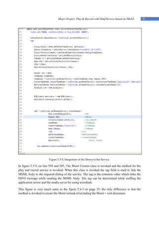
4 Used Practical Framework
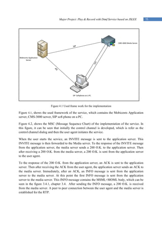
In this part of the report, the used practical framework is described, and also the MSC( Message
Sequence Chart) is discussed with respect to the service that is developed.
Application Server used: Mobicents Media Server, version MMS 2.2.1, it is software
based. It is described in detail in chapter 3.1.
Media Server used: Convedia Media Server, CMS-3000, explained in detail in chapter 3.2
Integrated Development Environment (IDE) used: Eclipse, version- Helios 3.6.2
Network Analyser used: Wireshark. It is a free program for the analysis of network
communication links
SIP Soft Phone used: PhonerLite. It enables your PC to use it for internet telephony VoIP
(Voice over IP).](https://image.slidesharecdn.com/majorprojectchandpiyush2011-13016628428635-phpapp01/85/Major-Project-Chand-Piyush-2011-14-320.jpg)
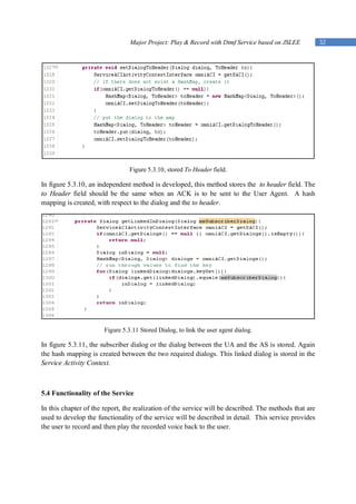
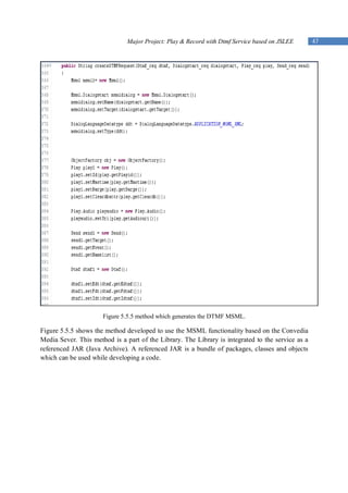
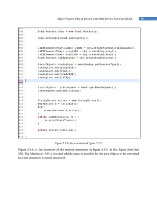
![Major Project: Play & Record with Dtmf Service based on JSLEE 43
The MSML and the MOML are XML schema files which are stored within the CMS-3000
server. These Schema files can be parsed to generate java objects. There are many ways of
parsing the xml schema. The technique that has been used in the development is the JAXB (Java
Architecture for XML Binding). JAXB is basically a parsing technique to convert xml to java
objects and vice versa. Figure 5.5.1, shows the implementation of the JAXB technique. In the
figure it can be seen that the XML Schema is compiled by using a Binding compiler to generate
the required schema derived classes and interfaces.
5.5.1 JAXB API Technique [6].
The JAXB API in the figure 5.5.1 provides the functionality to use the marshalling and
unmarshalling techniques. Unmarshalling an XML document means creating a tree of content
objects that represents the content and organization of the document. Marshalling is the opposite
of unmarshalling. It creates an XML document from a content tree. [6]](https://image.slidesharecdn.com/majorprojectchandpiyush2011-13016628428635-phpapp01/85/Major-Project-Chand-Piyush-2011-43-320.jpg)
![Major Project: Play & Record with Dtmf Service based on JSLEE 53
7. References
[1] Ivelin Ivanov : Mobicents JSLEE for the People, by the People issued on March 14, 2006
available at http://today.java.net/pub/a/today/2006/03/09/mobicents-jslee.html.
[2] JAIN SLEE (JSLEE) 1.1 Specification, Final Release, issued in the year 2008, available at
http://jcp.org/aboutJava/communityprocess/final/jsr240/index.html.
[3] CONVEDIA MEDIA SERVER: MSML 1.1 INTERFACE REFERENCE issued date
December 2009, RELEASE 4.19.
[4] CONVEDIA MEDIA SERVER: MOML 1.0 INTERFACE REFERENCE issued date on
December 2009, RELEASE 4.19.
[5] Prof. Dr.- Ing. Ulrich Trick: Methods, Systems and Networks for Digital Communication,
Lecture on Next Generation Networks, Voice over IP and SIP.
[6] Ed Ort and Bhakti Mehta: Java Architecture for XML Binding (JAXB) issued on March
2003 available at http://www.oracle.com/technetwork/articles/javase/index-140168.html](https://image.slidesharecdn.com/majorprojectchandpiyush2011-13016628428635-phpapp01/85/Major-Project-Chand-Piyush-2011-53-320.jpg)

The document is a major project report on developing a Play & Record with Dtmf service based on JSLEE. It includes an acknowledgment section and outlines the following contents: project goal, structure of the report, theoretical basis on JSLEE, Convedia Media Server 3000, MSML and control channels, the used practical framework, the developed service including functionality and library development/integration, and a conclusion.