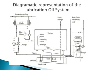
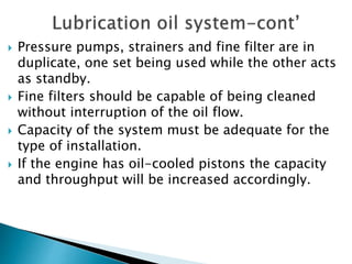
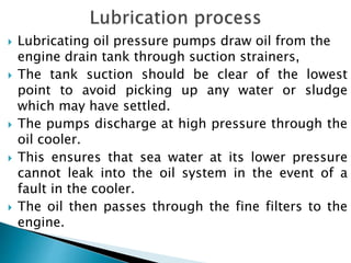
Fuel Oil System
 The ignition quality of fuel is denoted by its
ignition lag period.
 Defined as the relative ease with which the fuel is
ignited and its readiness to burn completely under
engine conditions.
 Measured in terms of Cetane Number.
 It is a straight chain paraffin with good ignition
quality.
 It is arbitrarily assigned a rating of 100 cetane
number.
 It is mixed with alphamethyl-napthalene, a
hydrocarbon with poor ignition quality and
assigned as zero cetane number.
 The cetane number of fuel is the percentage of
volume of cetane present in a mixture with
alphamethyl-napthalene that is matched with the
fuel under test to give the same ignition lag.
 A high Cetane number indicates a short ignition
delay.
 Other measures of ignition quality is Diesel index.
 For residual or blended fuels the ignition quality
can be expressed as:
 CCAI value (calculated carbon aromacity index) or
 CII (calculated ignition index)
 The lower the CCAI value, the better the ignition
quality. A limiting value of 870 is preferred.
 Ignition quality is particularly important for:
 Ease of starting an engine, or
 When operating at reduced power for long periods
 Pp
 It can be improved by:
 Increasing the compression ratio of the engine or
 Pre-heating the scavenge air.
 There will be design or operational limits to these
methods.
 If an engine operates for long periods at reduced
power or speed, the residual heat in the main
components of the combustion chamber will
decrease.
 Causing a lower air temperature after compression.
 This leads to increased ignition delay of injected
fuel and will cause knocking or ‘rough running’ in
the engine.
 This problem can be reduced by the use of VIT to
advance the start of injection, allowing for the
longer delay but maintaining ignition timing and
the same peak pressure.
 VIT is automatically superimposed on the normal
fuel pump setting from the engine governor.
 Additional linkage from the governor will advance
each pump setting over the range of lower speeds.
 Fuel pumps are designed to carry out necessary
adjustment while the engine is running.
 This control can also be manually regulated to
advance normal governor settings if it is known
that fuel with low ignition quality is to be used.
 Built in by shaping the profile of the pump plunger
to give an earlier start of injection at lower fuel
settings.
 Manual adjustment, advancing the timing for low
ignition quality fuel, is fitted in some engines.
 A system by which fuels with low ignition quality
can be burnt smoothly and efficiently, even in
medium or high speed engines.
 A small ‘pilot’ charge of finely atomized fuel is
briefly injected very early during compression.
 This small charge is heated and vaporized, passing
through its delay period and igniting just before
the main charge of fuel is injected.
 Combustion of the pilot charge will cause high
temperature and turbulence in the combustion
space.
 This together with its flame front will cause the
main charge of fuel to ignite and burn smoothly as
it is injected.
 This way, the violent pressure rise usual with these
fuels is avoided.
 Combustion is efficient and the peak pressure is
limited.
1. Twin injection:
 Two separate injectors are fitted to each unit;
both must be correctly timed.
 The pilot injector has fine nozzle holes to
atomize the fuel at a moderate injection pressure
and is timed to commence before the main fuel
charge injection.
 The main injector is situated in a position to give
an effective fuel spray.
 It injects the main, measured charge at normal
fuel injection pressure.
2. Compound injector
 One injector is designed to inject the pilot charge
with fine atomization and must also inject the main
fuel charge.
 To do this it requires variable nozzle holes and a
two stage needle valve lift.
 Fuel pump drive for this system may require
specially shaped cam profiles.
 Fuel injectors
 Fuel pumps
Lubrication Oil System
 Pressure pumps, strainers and fine filter are in
duplicate, one set being used while the other acts
as standby.
 Fine filters should be capable of being cleaned
without interruption of the oil flow.
 Capacity of the system must be adequate for the
type of installation.
 If the engine has oil-cooled pistons the capacity
and throughput will be increased accordingly.
 Lubricating oil pressure pumps draw oil from the
engine drain tank through suction strainers,
 The tank suction should be clear of the lowest
point to avoid picking up any water or sludge
which may have settled.
 The pumps discharge at high pressure through the
oil cooler.
 This ensures that sea water at its lower pressure
cannot leak into the oil system in the event of a
fault in the cooler.
 The oil then passes through the fine filters to the
engine.
 It will be distributed to all bearings, piston cooling,
sprayers, exhaust valve actuators, control systems
etc.
 Used oil drains to the bottom of the crankcase and
passes through strainers by gravity to the drain
tank.
 Drain returns are kept remote from the pump
suction and must be submerged to reduce aeration
and to make a safe seal.
 With oil cooled pistons each piston oil return has
its temperature monitored.
 It then passes through a sight glass before
returning to the crankcase.
 Usually built into the ship’s double bottom.
 It must be surrounded by a cofferdam to prevent
any contamination from leakages.
 It is fitted with an air vent, level measuring gauge
and sounding pipe.
 The Level gauge is centrally positioned to reduce
fluctuation in readings due to pitching and rolling
at sea.
 Tank must be of sufficient size to accommodate
the full charge of oil.
 Its interior surfaces may be coated to prevent
rusting due to condensation on its non-flooded
surfaces.
 The system should also have low pressure, high
temperature and low tank level alarms fitted.
 A bypass centrifuge system is fitted to:
 Purify oil from the drain tank by removing water,
sludge and insolubles.
 It should be operated continuously at sea with a
 slow throughput, the oil being preheated to 70-
90℃ to assist separation.
 When the engine is not in use batch purification of
the whole charge may be carried out.
 It is most important that water content in the oil is
eliminated or kept to a minimum.
 In addition to lubricating and cooling the bearings,
the same oil may be required to lubricate piston
rings and cylinder liners,
 Neutralize acids entering the crankcase in trunk
piston engines.
 May be required to act as the cooling medium for
hot surfaces within pistons.
 Must tolerate high pressures in gear or chain drives
and cams.
 Must tolerate high-speed in turbocharger
bearings.
 The oil may be used as a hydraulic fluid in exhaust
valve actuators, pressure control systems and
servomotors.
 System oils must inevitably contain additives to
their properties and prolong their life.
 Properties of the additives will be depleted with
use.
 To minimize this, it is necessary to limit maximum
temperatures, thermal cycling and contamination
in the system.
 Topping-up with fresh oil to replace the consumed
oil will help to maintain a stable crankcase oil
condition.
 Oil for engines operating on residual fuels must be
alkaline.
 For crosshead engines 10 to 15 TBN (SAE 30) oils
should be adequate, but for trunk piston engines
up to 40 TBN (SAE 40) is used depending upon the
sulphur content of the fuel.
 Correct alkalinity and viscosity
 Rust and oxidation inhibitors,
 A high viscosity index,
 Detergent/dispersant properties,
 Water repellants, and must resist foaming and
emulsification.
 oil samples must be taken from the working
system at regular intervals and sent to an oil
laboratory for detailed analysis.
 This will give information on oil condition and
depletion of additives.
 It may also assist in diagnosing engine faults and
advice on any remedial measures may be given.
 General trends in condition are important, but any
sudden changes or losses must be investigated
immediately.
 A number of simple oil condition tests may be
carried out on board ship with portable equipment.
Examples:
 Flashpoint test will warn of possible fuel oil
 contamination.
 Color titration tests can indicate loss in alkalinity.
 A variety of viscosity tests are available.
 Water present can be detected
 Inspection of the sludge/water discharge at the
purifier will give a good indication of condition.
Fresh Water Cooling Systems
 Comprise of the following systems:
 Jacket cooling water system
 Piston cooling water system
 Slow and medium speed engines use fresh water to
circulate and cool the cylinder jackets and covers.
 The same system may also circulate exhaust valves
and water cooled turbochargers if fitted.
 The cooling water pumps are independently driven
and controlled.
 Pumps are arranged in duplicate, each being
sufficient to operate the system alone while the
other acts as standby.
 Pressure relief valves are fitted and alarms to give
warning of pressure loss, high or low tank levels or
excess temperature.
 Fresh water coolers are circulated and cooled with
sea water and have bypass valves.
 Pressure of the fresh water must exceed that of the
sea water.
 The fresh water cooling system may be split, or
comprise of two sections.
 Each incorporates a pump, salt water circulated
cooler, temperature regulators and bypass valve.
 Pumps are usually main engine driven.
 A high temperature section circulates the cylinder
jackets, covers, exhaust valves, the turbocharger
and the first stage of the charge air cooler.
 An additional electric driven pump and a pre –
heater are included to facilitate warming of the
engine before starting from cold.
 A low temperature section circulates the
lubricating oil cooler and the second stage of the
charge air cooler.
 At low speed or power, the temperature regulator
in this section directs heat from the lubricating oil
cooling to be used to raise the temperature of the
charge air before it enters the engine.
 Fresh water may cause the deposit of scale on
heated surfaces.
 Corrosion inhibitors and alkaline agents are added
to the system to protect metal surfaces.
 Soluble emulsion oils may be used in high speed
engines.
 These oils form a greasy protective film which
adheres to surfaces and prevents corrosion.
 They must be maintained within close
concentration limits and the system kept clean.
 Any contamination causes deposits to build up,
with the risk of choking of passages causing
overheating.
 Micro-organisms may exist in water containing
either of these additives.
 Biocide added to kill these micro-organisms must
be compatible with the domestic fresh water
generator if any is fitted
 Jacket cooling water systems form a closed circuit.
 Water passing from the engine returns through a
cooler to the pump suction and then back to the
engine.
 A header/expansion tank is placed at a reasonable
height to allow venting and pressurizing of the
system.
 A heater is included, with a bypass, and the system
can warm the engine when necessary.
 Cooling water enters at the lower end of the
cylinder jackets.
 It passes up to connections from the top of the
jacket to the cylinder covers and then to the
exhaust valve cages and seats.
 A restricted amount of water is taken from this
discharge and passes through the turbocharger
cooling spaces.
 An air separator is fitted in the return and this
discharges any trapped air to the expansion
tank.
 Other venting connections are taken from the top
of the engine system, the turbocharger and the
cooler.
 It is independent of the jacket system.
 This allows the piston temperatures to be higher
 It also prevents possible contamination of the
jackets in the event of piston gland leakage
which would pass lubricating oil to the system.
 The circulating pump draws water from a drain
tank, passing it through a cooler to the piston
cooling inlet glands.
 Cooling return passes through sight glasses and
thermometers before flowing by gravity to the
drain tank.
 Air vents are fitted at high points adjacent to the
glands to eliminate ‘water hammer’.
 Leakage from glands may be drained back to the
tank after passing through an oil separator and
inspection chamber.
 A heating coil fitted in the drain tank allows
heating when warming the engine in preparation
for sea.
 Fuel valve cooling systems may be fitted as a
separate fresh water system.
 A heater can be incorporated in these to warm fuel
injectors before starting on heavy fuel.

Marine Diesel Engine main Systemss.pptx

  • 1.
  • 2.
     The ignitionquality of fuel is denoted by its ignition lag period.  Defined as the relative ease with which the fuel is ignited and its readiness to burn completely under engine conditions.  Measured in terms of Cetane Number.  It is a straight chain paraffin with good ignition quality.  It is arbitrarily assigned a rating of 100 cetane number.  It is mixed with alphamethyl-napthalene, a hydrocarbon with poor ignition quality and assigned as zero cetane number.
  • 3.
     The cetanenumber of fuel is the percentage of volume of cetane present in a mixture with alphamethyl-napthalene that is matched with the fuel under test to give the same ignition lag.  A high Cetane number indicates a short ignition delay.  Other measures of ignition quality is Diesel index.  For residual or blended fuels the ignition quality can be expressed as:  CCAI value (calculated carbon aromacity index) or  CII (calculated ignition index)  The lower the CCAI value, the better the ignition quality. A limiting value of 870 is preferred.
  • 4.
     Ignition qualityis particularly important for:  Ease of starting an engine, or  When operating at reduced power for long periods  Pp  It can be improved by:  Increasing the compression ratio of the engine or  Pre-heating the scavenge air.  There will be design or operational limits to these methods.
  • 5.
     If anengine operates for long periods at reduced power or speed, the residual heat in the main components of the combustion chamber will decrease.  Causing a lower air temperature after compression.  This leads to increased ignition delay of injected fuel and will cause knocking or ‘rough running’ in the engine.  This problem can be reduced by the use of VIT to advance the start of injection, allowing for the longer delay but maintaining ignition timing and the same peak pressure.
  • 6.
     VIT isautomatically superimposed on the normal fuel pump setting from the engine governor.  Additional linkage from the governor will advance each pump setting over the range of lower speeds.  Fuel pumps are designed to carry out necessary adjustment while the engine is running.  This control can also be manually regulated to advance normal governor settings if it is known that fuel with low ignition quality is to be used.
  • 7.
     Built inby shaping the profile of the pump plunger to give an earlier start of injection at lower fuel settings.  Manual adjustment, advancing the timing for low ignition quality fuel, is fitted in some engines.
  • 8.
     A systemby which fuels with low ignition quality can be burnt smoothly and efficiently, even in medium or high speed engines.  A small ‘pilot’ charge of finely atomized fuel is briefly injected very early during compression.  This small charge is heated and vaporized, passing through its delay period and igniting just before the main charge of fuel is injected.  Combustion of the pilot charge will cause high temperature and turbulence in the combustion space.
  • 9.
     This togetherwith its flame front will cause the main charge of fuel to ignite and burn smoothly as it is injected.  This way, the violent pressure rise usual with these fuels is avoided.  Combustion is efficient and the peak pressure is limited.
  • 10.
    1. Twin injection: Two separate injectors are fitted to each unit; both must be correctly timed.  The pilot injector has fine nozzle holes to atomize the fuel at a moderate injection pressure and is timed to commence before the main fuel charge injection.  The main injector is situated in a position to give an effective fuel spray.  It injects the main, measured charge at normal fuel injection pressure.
  • 11.
    2. Compound injector One injector is designed to inject the pilot charge with fine atomization and must also inject the main fuel charge.  To do this it requires variable nozzle holes and a two stage needle valve lift.  Fuel pump drive for this system may require specially shaped cam profiles.
  • 12.
  • 13.
  • 15.
     Pressure pumps,strainers and fine filter are in duplicate, one set being used while the other acts as standby.  Fine filters should be capable of being cleaned without interruption of the oil flow.  Capacity of the system must be adequate for the type of installation.  If the engine has oil-cooled pistons the capacity and throughput will be increased accordingly.
  • 16.
     Lubricating oilpressure pumps draw oil from the engine drain tank through suction strainers,  The tank suction should be clear of the lowest point to avoid picking up any water or sludge which may have settled.  The pumps discharge at high pressure through the oil cooler.  This ensures that sea water at its lower pressure cannot leak into the oil system in the event of a fault in the cooler.  The oil then passes through the fine filters to the engine.
  • 17.
     It willbe distributed to all bearings, piston cooling, sprayers, exhaust valve actuators, control systems etc.  Used oil drains to the bottom of the crankcase and passes through strainers by gravity to the drain tank.  Drain returns are kept remote from the pump suction and must be submerged to reduce aeration and to make a safe seal.  With oil cooled pistons each piston oil return has its temperature monitored.  It then passes through a sight glass before returning to the crankcase.
  • 18.
     Usually builtinto the ship’s double bottom.  It must be surrounded by a cofferdam to prevent any contamination from leakages.  It is fitted with an air vent, level measuring gauge and sounding pipe.  The Level gauge is centrally positioned to reduce fluctuation in readings due to pitching and rolling at sea.  Tank must be of sufficient size to accommodate the full charge of oil.
  • 19.
     Its interiorsurfaces may be coated to prevent rusting due to condensation on its non-flooded surfaces.  The system should also have low pressure, high temperature and low tank level alarms fitted.  A bypass centrifuge system is fitted to:  Purify oil from the drain tank by removing water, sludge and insolubles.  It should be operated continuously at sea with a  slow throughput, the oil being preheated to 70- 90℃ to assist separation.
  • 20.
     When theengine is not in use batch purification of the whole charge may be carried out.  It is most important that water content in the oil is eliminated or kept to a minimum.
  • 21.
     In additionto lubricating and cooling the bearings, the same oil may be required to lubricate piston rings and cylinder liners,  Neutralize acids entering the crankcase in trunk piston engines.  May be required to act as the cooling medium for hot surfaces within pistons.  Must tolerate high pressures in gear or chain drives and cams.  Must tolerate high-speed in turbocharger bearings.
  • 22.
     The oilmay be used as a hydraulic fluid in exhaust valve actuators, pressure control systems and servomotors.  System oils must inevitably contain additives to their properties and prolong their life.  Properties of the additives will be depleted with use.  To minimize this, it is necessary to limit maximum temperatures, thermal cycling and contamination in the system.
  • 23.
     Topping-up withfresh oil to replace the consumed oil will help to maintain a stable crankcase oil condition.  Oil for engines operating on residual fuels must be alkaline.  For crosshead engines 10 to 15 TBN (SAE 30) oils should be adequate, but for trunk piston engines up to 40 TBN (SAE 40) is used depending upon the sulphur content of the fuel.
  • 24.
     Correct alkalinityand viscosity  Rust and oxidation inhibitors,  A high viscosity index,  Detergent/dispersant properties,  Water repellants, and must resist foaming and emulsification.
  • 25.
     oil samplesmust be taken from the working system at regular intervals and sent to an oil laboratory for detailed analysis.  This will give information on oil condition and depletion of additives.  It may also assist in diagnosing engine faults and advice on any remedial measures may be given.  General trends in condition are important, but any sudden changes or losses must be investigated immediately.
  • 26.
     A numberof simple oil condition tests may be carried out on board ship with portable equipment. Examples:  Flashpoint test will warn of possible fuel oil  contamination.  Color titration tests can indicate loss in alkalinity.  A variety of viscosity tests are available.  Water present can be detected  Inspection of the sludge/water discharge at the purifier will give a good indication of condition.
  • 27.
  • 28.
     Comprise ofthe following systems:  Jacket cooling water system  Piston cooling water system
  • 30.
     Slow andmedium speed engines use fresh water to circulate and cool the cylinder jackets and covers.  The same system may also circulate exhaust valves and water cooled turbochargers if fitted.
  • 31.
     The coolingwater pumps are independently driven and controlled.  Pumps are arranged in duplicate, each being sufficient to operate the system alone while the other acts as standby.  Pressure relief valves are fitted and alarms to give warning of pressure loss, high or low tank levels or excess temperature.  Fresh water coolers are circulated and cooled with sea water and have bypass valves.  Pressure of the fresh water must exceed that of the sea water.
  • 32.
     The freshwater cooling system may be split, or comprise of two sections.  Each incorporates a pump, salt water circulated cooler, temperature regulators and bypass valve.  Pumps are usually main engine driven.  A high temperature section circulates the cylinder jackets, covers, exhaust valves, the turbocharger and the first stage of the charge air cooler.  An additional electric driven pump and a pre – heater are included to facilitate warming of the engine before starting from cold.
  • 33.
     A lowtemperature section circulates the lubricating oil cooler and the second stage of the charge air cooler.  At low speed or power, the temperature regulator in this section directs heat from the lubricating oil cooling to be used to raise the temperature of the charge air before it enters the engine.  Fresh water may cause the deposit of scale on heated surfaces.  Corrosion inhibitors and alkaline agents are added to the system to protect metal surfaces.
  • 34.
     Soluble emulsionoils may be used in high speed engines.  These oils form a greasy protective film which adheres to surfaces and prevents corrosion.  They must be maintained within close concentration limits and the system kept clean.  Any contamination causes deposits to build up, with the risk of choking of passages causing overheating.
  • 35.
     Micro-organisms mayexist in water containing either of these additives.  Biocide added to kill these micro-organisms must be compatible with the domestic fresh water generator if any is fitted
  • 36.
     Jacket coolingwater systems form a closed circuit.  Water passing from the engine returns through a cooler to the pump suction and then back to the engine.  A header/expansion tank is placed at a reasonable height to allow venting and pressurizing of the system.  A heater is included, with a bypass, and the system can warm the engine when necessary.
  • 37.
     Cooling waterenters at the lower end of the cylinder jackets.  It passes up to connections from the top of the jacket to the cylinder covers and then to the exhaust valve cages and seats.  A restricted amount of water is taken from this discharge and passes through the turbocharger cooling spaces.
  • 38.
     An airseparator is fitted in the return and this discharges any trapped air to the expansion tank.  Other venting connections are taken from the top of the engine system, the turbocharger and the cooler.
  • 39.
     It isindependent of the jacket system.  This allows the piston temperatures to be higher  It also prevents possible contamination of the jackets in the event of piston gland leakage which would pass lubricating oil to the system.  The circulating pump draws water from a drain tank, passing it through a cooler to the piston cooling inlet glands.  Cooling return passes through sight glasses and thermometers before flowing by gravity to the drain tank.
  • 40.
     Air ventsare fitted at high points adjacent to the glands to eliminate ‘water hammer’.  Leakage from glands may be drained back to the tank after passing through an oil separator and inspection chamber.  A heating coil fitted in the drain tank allows heating when warming the engine in preparation for sea.  Fuel valve cooling systems may be fitted as a separate fresh water system.  A heater can be incorporated in these to warm fuel injectors before starting on heavy fuel.