Downloaded 19 times


![28
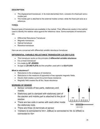
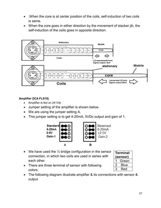
Output current versus position of transducer (mm) & Jib position (%):
Position
[mm]
Jib Position
[%]
Output
[mA]
0 0 20.1
20 10 18.39
40 20 16.79
60 30 15.18
80 40 13.58
100 50 11.99
120 60 10.37
140 70 8.77
160 80 7.20
180 90 5.59
200 100 4.00](https://image.slidesharecdn.com/final2-160717134429/85/maple-leaf-cement-storage-area-machinery-29-320.jpg)


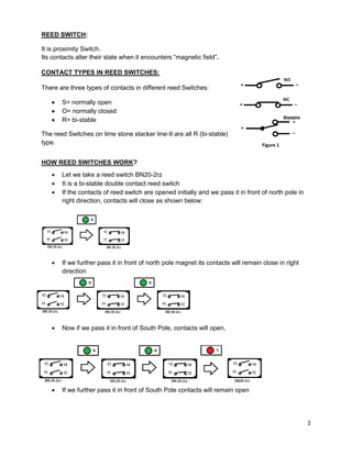
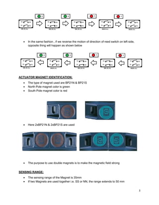
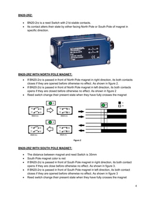
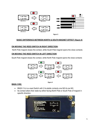
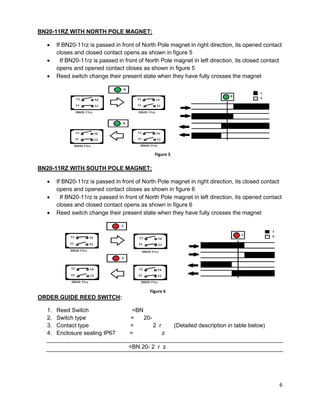
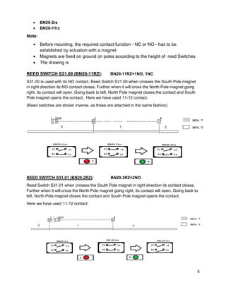
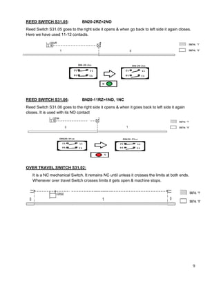
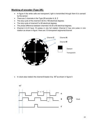
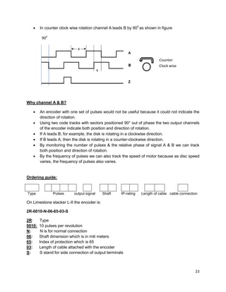
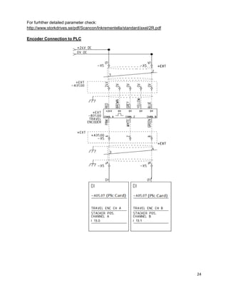
The document discusses magnet reed switches and encoders used on a limestone stacker. It provides details on how reed switches work using magnets and how they are used to sense position. It also discusses the incremental encoder used, which is a 2R encoder that outputs pulses on channels A, B, and Z to detect motion and position.


![Getting Started with Apache Spark: Big Data Made Simple [Free Meetup]](https://cdn.slidesharecdn.com/ss_thumbnails/apachesparkgettingstarted-260203175547-8361bcc3-thumbnail.jpg?width=640&height=640&fit=bounds)


