Bm2 sm2 (eng)
•
0 likes•121 views

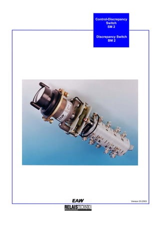
The document describes a control-discrepancy switch that monitors and displays the circuit state of circuit breakers and disconnecting switches. It has two positions staggered by 90 degrees and can be turned 45 degrees further while pressing the switch button. It is used to control circuit breakers and indicate when their position does not match the switch position. The switch consists of nine contacts and a lighting unit to indicate discrepancies. It can operate in preselection circuits by first changing the graphical symbol to preselect a new circuit state before sending the switching command.

Recommended
More Related Content
Similar to Bm2 sm2 (eng)
Similar to Bm2 sm2 (eng) (20)
Recently uploaded
Recently uploaded (20)
Bm2 sm2 (eng)
- 1. Version 03.2003 Control-Discrepancy Switch SM 2 Discrepancy Switch BM 2
- 2. 2 The control-discrepancy switch is used to control circuit-breaker and disconnecting switch and to monitor and display their circuit state in mimic and illuminated mimic diagrams whereas the switch front is designed as graphical symbol. When it lights up it is indicated that the position of the control-discrepancy switch does not match with the assigned circuit breaker. The control- discrepancy switch can be operated in preselection circuits, i.e., the new switch position is preselected by change of the graphical symbol in the mimic diagram, then the switching command for the circuit-breaker is given. The control-discrepancy switch can also be used if control comes first and then the new circuit state is acknowledged. The control-discrepancy switch consists of a packet-type switch with nine wafers, the switching button with lighting unit and a breaker mechanism that has two latched positions staggered by 90°. Furthermore, this position can be turned in the same direction by 45°; however the switching button must be pressed, if not, the switch will jump back into its 90° position. The 90° rotary control switch is used for acknowledgement (signaling switch), and the +45° press-and-twist switch (control switch) is used for control. The lightened switching button is designed in two versions as graphical symbol of the switch: • black bar in white field, display is accomplished by lightening up of the white field • white bar in black field, display is accomplished by lightening up of the white bar Both versions are equipped with a squared black front cover that can be removed, if necessary. The control-discrepancy switch is designed in such a way to match well with the general shape of the switchboard. The signaling switch has two latched positions staggered by 90° and is operated by turning the switching button. For control purposes, the switch may be turned from these positions into the same direction by 45°, while the switching button must be pressed. When the switch is released, it jumps back into its 90° position. Method of operation in the circuit "Preselection Control" Figures 1 to 3 of the Rs 801 280 circuit diagram (internal circuit diagram of Rs 801 362) show the control-discrepancy switch in the preselection circuitry. In figure 1, the control-discrepancy switch is in correspondence with the circuit-breaker. If the circuit state of the circuit-breaker is to be changed, preselection is accomplished by turning the control-discrepancy switch by 90°. After it is turned, the lamp lights up, thus indicating that the position of the control-discrepancy switch does not longer correspond with the circuit-breaker, see figure 2. The circuit-breaker is operated by pressing and turning the switching button by 45°, thus matching again with the switch position, the lamp is out, see figure 3. If the circuit-breaker changes its position, for example by release of a protective relay, the lamp lights up again. This message is acknowledged by turning the switching button of the control-discrepancy switch by 90° to the other side (the lamp is out). Rs 801 280 diagram of connection: Figure 1 Use Design Method of Operation Control-Discrepancy Switch SM 2 2513 17 211197321 4 6 8 10 12 1416 18 20 22 24 2628 N PA E L 2 2/ 1 4 3 (A (E E A
- 3. 3 Rs 801 280 diagram of connection: Figure 2 Rs 801 280 diagram of connection: Figure 3 Method of operation in the circuit "Control Acknowledgement" Figures 4 to 6 of the Rs 801 281 circuit diagram (internal circuit diagram of Rs 801 362) show the control-discrepancy switch connected in such a way to be controlled first and then be acknowledged. Three different circuit states for the control- discrepancy switch and the assigned circuit-breaker are shown. If the circuit state should be changed, see figure 1, the control contacts are closed and thus, the closing solenoid of the circuit-breaker is operated by pressing the switching button of the control-discrepancy switch by 45° in excess of the 90°-position. After it is switched on, the lamp lights up thus indicating that the position of the control discrepancy switch does not longer correspond with the circuit-breaker, see figure 5. Correspondence of the switch position is reached again by turning the control-discrepancy into the "On" position, then the lamp is out, see figure 6. If requested, the signaling lamp can be operated with flashlight instead of permanent light through a clock generator which could be the same for several control-discrepancy switches in the unit. Rs 801 281 diagram of connection: Figure 4 25 25 13 13 17 17 21 21 11 11 9 9 7 7 3 3 2 2 1 1 4 4 6 6 8 8 10 10 12 12 14 14 16 16 18 18 20 20 22 22 24 24 26 26 28 28 (E(A N N P P A A E E L L 2 2 2/ 2/ 1 1 4 4 3 3 (A (E E A E A 2513 17 211197321 4 6 8 10 12 1416 18 20 22 24 2628 N PA E L 2 2/ 1 4 3 (A (E EA
- 4. 4 Rs 801 281 diagram of connection: Figure 5 Rs 801 281 diagram of connection: Figure 6 The discrepancy switch is used as pilot switch to control switches and to monitor and display their circuit state in mimic and illuminated mimic diagrams of electrical installations as well as to indicate the position of valves in pipe systems. The switching button shows the position of the assigned switch and/or valve. When the rotary control switch button lights up it is indicated that the circuit state of the assigned switch and/or valve does not match with the position of the discrepancy switch. Therefore, the discrepancy switch is particularly suitable to be installed into units where the state of the switch should be monitored independently of the control point. The discrepancy switch consists of a packet-type switch with nine changeover contacts, the switching button with lighting unit and a breaker mechanism that has two latched positions staggered by 90°. The lightened switching button is designed in two versions as graphical symbol of the switch: • black bar in white field, display is accomplished by lightening up of the white field • white bar in black field, display is accomplished by lightening up of the white bar Both versions are equipped with a squared black front cover that can be removed, if necessary. The discrepancy switch is designed in such a way to match well with the general shape of the switchboard. 25 25 13 13 17 17 21 21 11 11 9 9 7 7 3 3 2 2 1 1 4 4 6 6 8 8 10 10 12 12 14 14 16 16 18 18 20 20 22 22 24 24 26 26 28 28 (E(A N N P P A A E E L L 2 2 2/ 2/ 1 1 4 4 3 3 (A (E EA EA Use Design BM 2 Discrepancy Switch
- 5. 5 The signaling switch has two latched positions staggered by 90° and is operated by turning the switching button. • Mode of operation as discrepancy switch Figures 1 to 3 of the Rs 801 346 diagram of connection show an example for an application of a BM 2 discrepancy switch to monitor a circuit-breaker L in figure 1, switching state "OFF", and in figure 2, switching state "On" the position of the circuit- breaker L corresponds to that of the discrepancy switch M. In both cases the lamp m is not energized and the graphical symbol of the switch does not light up. If the position of the circuit-breaker L changes, for example if the switch is released by a protective relay, or by executing a switching command from another point, the circuit of the signaling lamp is closed, see figure 3. The graphical symbol of the switch lights up and indicates a new switching state. This message is acknowledged by changing the discrepancy switch, whereby the lamp goes out. Rs 801 346 diagram of connection: Figure 1 – Switch L switched off, position acknowledged Rs 801 346 diagram of connection: Figure 2 – Switch L switched on, position acknowledged Rs 801 346 diagram of connection. Figure 3 – Switch L switched off, position not acknowledged Mode of Operation 117321 4 6 8 12 1410 N P m L A E M 117321 4 6 8 12 1410 N P m L A E M 117321 4 6 8 12 1410 N P m L A E M
- 6. 6 • Mode of operation as a pilot switch In the circuit diagram Rs 801 347, the discrepancy switch is used as pilot switch. If, at the control, a switching operation is performed, the distribution station either receives the "On" or "Off" signal of the assigned switch and, then, gives the switching command. Simultaneously, the graphical symbol of the discrepancy switch is illuminated in the control. If the command is given, instruction sign and graphical symbol of the switch go out. The control necessarily and immediately gets informed on the execution of the switching command. Rs 801 347 diagram of connection: Figure 4 • Mode of operation as alarm indicator According to the Rs 801 348 diagram, the BM 2 discrepancy switch can be used to indicate fault alarms for an optical or acoustic indication. If the protective relay shown in the initial state R switches over into the operated condition, the signal lamp m of the discrepancy switch M lights up and the acoustic signal goes on. When the discrepancy switch M changes into the warning position (bar in the switch front is horizontally), the signal lamp m goes out and the signal device H is switched off. The warning position of the discrepancy switch indicates that there is still a fault in the unit. If the protective relay goes back into its initial position, then lighting up of the signal lamp requires to set back the discrepancy switch. Rs 801 348 diagram of connection: Figure 5 In their mode of operation the switches are working independently of their position. They are suitable to be installed into switchboards of 1 to 15 mm thickness. After removing the switching button and screwing off the front ring, the switch is pushed from the backside through a ∅ 42 mm opening of the switchboard. Then, the front ring is screwed on again with or without the squared black front cover and the switching button is plugged on. After that, the switch has to be turned into the position according to the diagram and then be tightened from the backside by the two fastening screws. In the built-in state, the switches - from the operating side – are provided with IP 40 degree of protection, from the terminal end (behind the switchboard) IP 00 degree of protection. According to the relevant instructions concerning the protection against electric shock the switches have to be installed safe to touch by the installer or, respectively, the operator observing the necessary measures. When exchanging the lamp, the operating handle should only be removed in the de-energized state of the lamp circuit. Installation of the SM 2Control-Discrepancy Switch and the BM 2 Discrepancy Switch 117321 4 6 8 12 1410 N P m L A E M 117321 4 6 8 12 1410 N P m R A E M H
- 7. 7 The switch is connected to the screw terminals on its backside (switch and lighting), i.e., behind the switchboard according to circuit diagram or, respectively, the selected circuit. To connect the wiring, screw-type terminals used for wire range from von 1 × 0,75 mm² up to 1 × 4 mm² Cu, single- and multicore, and/or 1 × 1 mm² up to 1 × 2,5 mm² Cu, finely stranded, are provided. Any dead metal parts of the switches are connected to the ground terminal point. This point has to be incorporated by the user into the protective measures of the electro technical unit. Depending on the specific circuit of the switch contacts, the user shall provide appropriate measures to meet the requirements of the law of electromagnetic compatibility. The products are manufactured in line with a quality management system according to the requirements of the DIN EN ISO 9004 standard as well as they are documented in line with DIN EN ISO 9001. The following national and international standards shall apply to the low-voltage switchgears: DIN EN 60947-1 / VDE 0660 Part 100: 2002-12 Low-voltage switchgears Part 1: General Provisions DIN EN 60947-3 / VDE 0660 Part 107: 2001-12 Low-voltage switchgears Part 3: Load switches, disconnectors, load-interrupter switches and fuse combination units DIN EN 60947-5 / VDE 0660 Part 200: 2000-08 Low-voltage switchgears Part 5 – 1: Control units and switching elements – electromechanical control units DIN VDE 0110-1 / VDE 0110 Part 1: 1997-04 Insulation coordination for electrical equipment in low voltage units Part 1: Principles, requirements to tests DIN EN 60529 / VDE 0470 Part 1: 2000-09 Degrees of protection provided by enclosure (IP code) DIN EN 60999-1 / VDE 0609 Part 1: 2000-12 Connecting devices – electrical copper conductors – safety requirements for screw-type terminals Part 1: General requirements and specific requirements for terminal point for conductors from 0.2 mm² up to including 35 mm² Lighting of the Rotary-Control Switch Button Rated voltage 24 V up to 230 V DC/AC, see list of order numbers Limits of rated voltage 85 % up to 110 % Rated consumption: 24 V AC/DC 32 V AC/DC 42 V AC/DC 48 V AC/DC 60 V AC/DC 80 V AC/DC 100 V AC/DC 110 V AC/DC 125 V DC; 127 V AC 220 V DC; 230 V AC ⇒ 3,0 W / VA ⇒ 4.0 W / VA ⇒ 5.0 W / VA ⇒ 5.5 W / VA ⇒ 7.0 W / VA ⇒ 9.5 W / VA ⇒ 12.0 W / VA ⇒ 12.5 W / VA ⇒ 14.0 W / 14.5 VA ⇒ 24.5 W / 26.5 VA Lamp Ba9s 24 V / 3 W Connection of the SM 2 Control-Discrepancy Switch and the BM 2 Discrepancy Switch Manufacturing quality of the SM 2 Control-Discrepancy Switch and the BM 2 Discrepancy Switch Technical Parameter of SM Control-Discrepancy Switch and of BM 2 Discrepancy Switch Survey of Standards of SM 2 Control-Discrepancy Switch and BM 2 Discrepancy Switch
- 8. 8 Switch Parameters Maximum switching voltage: 400 V AC, 50 / 60 Hz 250 V DC Maximum making current 9 A Conventional thermal current 6 A Utilization category AC 21 • Rated operating voltage • Rated operating current switching of resistive loads including slight overload 230 / 400 V AC 6 A AC Utilization category AC 15 • Rated operating voltage • Rated operating current control of electromagnetic load 230 / 400 V AC 1 A AC Utilization category DC 13 • Rated operating voltage • Rated operating current control of electromagnetic loads 220 V DC 0.5 A DC Switching rate ≤ 30 s.r per h or, resp., according to utilization category Voltage endurance according to utilization category Mechanical endurance ≥ 2 × 10 5 switching cycles Ambient temperature -10°C up to 45°C Function indicator • rotary control switch button depending on design type environment lighted or central bar lighted Operating position any Number of contacts ⇒ SM 2 control-discrepancy switch • switch • pushbutton ⇒ BM 2 discrepancy switch • switch 4 changeover contacts depending on design type, see circuit diagrams 3 changeover contacts Rated insulation voltage • Lighting • SM 2, BM 2 switches according to DIN VDE 0110-1 / VDE 0110 Part 1: 04.97 250-volt 400-volt degree of pollution 3 according to DIN EN 60947-1 / VDE 0660 Part 100: 2002-12 Rated power-frequency voltage strength • Lighting • SM 2, BM 2 switches 2.0 kV 2.5 kV Rated surge withstand strength • lighting • SM 2, BM 2 switches according to DIN EN 60947-1 / VDE 0660 Part 100: 2002-12 - 4.0 kV, voltage form 1.2/50 µs Clearances in air • lighting • SM 2, BM 2 switches according to DIN EN 60947-1 / VDE 0660 Part 100: 2002-12 ≥ 3 mm ≥ 4 mm Creep age distances • lighting • SM 2, BM 2 switches according to DIN EN 60947-1 / VDE 0660 Part 100: 2002-12 ≥ 4.0 mm ≥ 6.3 mm Electric shock protection safe from touch by the back of the hand and the fingers in the installed state from the operating side Degree of protection • operating side • connecting side according to DIN EN 60529 / VDE 0470 Part 1: 2000-09 IP 40 IP 00 Connections • type attachment • wire range according to DIN EN 60999-1 / VDE 0609 Part 1: 2000-12 screw-type terminals 1 × 0,75 mm² up to 1 × 4 mm² singe- and multicore 1 × 1.0 mm² up to 1 × 2.5 mm² finely stranded Dimensions, see also dimensioned drawings • depth of SM 2 control-discrepancy switch • depth of BM 2 discrepancy switch • switch button • front cover, black • fixing opening of the switchboard • permissible thickness of switchboard ≤ 184 mm ≤ 157 mm ∅ 52 mm 52 mm × 52 mm × 1 mm ∅ 42 mm 1 mm ... 15 mm Dimensioned drawings • SM 2 control-discrepancy switch • BM 2 discrepancy switch Rs 805,575 Rs 805,149 Weight • SM 2 control-discrepancy switch • BM 2 discrepancy switch about 0.6 kg about 0.6 kg
- 9. 9 Circuit diagrams: ⇒ SM 2 control-discrepancy switch • circuit diagrams: • circuit “preselection → control" • circuit “control → acknowledgement” ⇒ BM 2 discrepancy switch • circuit diagram • discrepancy switch with switch position • discrepancy switch as pilot switch • discrepancy switch as alarm indicator Rs 801 362, Rs 801 473, Rs 801 449 Rs 801 280 Rs 801 281 Rs 801 303 Rs 801 346 Rs 801 347 Rs 801 348 Operating instructions Rs 808 067 SM 2 control-discrepancy switch Circuit diagram Rs 801 362: Circuit diagram Rs 801 473 (special design) Circuit diagram Rs 801 449 (special design) BM 2 discrepancy switch Circuit diagram Rs 801 303: Internal Circuit Diagrams of SM 2 Control-Discrepancy Switch and BM 2 Discrepancy Switch 2513 17 211197321 4 6 8 10 12 14 16 18 20 22 24 26 28 2/ 1 2 4 3 7 11321 4 6 8 10 12 14 A E 2513 17 211197321 4 6 8 10 12 14 16 18 20 22 24 26 28 5 2/ 1 2 4 3 2513 17 211197321 4 6 8 10 12 14 16 18 20 22 24 26 28 5 2/ 1 2 4 3
- 10. 10 SM 2 control-discrepancy switch Dimensioned drawing Rs 805 575 BM 2 discrepancy switch Dimensioned drawing Rs 805 149 Dimensions of SM 2 Control-Discrepancy Switch and BM 2 Discrepancy Switch
- 11. 11 SM 2 control-discrepancy switch Rated voltage Pl. nos. of lighting of switch button [ UN ] Environment lighted Arrangement acc. to circuit diagram Rs 801 362 Central bar lighted Arrangement acc. to circuit diagram Rs 801 362 Environment lighted Arrangement acc. to circuit diagram Rs 801 473 1) Environment lighted Arrangement acc. to circuit diagram Rs 801 449 1) 24 V 1 732 527 002 1 732 537 002 1 732 527 702 1 732 527 802 32 V 1 732 527 003 1 732 537 003 1 732 527 703 1 732 527 803 42 V 1 732 527 004 1 732 537 004 1 732 527 704 1 732 527 804 48 V 1 732 527 005 1 732 537 005 1 732 527 705 1 732 527 805 60 V 1 732 527 006 1 732 537 006 1 732 527 706 1 732 527 806 80 V 1 732 527 007 1 732 537 007 1 732 527 707 1 732 527 807 100 V 1 732 527 008 1 732 537 008 1 732 527 708 1 732 527 808 110 V 1 732 524 000 1 732 534 000 1 732 524 700 1 732 524 800 125 V / 127 V 1 732 527 009 1 732 527 009 1 732 527 709 1 732 527 809 220 V / 230 V 1 732 526 000 1 732 536 000 1 732 526 700 1 732 526 800 f. a. rated voltages 1 732 527 00 . 1 732 537 00 . 1 732 527 70 . 1 732 527 80 . 1) special design BM 2 discrepancy switch Rated voltage Pl. nos. of the lighting of switch button Environment lighted Central bar lighted 24 V 1 732 023 002 1 732 027 002 32 V 1 732 023 003 1 732 027 003 42 V 1 732 023 004 1 732 027 004 48 V 1 732 023 005 1 732 027 005 60 V 1 732 023 006 1 732 027 006 80 V 1 732 023 007 1 732 027 007 100 V 1 732 023 008 1 732 027 008 110 V 1 732 021 000 1 732 025 000 125 V / 127 V 1 732 023 009 1 732 023 009 220 V / 230 V 1 732 022 000 1 732 026 000 f. a. rated voltages 1 732 023 0 . . 1 732 027 0 . . Spare part order number switch button Rs 6 821 249 90 collar white Rs 6 821 147 00 collar black Rs 6 821 148 00 lamp Ba9s 24 V / 3 W; DIN 49 715 / IEC 7004 - 14 List of Order Numbers of SM 2 Control-Discrepancy Switch and BM 2 Discrepancy Switch Spare Parts of SM 2 Control-Discrepancy Switch and BM 2 Discrepancy Switch
- 12. 12 Die Experten der EAW Relaistechnik GmbH nehmen sich gern Zeit für ein informatives Gespräch mit Ihnen. Natürlich kostenlos und unverbindlich. So haben Sie Gewissheit, dass wir die richtigen Partner sind. The specialists of EAW Relaistechnik GmbH will be glad to take time out to meet you for informative talks. Convince yourself – without charge – that you have found the right partner in us. EAW RELAISTECHNIK GMBH Hauptstraße 13 10317 Berlin, Germany www.eaw-relaistechnik .de Phone +49-30-55 76 22 00 Fax +49-30-55 76 22 03 e-mail vertrieb@eaw-relaistechnik.de Schließen Sie Kontakt mit uns! Make contact with us!