This document provides an introduction to the book "Manufacturing Processes for Design Professionals" which explores established, emerging and cutting-edge production techniques that are important for design practice. The book aims to restore the balance between design and manufacturing. It is organized into sections on processes and materials to provide relevant information to aid design decision making. Developments in key processes like injection molding and rapid prototyping are discussed, showing how they continue to push boundaries and influence new design approaches. Case studies showcase real manufacturing examples.
![/•
Part Two
Cutting Technology
Chemical
Photochemical Machining
Thermal
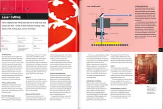
Laser Cutting
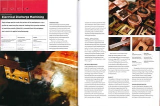
Electrical Discharge Machining
Die Sink EDM
Wire EDM
Part Three
Joining Technology
Thermal
Arc Welding
Manual Metal Arc Welding (MMA)
Metal Inert Gas Welding IMIG)
Tungsten Inert Gas Welding (TIG)
Plasma Welding
Submerged Arc Welding (SAW)
Power Beam Welding
Laser Beam Welding [LBW]
Electron Beam Welding (EBW)
Friction Welding
Rotary Friction Welding (RFW)
Linear Friction Welding (LFW)
Orbital Friction Welding (OFW)
Friction Stir Welding (FSWl
Vibration Welding
Ultrasonic Welding
Resistance Welding
Projection Welding
Spot Welding
Seam Welding
Mechanical
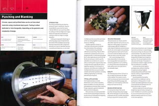
2UU Punching and Blanking 260
Die Cutting 266
248 Water Jet Cutting 272
254 Glass Scoring 276
Soldering and Brazing 312
282 Conduction Method
Torch Method
Furnace Method
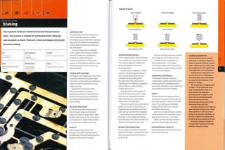
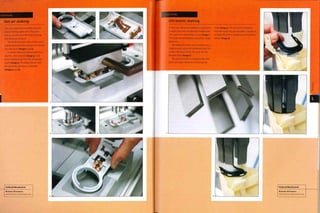
Staking 316
Hot Air Staking
Ultrasonic Staking
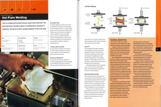
288 Hot Plate Welding 320
Mechanical
294 Joinery 324
Weaving 332
Upholstery 338
Timber Frame Structures 344
298
302
308
Part Four
Finishing Technology
Additive Processes
Spray Painting 350
Powder Coating 356
Electrostatic Spraying
Fluidized Bed Powder Coating
Anodizing 360
Electroplating 364
Galvanizing 368
Vacuum Metalizing 372
Subtractive Processes
Grinding, Sanding and Polishing 376
Wheel Cutting
Belt Sanding
Honing
Lapping
Electropolishing 384
Abrasive Blasting 388
Photo Etching 392
CNC Engraving 396
Printing
Screen Printing 400
Pad Printing 404
Hydro Transfer Printing 408
Foil Blocking and Embossing 412
Part Five
Materials
Introduction to Materials 418
Plastics
Introduction to Plastics 424
Thermoplastic 430
Thermoset 440
Bioplastic 446
Metals
Introduction to Metals 448
Ferrous 454
Non-Ferrous 457
Wood and natural fibres
introduction to Wood 464
Softwoods 470
Hardwoods 472
Natural fibres 480
Ceramics and Glass
Introduction to Ceramics and Glass 482
Ceramics 488
Glass 490
Directory
Glossary and Abbreviations 496
Featured Companies 502
Organizations and Other Sources 512
of Information
Further Reading 516
Illustration Credits 519
Acknowledgments 522
Index 524](https://image.slidesharecdn.com/manufacturingprocessesfordesignprofessionals-231008134532-9d8b1244/85/Manufacturing-Processes-for-Design-Professionals-pdf-5-320.jpg)
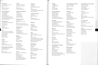
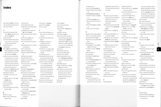
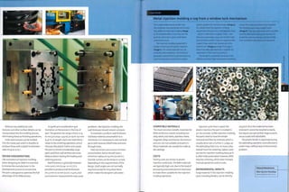
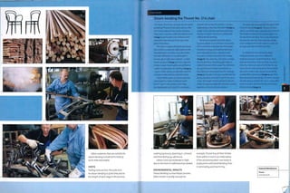
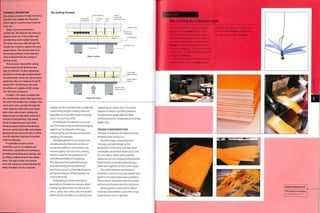
![TECHNICAL DESCRIPTION
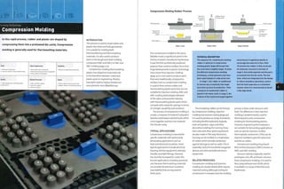
Vacuum forming is a straightforward
process and provides the foundation for the
other thermoforming techniques. A sheet of
material is heated to its softening point. This
is different for each material. For example,
the softening point of polystyrene (PS) is
127-182°C (261-360°F| and PP is U3-165°C
(289-329°F). Certain materials, such as
HIPS, have a larger operating window (that
is, the temperature range in which they are
formable), which makes them much easier
to thermoform.
The softened plastic sheet is blown into
a bubble, which stretches it in a uniform
manner. The airflow is then reversed and
the tool is pushed up into the sheet. The
material is drawn onto the surface of the
mold by vacuum at about 0.96 bar (14 psi).
To assist the flow of air, channels are drilled
into the tool. They are located in recesses
and across the surface of the mold to extract
the air as efficiently as possible.
Pressure forming is the reverse of
vacuum forming; the sheet is formed onto
the surface of the mold under approximately
6.9 bar (100 psi) of air pressure. This
means that a greater level of detail can be
achieved. Surface details on the mold will
be reproduced with much more accuracy
than vacuum forming. Surface finish can be
more accurately controlled and is therefore
functional. However, like vacuum forming
only one side of the sheet will be functional.
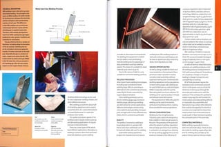
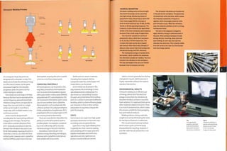
Thermoforming Processes
Preheated sheet
Plug-assisted forming is used to bring
the benefits of male mold forming to female
parts because blowing a softened sheet into
a bubble stretches it evenly while draping
the sheet into a female mold produces more
localized stretching. The plug stretches
the sheet prior to forming and so ensures
that there is adequate wall thickness for
deep profiles. Otherwise the material
will tear. When the air Is drawn out, the
sheet conforms to the mold profile and the
hydraulic plug retracts.
In twin sheet thermoforming, 2 sheets
are thermoformed and clamped together.
Forming the vacuum
This forms an enclosed and thin walled
product. Both sides of the product are
functional, unlike the single sheet processes.
The machines are rotary. The clamps
transfer the sheet into the heating chamber,
where it is raised to softening temperature;
it Is then thermoformed and clamped; and
finally rotated to the unloading station. The
2 sheets are thermoformed individually, one
above the other. Once fully formed they are
clamped together. Residual heat from the
thermoforming enables the bond to form
with prolonged contact. The bond has similar
strength to the parent material.
Multilayered materials are
coextruded to provide benefits: for
example, providing a barrier to moisture
or bacteria; different colours; and
sandwiching recycled material between
films of virgin (aesthetic) material to
reduce energy.
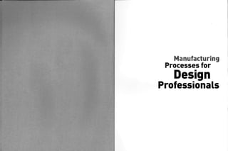
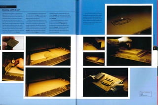
Textured sheets can be thermoformed
(see image, page 31, above left).Typically
sheets are textured on one side and
so the smooth side is formed against
the m old. There is a range of standard
textures, which are cast or extruded by
the material manufacturer. Examples
include frosted, haircell, lens, embossed
and relief.
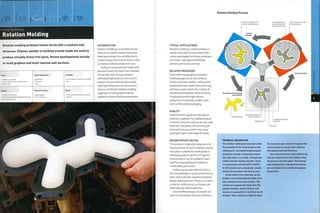
Twin sheet thermoforming
produces 3D hollow parts.This has
added benefits including lightness
and rigidity, insulation and 2 separate
m ateri al s (upper an d 1 ower). Sin gl e
sheet thermoforming is typically limited
to only a single side of functionality.
Twin sheet, on the other hand, provides
functional surfaces on both sides.
Foam can be molded into twin sheet,
or be injected post-forming for added
rigidity and strength (see image, page
31, above, right).
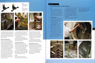
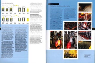
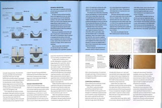
DESIGN CONSIDERATIONS
Thermoforming is ideal for shallow thin
walled parts. It is not usually practical
forthe depth to exceed the diameter.
Materials can be stretched more evenly
over the surface of a deep profile using
plug-assisted forming.
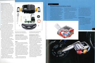
Air channels on the surface of the
mold will leave slight pimples.These
can be eliminated on aesthetic surfaces
with the use of microporous aluminium
molds (see image, top).This material
has a much shorter molding lifespan
because the pores clog up eventually.
However, they are very useful for design
details (see image, middle), which would
otherwise require hundreds of air
channels (holes).
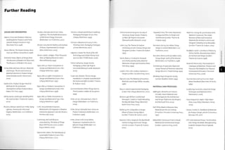
Plug-assisted forming
Heated and
softened sheet
Clamp ring
Female mold
Air channels
1—
v y ¦ 1
1—— It!
Upper mold
Plug-assisted preheated sheet Forming the vacuum
Twin sheet thermoforming
Air sucked out
from both sides
1
/
fiH]
Lower mold
Preheated sheets
Textures are sometimes necessary
on the surface of the mold to assist the
flow of air and avoid air pockets forming.
These are known as 'open textures'.
Sheet fed thermoforming is used to
process sheet materials ranging from
i mm to 12 mm (0.04-0.47 in.). Roll fed
is supplied by a reel and so is limited to
o.i mm to 2.5 mm (0.004-0.1 in.).The size
of part is typically restricted to 1.5 x 3.5 m
(5 x 11.5 ft), although some machines are
capable of dealing with sheets of 2.5 X4m
(8 x13 ft).
Draft angles are essential when
th erm oformi n g over protrusi on s, or m al e
molds. This is because the heated plastic
sheet is expanded; as it cools it will shrink
by up to 2%. Different materials have
different levels of shrinkage: for example,
ABS will shrink 0,6% and H DPE 2%. A draft
angle of 2° is usually recommended.
The material stretches as it Is
thermoformed, and this will be more
prominent in deeper and undulating
profiles.Therefore, care must be taken
to avoid sharp corners and points where
three corners meet.These will cause
excessive thinning and thus weak points.
Forming the vacuum and clamping
COMPATIBLE MATERIALS
Although almost all thermoplastic
materials can be thermoformed, the
most common are ABS, polyethylene
terephthalate (PET) (including PETG,
which is PET modified with glycol),
polypropylene (PP), polycarbonate (PC),
high impact polystyrene (HIPS) andhigh
density polyethylene (H DPE).The glycol in
PETG reduces brittleness and premature
ageing. PETG is clear (almost like PC)
and is therefore often the material of
choice for lighting diffusers and medical
packaging, for example.
COSTS
Tooling costs are typically low to
moderate, depending on the size,
complexity and quantity of parts. The
most expensive tools are machined
aluminium.Tooling for pressure forming
is 30-50% more expensive than vacuum
forming, but is still considerably cheaper
than tooling for injection molding.
The speed of thermoforming depends
on the selected process and material
thickness. Sheet fed processes typically
produce 1-8 parts per minute. Roll
fed machines are generally faster and
multiple cavity tools can make hundreds
Top Above
Microporous aluminium Carpet covered
moldmaking material, thermoforming
shaped by CNC machining, produced in a single
operation.
Middle
Textured design feature
vacuum formed on mold
made of microporous
aluminium.
of parts per minute. Roll fed machines
are automated, while sheet fed machines
are generally loaded by hand. This
increases labour costs.
ENVIRONMENTAL IMPACTS
This process Is only used to form
thermoplastic materials, so the majority
of scrap can be recycled. Kaysersberg
Pi asti cs, wh o provi ded th e extrudl n g
the sheet material case study (page 34),
produce only 1.4% scrap material; the rest
is recycled.
Sheet conforms
to mold profile
Mold
pushes up
into sheet](https://image.slidesharecdn.com/manufacturingprocessesfordesignprofessionals-231008134532-9d8b1244/85/Manufacturing-Processes-for-Design-Professionals-pdf-18-320.jpg)
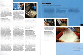
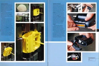
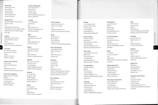
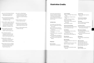
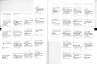
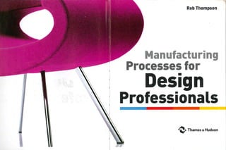
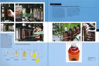
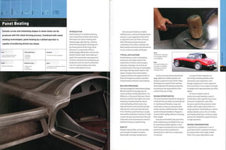
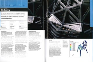
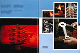
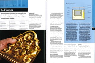
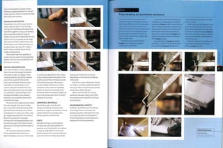
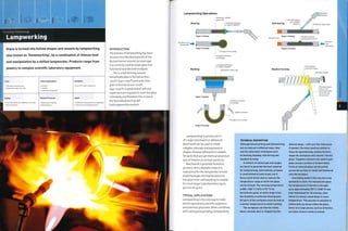
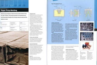
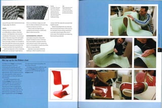
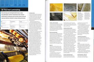
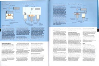
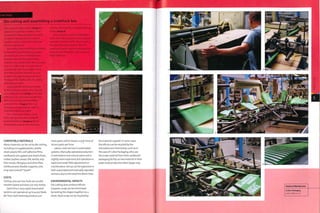
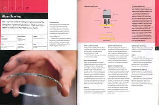
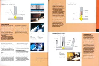
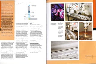
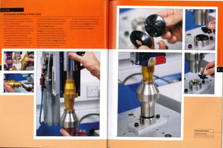
![ase Study
Moldflow analysis
Prior to manufacturing, Moldflow software is
used to analyse and maximize the efficiency
of a design. The software is suitable for
all types of plastic injection molding and
metal die casting. It brings together part
design, material selection, mold design and
processing conditions to determine the
manufacturability of the part. This reduces
the costs and time delays associated with
otherwise unforeseen manufacturing
problems. It also maximizes the efficiency
of production and can reduce material
consumption with significant savings.
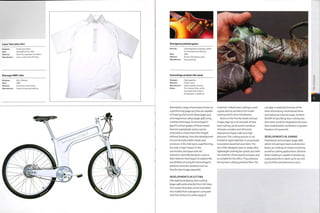
A 3D model of the required part is
generated in a suitable computer aided
design (CAD) or computer aided engineering
(CAE) software package.
Moldflow is a predictive analysis tool
used to simulate the 3D model in production
to analyse filling, packing and cooling.
The examples below illustrate analysis of flow,
warp, fibre orientation, cooling and stress,
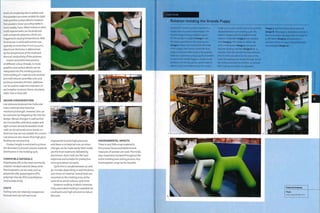
MPI/FLOW
MPI/Flow simulates the filling and packing
phases in the molding process, helping to
predict the behaviour of the material as it
flows through the die cavity. This is used to
optimize the location of the gate, balance
runner systems and predict potential
problems. Different versions are used
to simulate different plastic and metal
molding techniques.
The MPI/Flow is here demonstrated on
3 products. Two stages of an Abtec part are
simulated (images 1 and 2) to demonstrate
confidence of fill, which is colour coded, MPI/
Flow was used to simulate various
gate positions and runner system
configurations.
By changing the location of the gate on
the automotive hubcap for PolyOne (image 3)
it was possible to reduce stress and make sure
there were no air traps in critical areas.The
colour scale indicates bulk stress.
The colour scale on the automotive
Interior product manufactured by Resinex
and Gaertner & Lang (image 4) indicates
fill time in seconds. Appearance is very
Important, so the flow analysis software
was used to eliminate weld lines and colour
variation in critical areas. This was achieved
by changing the location of the gate and
temperature of the runner system.
Confidence Of Fill
Low 1
Confidence Of Fill
Low
High
[sec]
Featured Manufacturer
Moldflow
www. m 0 Id flow, com
MPI/WARP
This analysis too] is used to predict
shrinkage and warping, which are the
result of stresses built up during the
molding process. The Information is
used to specify material selection and
processing parameters to minimize
potential problems.
Any more than 5 mm (0.2 in.) warp
was unacceptable on this Efen electronic
switchboard cabin (image 5). The analysis
found that by reducing wall thickness
warp could be reduced by go%.
On the CAD model for a Jokon
automotive lamp assembly (image 6), it
was essential that the part did not warp
so that it would maintain a water-tight
seal in application. Warpage was reduced
by 50% by optimizing wall thickness
(images 7 and 8).
MPI/COOL
MPI/Cool 1s used to analyse the design
of mold cooling circuits. Uniform cooling
is important to make sure that the
part does not warp and to minimize
cycle times.
A filter housing manufactured by
Hozelock shows the configuration of
the mold cooling circuits (images 9
to 11). Changing the layout of the circuit
reduced cycle time by 2 seconds and so
saved more than 4% of the production
cost; reducing the wall thickness reduced
cycle time by 7.3 seconds and shot weight
by 19,6%, saving 24% of the production
costs. Combining the 2 produced 26.1%
overall savings.](https://image.slidesharecdn.com/manufacturingprocessesfordesignprofessionals-231008134532-9d8b1244/85/Manufacturing-Processes-for-Design-Professionals-pdf-30-320.jpg)
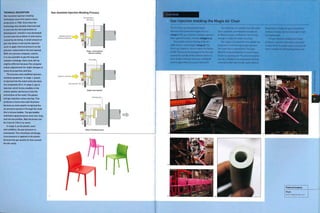
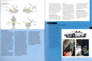
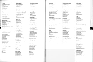
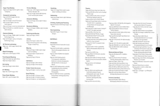
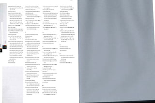
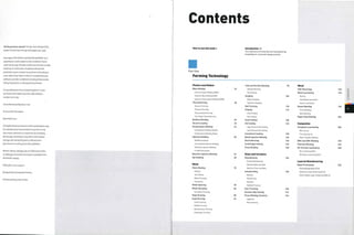
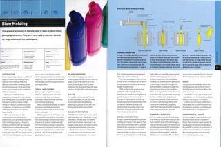
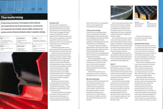
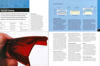
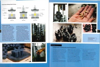
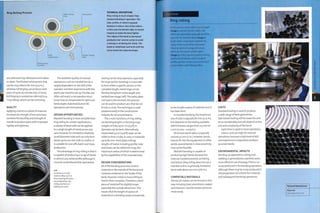
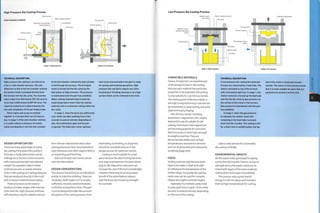
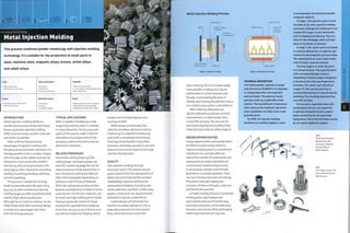
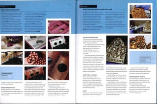
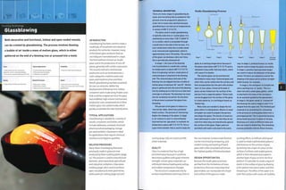
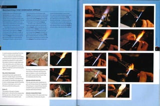
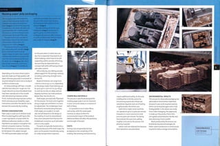
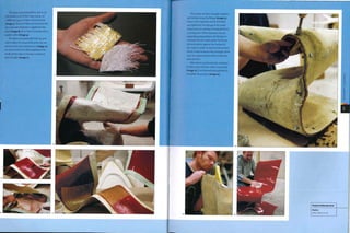
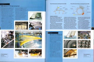
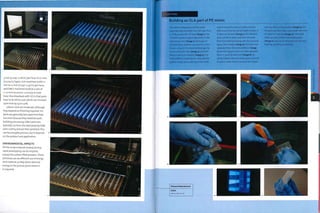
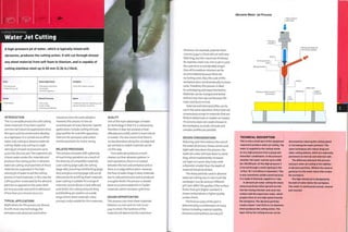
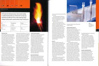
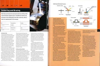
![Superforming Process
Cavity forming
Stage 1; Preheated sheet loaded stage 2; Pressure applied
Bubble forming
LUl
EH]
Stage 1; Preheated sheet loaded
and blown
Backpressure forming
Stage 2: Vacuum applied
D 1}
Stage 1: Preheated sheet loaded Stage 2: Pressure applied
Diaphragm forming
1} ft D
Stage 1: Preheated sheet loaded Stage 2: Pressure applied
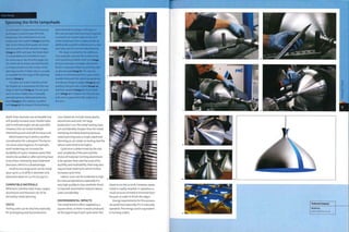
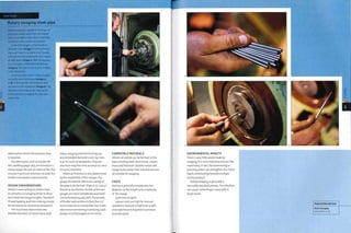
TECHNICAL DESCRIPTION
In all U superforming processes a sheet of
metal is loaded into the machine, clamped
in place and heated to between 450°C and
500°C (840-932oF). The temperature is
determined by the type and thickness of
sheet material.
In cavity forming, the hot metal sheet is
forced onto the inside surface of the tool by
air pressure at 1-30 bar (U.5-435 psi|. The
hot metal is superplastic and so forms easily
over complex and intricate shapes. This
process is generally used to manufacture
large shallow parts.
Bubble forming is similar to
thermoforming. In stage 1, the hot metal
sheet is blown into a bubble and the tool
rises into the mold chamber. In stage 2, the
pressure is then reversed and the bubble of
metal is forced onto the outside surface of
the tool. This process is ideal for deep and
complex parts. The wall thickness is uniform
because the bubble process stretches the
material evenly prior to forming.
Backpressure forming is very similar
to cavity forming. The difference is that in
backpressure forming air pressure is also
applied to the reverse side of the hot metal
sheet as it is being superformed. In this way
the forming process is more controlled and
reduces the stress on the hot metal sheet.
Diaphragm forming was developed to
superform so-called 'non-superplastic'
alloys. It can achieve this because the
metallic sheet diaphragm supports the
hot metal sheet and aids the flow of
material into complex 3D profiles, by
sustained tensile stress is less than 25%
of the minimum specified yield strength.
DESIGN CONSIDERATIONS
The maximum size of part that
can be formed is different for each
superforming technique. In each case, 1
of the limiting dimensions can often be
exceeded depending on part geometry
and alloy selection.
Cavity forming can be used to produce
parts up to 3,000 x2,000 x600 mm (n8
x 79 x 24in.) and 10 mm (0.4in.) thick,
while bubble forming can be used to
produce parts up to 950 x 650 x 300 mm
(37 x 26 x 12 in.) and 6 mm (0.236 in.) thick.
Backpressure forming has a maximum
plan area of roughly 4,500 mm2 (6.97
in.2), and diaphragm forming can be used
to produce parts up to 2,800 x 1,600 x
600 mm (110 x 63x24 in.).
Different alloys have different
mechanical and physical properties, and
this must be taken into consideration
during the design process. It may well
be possible to form a complex shape in
i alloy, but that alloy may not have the
properties requiredfor in-service use.
Primary structure applications for the
aerospace industry require high strength
alloys accompanied with good service
properties such as fatigue toughness
and stress corrosion resistance.These
requirements are adequately met
with the alloy 7475, which has been
successfully used to form air intake
lip skins and access door assemblies,
for example. For less demanding
applications the heat-treated version
of 2004 has found many applications
for secondary structures such as
aerodynamicfairings and stiffeners.
allowing unrestrained movement of the
component sheet.
THE BUBBLE FORMING SEQUENCE
The bubble forming sequence shows how
aluminium is superformed. The hot metal
sheet is blown Into a bubble in the molding
chamber (image 1). The tool rises up into
the metal bubble. Only a virtual image of
this stage of the process is shown in image
2 because the metal sheet is not usually
translucent. As the tool rises up the hot
metal is forced onto its surface by air
pressure (image 3). The tool continues to
rise and the metal is forced onto it until the
forming process is complete and the tool
can be retracted (image 4). The part is now
formed and ready for trimming and any
other post-forming operations.
In the formed condition the alloy has
suitable mechanical properties for
internal fittings such as kicking panels
andlight fittings.
COMPATIBLE MATERIALS
Superplastic metals that can be shaped
in this manner include aluminium,
magnesium and titanium alloys.The
most commonly formed aluminium
sheet materials include 5083,2004
and 7475.
COSTS
Although tooling costs can be quite low
compared to matched die tooling, they
do depend on the size and complexity
of the part. Cycle time is rapid, typically
5-20 minutes.
Labour costs are moderate. Each part
is trimmed and cleaned post-forming.
ENVIRONMENTAL IMPACTS
Scrap and offcuts are recycled to produce
new sheets of aluminium and other
aluminium products.](https://image.slidesharecdn.com/manufacturingprocessesfordesignprofessionals-231008134532-9d8b1244/85/Manufacturing-Processes-for-Design-Professionals-pdf-49-320.jpg)
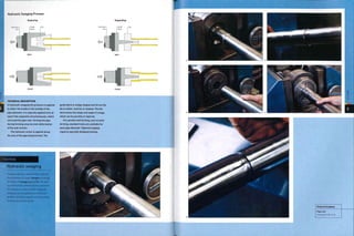
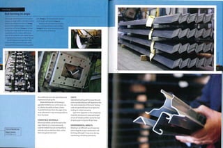
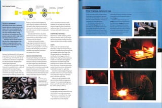
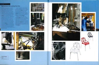
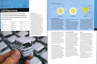
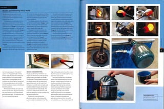
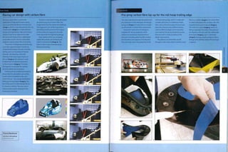
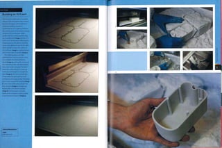
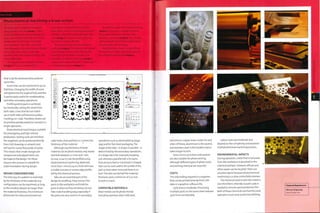
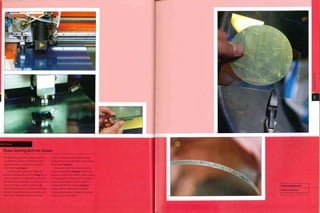
![Forming Technology
Tube and Section Bending
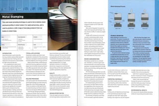
INTRODUCTION
Architects and designers have long
utilized the functional and aesthetic
properties of bent metal, especially
tubular steel. Bending methods are
generally inexpensive and make use
of the ductility and strength of metal.
Bending minimizes cutting andjoining
in certain applications, which reduces
waste and cost.
There are 2 main types of tube and
section bending, which are mandrel
bending and ring rolling (see images,
opposite, above).
Mandrel bending is specifically
designed for making small radii in metal
tube. It is named after the mandrel that
is inserted into the metal tube to prevent
it from collapsing during bending. Ring
rolling is used to form continuous and
generally larger bends in both tube and
section (extruded profile or bar). It is also
commonly known as section bending.
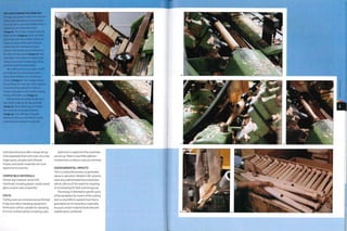
Used mainly in the furniture, automotive and construction
industries, this process is used to form continuous and fluid
metal structures. Tight bends can be formed with a mandrel over
a rotating die, or long and undulating curves between rollers.
Costs
r] • No cost for standard tooling
i • Moderate to high cost for specialized tooling
• Low to moderate unit costs
Typical Applications
• Construction
• Furniture
• Transport and automotive
Suitability
• One-off to high volume production
Related Processes Speed
Quality
• High • Arc welding
• Press braking
• Swaging
• Rapid cycle time
• Machine setup time can be long
Steam bent (page 198) furniture was
the precursor to tubular steel and uses
similar bending techniques.Tubular
steel was developed in Germany for the
automotive and aerospace industries,
andThonet saw its potential. In the 1920s
they began developing tubular steel
furniture with members of the Bauhaus,
including Mart Stam, Marcel Breuer and
Mies van der Rohe. Many of the designs
from this time are still in production.
TYPICAL APPLICATIONS
Metalwork is either bent as a continuous
length, or fabricated using cast or
pre-bent 'elbows' to join straight
sections. Many products are formed by
mandrel bending, including domestic
and office furniture, security fencing
and automotive applications (such as ,
exhaust pipes).
Ring rolling can be used to bend
a range of profiles (tube, extrusions
and bar) into large-radius bends.
Many products are formed using this
technique such as structural beams (for
bridges and buildings), architectural
trims (on curved facades) and street
furniture. In fact, most bent metalwork in
construction will be processed using ring
rolling. Rolling sheet materials is known
as plate rolling.
It is even possible to produce 3D
section bends such as the tracks on a
rollercoaster, which can be achieved with
careful manipulation on aring roller.
RELATED PROCESSES
Tubular metalwork consists of mainly
bending,press braking (page 148) and
arc welding (page 282). Press braking is
capable of producing taperedhollow
profiles with multiple bends on a suitably Above, left
shaped punch. An example of this is
hexagonal lampposts that are tapered
along their length.
Ring rolling can produce similar
profiles to roll forging (page 114). The
difference is that roll forged components
Mandrel Bending Process
The legs of tables and
chairs are commonly
produced by mandrel
bending.
Above
Ring rolling can shape
tube, extruded profile
and metal sheets. The
arc can be adjusted
along its length to give
non-circular bends.
CD
m
>
in
m
o
z
D
Mandrel
Stage 1: Load
TECHNICAL DESCRIPTION
The metal blank Itubel Is loaded over
the mandrel and clamped onto the die.
Non-mandrel forming Is only possible for
certain parts with thicker walls.
The blank Is drawn onto the rotating
die as It spins, and the mandrel stops the
walls collapsing at the point of bending.
The pressure clamp travels with the tube
to maintain an accurate and wrinkle free
bend. An additional clamp Is sometimes
required to prevent wrinkling on the
Stage 2: 90° bend
inside of the bend, especially for very thin
walled sections.
The size of the rotating die determines
the radius of the bend. The distance
travelled determines the angle of bend.](https://image.slidesharecdn.com/manufacturingprocessesfordesignprofessionals-231008134532-9d8b1244/85/Manufacturing-Processes-for-Design-Professionals-pdf-51-320.jpg)
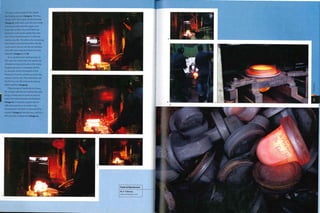
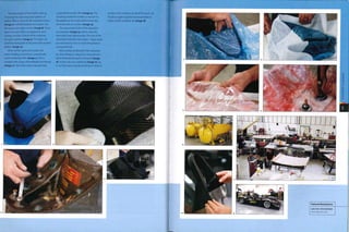
![Forming Technology
Forging
The forming of metal by heating and hammering or pressing was
traditionally performed by blacksmiths on anvils. Nowadays,
forgings are made by hammering, pressing or rolling hot metal
with sophisticated dies and extreme pressure.
1 Moderate to high tooling costs
1 Moderate unit costs
Quality
• Excellent grain structure
Typical Applications
• Automotive and aerospace
• Hand tools and metal implements
• Heavy duty machinery
Related Processes
• Casting
• Machining
• Tube bending (ring rolling]
Suitability
• All types of production
Speed
• Rapid cycle time [typically less than
a minute) depending on size, shape
and metal
INTRODUCTION
Metal has been forged into high-
strength tools and implements for many
centuries. Examples include horseshoes,
swords and axe heads, which were
formed by blacksmiths hammering hot
metal on anvils.There are now many
different types of forging, which are used
to produce an array of products from
crankshafts to ice axes.The different
techniques can be dividedinto drop
forging, press forging and roll forging.
Drop forging is carried out as either
an open or closed die operation.The
processes forms hot metal billets
through repeated hammering.The main
difference between the closed and open
die techniques is that open die forging
is generally carried out with flat dies,
where as closed die forging shapes metal
by forcing it into a die cavity. Closed die
forging (also referred to as impression
die forging) is used to produce complex
and intricate bulk shapes. Open die
forging, on the other hand, is typically
used to 'draw out' a billet of metal into
shafts and bars and can produce parts up
to 3 m (10ft) long.
Press forging is essentially the same
as drop forging, except that parts are
formed by continuous hydraulic pressure,
as opposed to hammering. Press forging
is used to shape hot and cold metals; the
temperature of the metal is determined
by the material, part size and geometry.
Roll forging forms continuous metal
parts through a series of metal rollers.
This process is used to forge straight
profiles andrings (washers), which can
be up to 8.5 m (28 ft) In diameter and 3 m
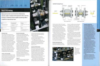
Drop Forging Process
Closed die forging
Ram
Open die forging
Upper die
Hardened 1
steel tool .—.
y-" '-7
metal billet , /
1
1 Metal is
drawn out under
Anv"l
Lower die
Flash
Loading Initial press Loading Completed forging
TYPICAL APPLICATIONS
The high-strength nature of forged metal
parts makes them ideal for demanding
applications and critical components
that require excellent resistance to
fatigue. Forged components are found
in lifting equipment, aerospace, military
applications, cars and heavy machinery.
Many gears, plumbing parts, hand
tools and implements are forged. Car
axles and crankshafts are open die
forged. The heads of nails and bolts are
cold forged.
RELATED PROCESSES
Forging is suitable for one-offs and low
volume production as well as mass
production runs. At low volumes it is an
alternative to CNC machining (page 182),
and at high volumes it competes with die
or Investment casting (pages 124 and 130).
Ring rolling as covered in tube bending
(page 98) produces similar geometries to
roll forging, but they require welding,
whereas roll forged rings are seamless.
QUALITY
By its very nature,forging improves grain
structure in the finished part. Metal
billets go through plastic deformation as
they are forged and as a result the metal
grains align in the direction of flow. This
produces exceptional strength to weight
and reduces stress concentrations that
tend to occur in corners and fillets. Parts
TECHNICAL DESCRIPTION
The drop forging process is carried out
using either a closed or open die. An
open die Is typically used for drawing
out (elongating a part and reducing its
cross-section), upsetting (shortening a
part and increasing its cross-section) and
conditioning (preparing a part for closed
die forging). Open die forging is also used
to shape hexagonal and square section
bars. The tool face is generally square
or v-shaped for simple forming. The
workpiece is repositioned between each
drop of the hammer by the operator. This
requires a great deal of operator skill
and experience and is not suitable for
automation. Long profiles can be forged
in sections.
Closed die forging can be automated
for high volume production. The tools are
fabricated in tool steels (chromium-based
or tungsten-based) or low alloy steels.
The life expectancy of a tool is largely
dependent on the shape of the part, but is
also affected by the ductility of the forging
material. For example, stainless steel
must be heated to over 1250°C (2282°F)
and so stresses and wears the surface
of the tool much more rapidly than
aluminium, which is forged at only 500°C
(932°F). During operation, lubricant that
acts as coolant is applied to the surface of
the tool to cool it down and reduce wear.
In drop forging, the ram brings the
upper die into contact with the workpiece
under great pressure, from 50 kg/m2
to 10,000 kg/m2 (362-72,330 lb/ft2).
The force is generated by gravity fed
weights or by powered means (hydraulic
or compression) forcing the ram down.
Press forging is powered by hydraulic
rams, which force the metal into the
die cavity in a squeezing action. This
technique can be used to process metals
hot or cold. Cold metal forging is typically
used for small parts, no larger than
10 kg (22 lb). The advantage of cold
forging is that it can be used to produce
near net shape parts that do not require
secondary operations.
can be machined post-forging with no
loss of quality because there are no voids
or porosity in the finished article.
The tolerances range from 1 mm
(0.04 in.) in small parts up to 5 mm
(0.2 in.) in large parts,but vary according
to requirements because reducing
tolerances increases costs. Forging is
often combined with machining for
Improved accuracy.
DESIGN OPPORTUNITIES
Forging is suitable for low volume
production and one-offs.This is](https://image.slidesharecdn.com/manufacturingprocessesfordesignprofessionals-231008134532-9d8b1244/85/Manufacturing-Processes-for-Design-Professionals-pdf-59-320.jpg)
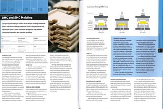
![Forming Technology
Press Braking
This simple and versatile technique is utilized to bend sheet
metal profiles for prototypes and batch production. A range of
geometries can be formed including bend, continuous and sheet,
it is also referred to as brake forming.
Costs
• No cost for standard tooling
• Low to moderate unit costs
Quality
• High quality and accurate bends to within
±0.1 mm (0.004 in.)
Typical Applications
• Consumer electronics and appliances
• Packaging
• Transport and automotive
Related Processes
• Extrusion
• Metal stamping
• Roll forming
Suitability
• One-off to batch production
Speed
• Cycle time of up to 6 bends per minute
• Machine set-up time can be long
INTRODUCTION
Press brakes are fundamental to low
to medium volume metalwork.When
combined with cutting and joining
equipment, press brakes are capable of
producing a range of products including
continuous, bend and sheet geometries.
They tend to be manually operated and
are used for one-off, low volume and
batch production up to 5,000 units.
Pressure is applied by a hydraulic ram,
which forces the metal to bend along
a single axis between a punch and die.
There are many standard punches and
dies, which are used to produce a range
of bends with different angles and
circumferences (see image, opposite),but
always in a straight line.
TYPICAL APPLICATIONS
Press brakes are versatile machines,
capable of bending both thick and thin
sections up to 16 m (52 ft) long. Examples
include lorry sidings, architectural
metalwork, interiors, kitchens, furniture
and lighting, prototypes and general
structural metalwork and repairs.
RELATED PROCESSES
This process tends to be limited to
volumes less than 5,000 parts. Each bend
is another operation andthe machine
has to be set up to accommodate
each bend. While this is not a lengthy
process with modern computer-guided
machinery, every second counts in high
volume production.Thus large volumes
of manufacture often justify processes
with highertooling costs provided they
reduce the number of operations and
cycle time.
Press Braking Process
Hydraulic ram
Workpiece
[blank]
t
Die I
¦>i4
Stage 1: Load Stage 2: Air bending Bottom bending Gooseneck bending
TECHNICAL DESCRIPTION
Press brakes are driven by hydraulic rams,
which apply vertical pressure. The tonnage
required is determined by U factors: bend
length, thickness, tensile strength and bend
radii. Increasing the width of the lower die
increases the bend radii and reduces the
Metal stamping (page 82) can produce
shapes with complex undulating profiles
in a single operation. Design for this
process is very different from that of
press braking.
Metal folding is similar to press
braking: they are both used to form tight
bends in thin sheet materials. Metal
folding machines are often integrated
into a sheet metalworking production
line.They are used in the manufacture of
thin walled metal enclosures, packaging
and electronics housing, for example.
The sorts of geometries that can be made
include squares, rectangles, pentagons,
hexagons and tapered shapes.
Roll forming (page 110) shapes
metal sheet into continuous profiles
with a constant wall section and is
similar to extrusion. Roll forming has
the advantage of being able to process
almost any metal. Extrusion, on the other
hand, is capable of producing hollow
profiles with varying wall thicknesses.
tonnage required to make the form. A typical
press brake of 100 tonnes (110.2 US tons)
will fold 3 m 110 ft) of 5 mm (0.2 in.) steel in a
32 mm (1.26 in.) wide lower die. A narrower
die will require more tonnage.
In stage 1, the prepared workpiece is
loaded onto the die. In stage 2, pressure
is applied by the hydraulic ram so the
punch forces the part to bend. Each bend
takes only a few seconds. Computer-
guided machines reposition themselves
between bends. Alternatively, the same
bend can be made on a batch of parts
before the machine is repositioned for
the next operation.
Right
Many different shapes
of bend can be formed
without investment in
tooling, using standard
punches like these.
QUALITY
Applying a bend to a sheet of material
increases its strength, while bending
processes combine the ductility and
strength of metals to produce parts with
improved rigidity and lightness.
Machines are computer guided,
which means they are precise to within
at least o.oi mm (0.0004 in-) and can
be preprogrammed for any given part.
The geometry of the bend determines
the type of punch and die that are used;
there are many different types, including
air bending dies, V-dies for bottom bending,
gooseneck dies, acute angle dies and
rotary dies. Tools can be laser hardened for
improved durability.
Air bending is used for most general
work such as precision metalwork, while
bottom bending with matched dies (also
called V-die bending or coining) is reserved
for high precision metalwork because it
needs more pressure to operate.Gooseneck
dies are for bending re-entrant angles that
cannot be accessed by a conventional tool.](https://image.slidesharecdn.com/manufacturingprocessesfordesignprofessionals-231008134532-9d8b1244/85/Manufacturing-Processes-for-Design-Professionals-pdf-76-320.jpg)
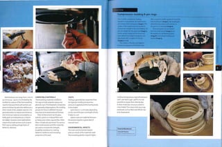
![Forming Technology
Press Molding Ceramics
Ram pressing, jiggering and jolleying are all techniques for
manufacturing multiple replica ceramic parts with permanent
molds. They are used in the production of kitchen and tableware,
including pots, cups, bowls, dishes and plates.
Costs
• Low to medium tooling costs
• Low to medium unit costs, depending on
level of manual input
Quality
• High quality finish
Typical Applications
• Kitchen and tableware
• Sinks and basins
• Tiles
Related Processes
» Ceramic slip casting
» Clay throwing
Suitability
• Low to high volume production
Speed
• Rapid cycle time (1-6 per minute],
depending on level of automation
• Long firing process (up to 48 hours)
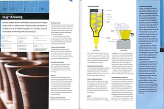
INTRODUCTION
In this process, clay is forced into sheet
geometries using permanent molds,
Parts are compressed and have an even
wall thickness. Press molding is often
em ployed for the mass production of
popular ceramic flatware andtiles.
The 2 main techniques used to
press ceramics are jiggering (known as
jolleying if the mold is in contact with the
outside surface of the part rather than
the inside surface) and ram pressing.
Although both of these processes can be
automated, jiggering andjolleying are
often carried out as manual operations
and can be used only on geometries
that are symmetrical around an axis of
rotation. Ram pressing can be utilized to
make symmetrical shapes as well as oval,
square, triangular and irregular ones.
TYPICAL APPLICATIONS
Uses for press molding ceramics include
flatware (such as plates, bowls, cups
and saucers, dishes and other kitchen
and tableware vessels), sinks and basins,
jewelry andtiles.
RELATED PROCESSES
Clay throwing (pagei68) and ceramic
slip casting (page 172) are used to make
similar products and geometries.
Press molding differs from them by
specializing in high volume and the rapid
production of identical parts.
OUALITY
The pottery materials used in press
molding are brittle and porous (see
ceramic slip casting), so the surface is
often made vitreous by glazing, which
provides a watertight seal.
A very high surface finish can be
achieved with both jiggering and ram
pressing techniques. When compared to
ceramic slip casting and clay throwing,
press molding has the advantage of
producing parts that are uniform and
compressed and therefore less prone
to warpage.
DESIGN OPPORTUNITIES
Jiggering and ram pressing can be used
to produce most shapes that can be
slip cast in a 2 part mold. Using molds
increases repeatability and uniformity
of part, so even tall objects are easily
produced with minimum skill. Manual
operations, such as adding handles and
spouts, ten d to require a hi gher 1 evel of
operator skill.
Ram pressing has the advantage of
being able to produce shapes that are
not rotationally symmetrical. Many
design features (handles and decoration,
for example) can be pressed directly onto
the part to reduce or eliminate assembly
and cutting operations.The part is
pressed and cut in a single operation,
thereby reducing cycle time dramatically.
DESIGN CONSIDERATIONS
The 2 part mold used in ram pressing has
to be made to tight tolerances to ensure
accurate and uniform reproductions. By
contrast, jiggering uses a single mold
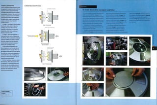
Jiggering Process
Stage 1: Open mold, loading and unloading
Stage 2: Closed mold
andprofiling tool to shape the clay.This
means that jiggering is more suitable for
prototyping and shot production runs.
The heat of the ram press molds
1 e ath er h arden s th e cl ay duri n g th e
pressing cycle, which means that the
part can be removed from the mold
immediately. Jiggered parts, on the
othex hand, have to be left to air dry on
the mold. This causes a problem, in that
many molds have to be used to form
multiple products and these take up a
large amount of storage space.
Shrinkage is in the region of 8%, but
does depend on the type of material.
COMPATIBLE MATERIALS
Clay materials including earthenware,
stoneware and porcelain can be pressed.
Unlike ceramic slip casting, the day is
not watered down for these processes.
However, it is essential that the material
i s suffi ci ently m oi st to fl ow duri n g th e
pressing cycle. The clay used for ram
pressing is slightly stiffen
COSTS
Tooling costs for jiggering are relatively
low because a single sided mold is used.
For volume production multiple tools are
required because the clay has to be left
on the mold to air dry.
Ram pressing uses split molds, which
are in the region of 10-20 times the cost
of jiggering molds. However, they have a
higheryield than jiggering molds, more
rapid turnover and they last many more
cycles (approximately 10,000).
Cycle time is rapid for ram pressing
and slightly slowerfor jiggering.
Automated processes accelerate
production of press moldings.
Labour costs are higher for manual
operations, but for automated
techniques they are relatively low.
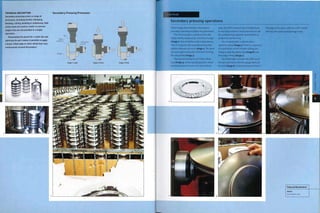
ENVIRONMENTAL IMPACTS
In all pressing operations scrap is
produced at the 'green' stage and so
can be directly recycled. Using molds to
reproduce the parts accurately reduces
TECHNICAL DESCRIPTION
A plaster 'male' mold is used in the
jiggering process and a 'female' one
for the jolleying process. In stage 1, the
mold is mounted onto a metal carrier
attached to an electric motor that spins
at high speed. A charge of mixed clay is
loaded onto the clean mold. In stage 2,
as the mold and clay spin, the jiggering
arm is brought down onto the clay. A
profiled former with a shaping blade,
which is different for each mold shape,
forces the clay to take the shape of the
rotationally symmetrical mold. The
profiled former determines 1 side of
the clay part and the mold determines
the other side. The process is very
rapid and takes less than a minute.
Once the final shape is complete
and the edges have been trimmed, the
mold and clay are removed from the
metal carrier intact. The clay part is
left on the mold until it is sufficiently
'green' to be removed. If the part is
demolded immediately It will deform
because the clay is still very supple.
The length of time is determined by
the weather conditions and ambient
temperature: a hot environment
will cause the clay to dry out more
quickly, if there are secondary
operations to be carried out, such as
piercing or assembly, then the clay
part Is transferred onto a 'female'
support mold.
waste caused by inconsistency.There
are no harmful by-products from these
pottery forming processes.
The firing process is energy intensive,
so therefore the kiln is fully loaded for
each firing cycle.
Finished part trimmed and
removed on the mold for support
Pressure applied to shape the
clay over the plaster mold
Plaster mold rotates at
high speed
— Metal carrier](https://image.slidesharecdn.com/manufacturingprocessesfordesignprofessionals-231008134532-9d8b1244/85/Manufacturing-Processes-for-Design-Professionals-pdf-90-320.jpg)

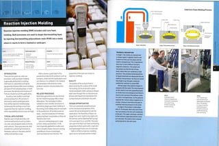
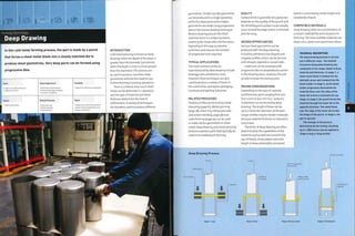
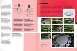
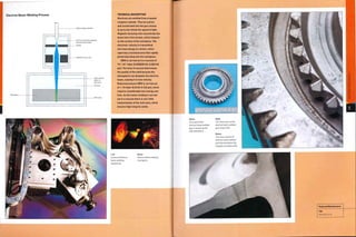
![Spark erosion
Workpiece
Movement in x, y and
z axes
Copper electrode
(tool)
Dielectric fluid
in continuously
running bath
Clamp (+]
TECHNICAL DESCRIPTION
Die sink EDM takes place with the
electrode (tool) and workpiece
submerged in light oil, similar to
paraffin. This fluid is continuously
running and so both maintains the
temperature of the workpiece and
flushes out vaporized material. It Is also
dielectric, which insulates the working
area and sustains the static discharge
within In It.
The copper electrode (tool) and metal
workpiece are brought within close
proximity, which initiates the spark
erosion process. High voltage sparks
leap from the electrode to the workpiece
and vaporize the surface of the metal.
The electrical discharges jump between
the closest points on the electrode and
the workpiece, forming continuous and
even surface material removal.
There is no pressure required in
operation. The electrode is lowered
into the workpiece very gradually,- the
speed of the process is dependent on
the finish required and can range from
2 mm3 (0.00012 in.3) per minute to over
400 mm3 (0.024 in.3) per minute for very
rough finishes. As the tool is sunk into
the workpiece it is continuously agitated
and descends in a spiral. This action
flushes vaporized material away from
the cutting area and ensures even and
efficient material removal.
textures, which are determined by the
machine settings, eliminating the need
for further finishing operations.
These processes can be used to
produce geometries that are not possible
with conventional machining. For
instance, the guide heads on many wire
EDM machines can move independently
during the cutting process.The
advantage is that complex tapers, up to
30°, can be cut with extreme precision,
which is not possible with any other
machining technique.
Die sink EDM can be used to produce
internal geometries on parts that are not
possible with conventional machining.
Die sink EDM Process
D
¦=>
This is because a negative copper
electrode can be machined into shapes
that are not suitable for cavities.The
negative electrode (tool) is reproduced in
the workpiece, creating sharp corners
and complex features that would
otherwise be impractical.The erosion of
the copper electrode (tool) is considerably
slower than the erosion of the workpiece
(0.1%), so small internal radii and
complex features are reproduced to the
same precision as simple geometries.
Wire EDM can be used in much the
same way as hot wire cutting polymer
foam, although it is considerably more
precise andmuch slower,The equipment
requires a high level of skill to operate.
Stress is not applied to the electrode
(tool or wire) or workpiece during
processing because the metal is not
being shaped by force, but in stead by
high voltage sparks that vaporize the
surface. Other than the obvious, this
has many processing advantages. For
example, multiple thin-walled parts can
be stacked up and cut by wire EDM to
reduce processing time.
DESIGN CONSIDERATIONS
Although these processes can produce
internal radii as small as 30 microns
(0.0012 in.), it is always better to use
larger radii to avoid stress concentration.
However, these do not need to be any
larger than 500 microns (0.02 in.) in most
applications.The minimum internal
radius is also affected by the thickness
of the wire electrode, which is typically
50 microns (0.0020 in.) to 300 microns
(0.012 in.) in diameter.
The thickness of material that can
be cut by wire EDM ranges from o.i mm
(0.004 in.) up to 200 mm (7-87 i^-).
but depends on the capabilities of
the equipment.The depth that can be
produced by die sink EDM is limited by
the ease with which vaporized metal
(black powder) can be flushed away, so
maximum depth is affected by the depth
to diameter ratio. Very deep profiles are
possible, but may require extra flushing,
which will increase cycle time.
COMPATIBLE MATERIALS
Many metals can be shaped by EDM
techniques.The hardness of the material
does not affect whether it can be
processed in this way. Metals including
stainless steel, tool steel, aluminium,
titanium, brass and copper are
commonly shaped in this way.
COSTS
Wire EDM does not require tooling.
However, it does consume wire electrode
continuously, which must be replaced.
Case Study
Die sink EDM
This process is widely used for tool-making. As
well as machining entire cavities for injection
molding, it is often used to modify existing
tools. It can also be used to bore holes or
emboss surface textures and graphics. In this
case study, Hymid Multi-Shot are forming a
cavity directly into the surface of high-carbon
steel (image 1). It is not practical to machine
complex and intricate cavities into hard
metals like this, other than by using EDM.
The copper alloy electrode (tool) is inserted
into a tool holder that is registered with
the computer guided tool head (image 2).
The EDM machines are programmed to the
settings required forthe tool.The black areas
show the parts of the tool that have been
exposed to spark erosion. Each tool may last
for only 5 uses before it has to be replaced.
If extreme levels of precision, to within
5 microns (o.oooig in.), are required, new
tools are machined for each EDM operation.
including a tool for roughing out and a
separate tool for finishing.
The tool and workpiece are inserted and
submerged in a dielectric fluid, which is
similar to paraffin (image 3). In fact, paraffin
was once used as the insulating fluid, until
this oil was developed.
Sparks and fumes are given off during
rough cutting (image 4). The copper electrode
is charged with an electric current, which
jumps to the oppositely charged workpiece
when they come into very close proximity.
There are several thousand sparks per
second. Each spark vaporizes a small piece
of surface material. The arcs will jump
across the shortest distance between the
electrode and workpiece, which ensures
evenly distributed surface removal. In this
case the process is vaporizing around 400
mm3 (0.024 in.3) per minute. The resulting
surface finish is very rough (image 5).
The second stage of machining is
much slower, in this case as low as 50 mm3
(0,003 in.3) per minute (image 6), This
produces a much finer surface texture
(image 7), This is a very shallow impression;
die sink EDM can also be used to form very
deep cavities.
cs
m
o
o
>
r~
o
CD
o
X
>
O
>
O
in
Featured Manufacturer
Hymid Multi-Shot
www,hymid,co,uk](https://image.slidesharecdn.com/manufacturingprocessesfordesignprofessionals-231008134532-9d8b1244/85/Manufacturing-Processes-for-Design-Professionals-pdf-130-320.jpg)
![RFW. LFW and OFW: No tooling costs
FSW: Inexpensive tooling costs
Low to moderate unit costs
Typical Applications
• Aerospace
• Automotive and transportation
• Shipbuilding
Suitability
• High volume production
Quality
• High integrity hermetic seal
• High strength joint that can have similar
characteristics to base material
Related Processes
• Arc welding
• Power beam welding
• Resistance welding
Speed
• Rapid cycle time that depends on size
of joint
Forge welding processes are used to form permanent joints in
metals. There are U main techniques: rotary friction welding
(RFW), linear friction welding (LFW), orbital friction welding
(OFW) and friction stir welding (FSW).
INTRODUCTION
The 4 main friction welding techniques
can be separated into 2 groups:
conventional techniques including LFW,
OFW and RFW processes; and a recent
derivative, FSW.
LFW, OFW and RFW operations weld
materials with frictional heat generated
by rubbing the joint interface together.
The joint plasticizes and axial pressure is
applied, forcing the materials to coalesce.
The rotary technique (see main image)
was the earliest and is the most common
of the friction welding techniques.
In FSW the weld is formed by a
rotating non-consumable probe (tool),
which progresses along the joint mixing
the material at the interface (see image,
page 396, above left).
TYPICAL APPLICATIONS
Application of these processes is
concentrated in the automotive,
transportation, shipbuilding and
aerospace industries.
In the automotive industry, RFW is
usedfor critical parts including drive
shafts, axles and gears. LFW is utilized to
join engine parts, brake discs and wheel
rims. OFW has not yet found commercial
application in metals, but is utilized
in the plastics industry (see vibration
welding, page 298). FSW is used to join
flat panels, formed sheets, alloy wheels,
fuel tanks and space frames.
The first commercial application of
FSW was in the shipbuilding industry,
for welding extruded aluminium
profiles into large structural panels.
This has benefits for many industries:
for example, the railway one, in the
construction of prefabricated structural
components in train carriages (see
images, page 297, above, top right and
above right). FSW is suitable as it causes
very little distortion in the welded parts,
even across long joints in thin sections.
Recently, FSW has been introduced
into the consumer electronics industry,
such as in the fabrication of Bang &
Olufsen aluminium speakers (see
images, page 297, above left and left).
RELATED PROCESSES
Even though the welds are of similar
quality, friction welding is not as widely
used as arc welding (page 282) and
resistance welding (page 308).This
is mainly because it is a more recent
development: for example,TWI patented
friction stir welding only in 1991. It is also
because friction welding is a specialized
technique, and the equipment costs are
extremely high.
Friction welding does not take the
weld zone above melting point, so this
process can join metals that are not
suitable for fusion welding by arc or
power beam welding (page 288).
Friction welding plastics is known as
vibration welding (page 298).
QUALITY
Friction welding produces high integrity
welds. Butt joints are fused across the
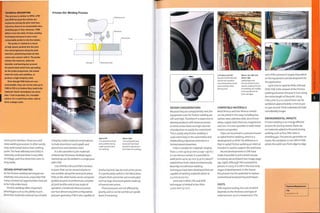
Friction Welding
Processes
Rotary friction welding
Stage 1: Load
Plasticized metal
Stage 2: Friction through rotation
Weld flash
Stage 3: Axial pressure
Linear friction welding
CLamps Workpiece
Stage 1: Load
Interface plasticizes
Reciprocating
motion
Stage 2: Friction through j Axial pressure
rubbing
Weld flash
Stage 3; Axial pressure
Axial pressure
Above
This titanium blistc
(i-piece bladed disc) for
]et engines is made by
linear friction welding.
Right
These beech blocks have
been joinedby linear
friction welding.
Another technique uses stored energy
and is known as inertia friction welding.
In this process the spinning workpiece
is attached to a flywheel. Once up to
speed, the flywheel is left to spin freely.
The parts are brought together and the
stored energy in the flywheel spins the
parts sufficiently for a weld to form. The
process Is similar to RFW, except that a
mandrel Is used to maintain the Internal
diameter of the pipe.
LFW and OFW are based on the same
principles as RFW. However, instead of
rotation, the parts are oscillated against
one another. In stage 1, the 2 workpleces
are clamped. In stage 2, the joint Interface
is heated by rubbing the parts together.
In stage 3, axial force Is Increased and
maintained until the joint has formed.
LFW typically operates at frequencies
up to 75 Hz and amplitudes of ±3 mm
10.118 in.). These processes were
developed for parts that are not suitable
for rotary techniques.
TECHNICAL DESCRIPTION
The use of RFW Is limited to parts where
at least 1 part Is symmetrical around
an axis of rotation. In stage 1, the 2
workpleces are secured onto the chucks.
In stage 2,1 of the parts is spun while
the other is stationary. They are forced
together, and friction between the 2
faces causes the metal to heat up and
plastlclze. In stage 3, after a specified
time - a minute or so - the spinning
stops and the axial force Is Increased to
20 tonnes or so. Flash forms around the
circumference of the joint and can be
polished off afterwards.](https://image.slidesharecdn.com/manufacturingprocessesfordesignprofessionals-231008134532-9d8b1244/85/Manufacturing-Processes-for-Design-Professionals-pdf-149-320.jpg)
![Joining Technology
Vibration Welding
Homogenous bonds in plastic parts can be created using
vibration welding. Rapid linear or orbital displacement
generates heat at the interface, and this melts the joint material
and forms the weld.
Low to moderate tooling costs
Low unit costs
Typical Applications
• Automotive
• Consumer electronics
• Packaging
Suitability
• Medium to high volume production
INTRODUCTION
Vibration welding is based on friction
welding (page 294) principles.The
parts are rubbed together to generate
frictional heat, which plasticizes the
joint interface. The process is carried out
as linear or orbital vibration welding.
Linear vibration welding uses transverse,
reciprocating motion - the vibration
occurs in only 1 axis. Orbital vibration
welding uses constant velocity motion
- a non-rotating offset circular motion
in all directions.The vibration motion
occurs equally in both the x andy axes
and all axes in between.
TYPICAL APPLICATIONS
Although this process is typically utilized
in the automotive industry, it is now
steadily becoming more widespread in,
for example, medical, consumer
electronics and white good appliances.
ssisr
Speed
• Very rapid cycle time (up to 30 seconds]
Quality Related Processes
• Friction welding
• Hot plate welding
• Ultrasonic welding
Vibration Welding Process
RELATED PROCESSES
Linear friction welding metal and linear
vibration welding plastic are the same
process; both join parts by rubbing them
together using linear motion, under axial
force. Ultrasonic welding (page 302) and
certain adhesive technologies are
frequently an alternative, especially for
thin walled and delicate parts.
Ultrasonic welding transfers energy
through the part to thejoint interface.
By Contrast, the Vibration process
transfers energy directly to thejoint
interface, so does not rely on the ability
of the part material to transmit energy.
Fillers, regrind, colour additives and
contamination all affect a material's
ability to transmit energy and so reduce
the effectiveness of ultrasonic welding
but not vibration welding.
Recent developments include heating
the joint interface prior to welding, in a
process similar to hot plate welding
(page 320). Combined, these processes
create neat and high strength welds with
much less debris, especially important
for such applications as filter housings.
QUALITY
Vibration welding produces strong
bonds. It is possible to form hermetic
seals for automotive and packaging
applications. When certain material
combinations are joined in this way a
complete mixing of the materials occurs,
resulting in a homogenous bond.
Further variables to influence
weldability include moisture content and
the addition of resin modifiers.
Stage 2: Closed mold, welding and clamping
TECHNICAL DESCRIPTION
In stage 1 of linear vibration, 1 part Is
placed in the lower platen and the part
to which it is to be joined is positioned
in the upper platen. In stage 2, the heat
necessary to melt the plastic is generated
by pressing the parts together and
vibrating them through a small relative
displacement from 0.7 mm to 1.8 mm
(0.028-0.071 in.) at 240 Hz or a 4 mm
(0.016 in.) peak to peak at 100 Hz in the
plane of the joint under a force of
1-2N/mm2 (0.69-1.37 psi).
Heat generated by the resulting
friction melts the plastic at the interface
within 2-3 seconds. Vibration motion
is then stopped and the parts are
automatically aligned. Pressure is
maintained until the plastic solidifies
to bond the parts permanently with a
strength approaching that of the parent
material itself.
During orbital vibration welding, each
point on the joint surface of the moving
part orbits a different and distinct point
on the joint surface of a stationary part.
The orbit Is continuous and of constant
speed, identical for all points on
the joint surface. The movement's
orbital character Is produced by three
electromagnets arranged horizontally at
relative angles of 120°. These magnets
Influence the movement of the fixture
and generate a harmonic movement.
Compensation for the decreasing force
of one electromagnet is provided by
attraction of the next electromagnet,
together with a change in direction. This
causes rotary vibration of the fixture,
which ensures a controlled relative
movement in a frequency between
190 Hz and 220 Hz and an amplitude
range between 0.25 mm and 1.5 mm
(0.1-0.59 in.) peak to peak.](https://image.slidesharecdn.com/manufacturingprocessesfordesignprofessionals-231008134532-9d8b1244/85/Manufacturing-Processes-for-Design-Professionals-pdf-151-320.jpg)
![Joining Technology
Resistance Welding
These are rapid techniques used to form welds between 2 sheets
of metal. Spot and projection welding are used for assembly
operations, and seam welding is used to produce a series of
overlapping weld nuggets to form a hermetic seal.
Costs
• Low tooling costs, if any
• Low unit costs
Typical Applications
• Automotive
• Furniture and appliances
• Prototypes
Suitability
• One-off to mass production
^ Quality Related Processes
h • High shear strength, low peel strength 'Arc welding
I • Hermetic joints possible with seam • Friction welding
I welding • Riveting
Speed
• Rapid cycle time
INTRODUCTION
All of the resistance welding techniques
are based on the same principle: a high
voltage current is passed through 2
sheets of metal, causing them to melt
and fuse together.
As the name suggests, these processes
rely on metal's resistance to conducting
electricity. High voltage, concentrated
between 2 electrodes, causes the metal
to heat and plasticize. Pressure applied
during operation causes the melt zone to
coalesce and subsequently form a weld.
The 3 main resistance welding
processes are projection, spot and seam.
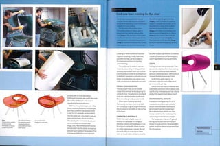
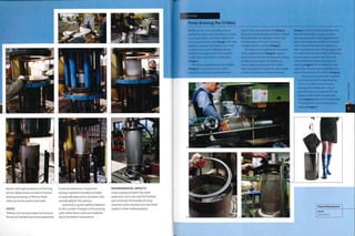
Projection Welding Process
Electrode (+] j
Electrode (-)
Stage 1: Load
TECHNICAL DESCRIPTION
In projection welding, the weld zone is
localized. This can be done in 2 ways; either
projections are embossed onto 1 side of the
joint, or a metal insert is used.
This process is capable of producing
multiple welds simultaneously because
unlike spot welding the voltage is directed
by the projection or insert. The electrodes
do not determine the size and shape of the
weld. Therefore, they can have large surface
area that will not wear as rapidly as spot
welding electrodes.
Stage 2; Clamp
and weld
Stage 3: Unload
These are used in many sheet metal
industries, but most importantly in
automotive construction,They have
been fundamental in the development
of mass produced cars: operating at high
speeds they are suitable for both manual
and automated application. A single car
may have up to 4,000 spot welds holding
its metalwork together.
TYPICAL APPLICATIONS
Applications are widespread, including
the automotive, construction,furniture,
appliance and consumer electronic
industries.These processes are used for
prototypes as well as mass production.
Above Left
The ring is placed onto a
lower electrode, which
locates it to ensure
repeatable joints.
Above
The second part has
protrusions that
localize the voltage.
It is clamped into the
upper electrode.
Right
Projection welding
takes a second or so.
Both welds are formed
simultaneously and are
full strength almost
immediately.
Spot and projection welded products
include car chassis and bodywork,
appliance housing, electronic circuitry,
mesh and wire assembly.
Seam welding is used on products
such as radiators, gas and water tanks,
cans, drums and fuel tanks.](https://image.slidesharecdn.com/manufacturingprocessesfordesignprofessionals-231008134532-9d8b1244/85/Manufacturing-Processes-for-Design-Professionals-pdf-156-320.jpg)
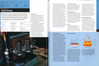
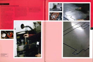
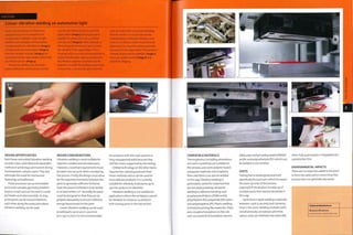
![Spot Welding Process
Electrode (+) .
I f I
I 1 i ® 1 i
Stage 1: Load Stage 2: Clamp
and weld
1}
i ! j
Electrode I-) i BB BH
Stage 3; Unload
TECHNICAL DESCRIPTION
Spot welding is the most versatile of the
resistance welding processes. The weld zone
is concentrated between 2 electrodes that
are clamped onto the surface of the metal
joint. Very high voltage plasticizes the metal
and pressure is applied, forcing it to coalesce
and subsequently form a weld nugget.
Because the weld is concentrated
between the electrodes only 1 weld can
be produced with each operation. Multiple
welds are produced in sequence.
Equipment is generally not dedicated,
so this process is the least expensive and
the most suitable for prototyping and low
volume sheet metal work.
Lett
Spot welding stainless
steel mesh with a hand
held welder and larger,
static lower electrode.
Below lett
The welded mesh covers
a paper pulp molding
tool (page 202).
Above
Heavy duty handheld
welding guns like this
are used for general
sheet metal assembly
work. Sophisticated
computer-guided
robotic systems are
used for high volume
welding operations.
RELATED PROCESSES
Resistance welding stands alone in
the welding techniques: it is simple,
consistent, low cost and de-skilled. Arc
welding (page 282) and power beam
welding (page 288) require ahigh level of
skill to operate with such efficiency.
Formed and riveted joints require
preparation. Resistance welding can
be applied with very little surface
preparation. Weld nuggets are formed
easily in most metals, regardless of
theirhardness. Slightly higher clamping
pressures are required when welding
harder materials to achieve the same
level of coalescence.
Seam Welding Process
c?=C>
Electrode (+]
Electrode (¦
QUALITY
Weld quality is consistently high. Joints
have high shear strength, but peel
strength can be limited with small and
localized weld nuggets,
DESIGN OPPORTUNITIES
These are simple and versatile processes.
Spot welding is widely available for
prototyping sheet metal work; it is
relatively inexpensive and can be used on
a range of materials,
Dissimilarmetals can bejoined
together, although the strength of the
joint may be compromised. Also, different
thickness of material can bejoined
together, or multiple sheet materials
laid on top of each other. Assemblies up
to 10 mm (0.4 in.) deep can bejoined
with a single spot weld, but thickness is
generally limited to between 0.5 mm and
5 mm (0.02-0,2 in.).
DESIGN CONSIDERATIONS
The position of the weld is limited
by 2 factors;the reach of the welding
equipment and the shape of the
electrode. Theform of atypical handheld
spot welding gun (see image, opposite,
above) makes clear the constraints.
The weld point must be accessible
from the edge of the sheet. Welding
equipment typically operates on a
vertical axis, so weld points must be
accessible from above and below. Even so,
it is possible to weld in confined spaces
with offset or double bent electrodes,
COMPATIBLE MATERIALS
Most metals can bejoined by resistance
welding, including carbon steels,
stainless steels, nickels, aluminium,
titanium and copper alloys,
COSTS
Tooling costs are not always a
consideration: many joints can be welded
with inexpensive standard tooling.
Specially designed tooling maybe
required to weld contoured surfaces, but
is generally small and not expensive.
Most assemblies can be welded with
standardelectrodes (tooling),which
minimizes costs. However, certain
applications, including contoured
surfaces, require dedicated electrodes.
Cycle time is rapid. Spot welding can
only produce 1 weld at atime and so
islimitedtoabouti weldpersecond.
Projection welding can produce multiple
welds simultaneously, so is more rapid.
The speed is affected by changes in
material thickness, welding through
coatings and variability in part fit up.
TECHNICAL DESCRIPTION
Seam welding is a continuous process in
which the welding occurs between rolling
electrodes. It is possible to form hermetic
joints in sheet metal using this technique.
An alternative technique is used to apply
multiple spot welds in a line. This is done
by replacing the rolling electrodes with
wheels that have a single electrode on the
perimeter, which produces a spot weld when
the upper and lower electrodes are aligned.
This technique is used for high volume
production of metal radiators, for example.
ENVIRONMENTAL IMPACTS
No consumables (such as flux,filler or
shielding gas) are required for most
resistance welding processes. Water
is sometimes used to cool the copper
electrodes, but this is usually recycled
continuously without waste.
There is no waste generated by the
process itself, and spot welding does not
require any preparatory or secondary
operations that create waste.](https://image.slidesharecdn.com/manufacturingprocessesfordesignprofessionals-231008134532-9d8b1244/85/Manufacturing-Processes-for-Design-Professionals-pdf-157-320.jpg)
![Joining Technology
Joinery
Contemporary furniture is constructed with both handmade and •L
machine made joints. There are many different types, and it is up
w
to the joiner to select the strongest and most visually pleasing ¦/ ,
for each application.
Costs Typical Applications Suitability
• No tooling costs; jigs may be necessary
• Moderate to high unit costs depending on
the complexity
• Construction
• Furniture and cabinet making
• Interiors
• One-off to high volume production
1
Quality Related Processes Speed
|
_ • Friction welding
• Timber frame construction
• Cycle time depends on complexity
' '¦]
INTRODUCTION
Joinery remains an essential part of
furniture and cabinet making. Craft and
industry have combined over the years
and as a result a standard selection
of joint configurations have emerged.
These include butt, lap, mitre, housing,
mortise and tenon, M-joint, scarf, tongue
and groove, comb,finger and dovetail.
Additionally, butt joints are strengthened
with dowels or biscuits.
All of these joints can be further
reinforced with screws and nails, but this
section is dedicated to joints that are
secured only with adhesive. (For metal
fixtures in timber frame construction,
see pages 344-7.)
Joints have to work both functionally
and decoratively.The art of joinery
is using wood to its strengths. It is
ani sotropi c an d i s stron g er al on g th e
length of its grain. It is alsoproneto
shrinking or expanding as it dries or
absorbs water from the atmosphere.
Therefore, the joint design must be
sympathetic to the strengths and
instabilities of this natural material.
Joints can be seamless and almost
invisible, or they can provide contrast to
emphasize the joint.These are decisions
made by the designer and made possible
by a skilled joiner.
TYPICAL APPLICATIONS
Joinery is used in woodworking
industries, including furniture and
cabinet making, construction, interiors,
boat building andpatternmaking.
Typical furniture includes tables,
chairs, desks, cabinets and shelves.
Joinery is used in construction for timber
roof trusses, gable ends, doors and
window frames. Interior applications
for this process include floors, walls,
structures and stairwells.
RELATED PROCESSES
Joinery and timber frame structures
(page 344) overlap. Simple joinery
is used a great deal in timber frame
construction, especially if the joints
are on display. Buttimberframe
construction tends to be concerned with
speed of operation and reliability of joint.
Metal fixtures are often used, rather than
spending time cutting a complex joint.
The advantage of gluing is that it
spreads th e 1 oad over the entire joint and
is not visible from outside.
In the future, linear friction
welding (page 294) may compete with
conventional gluing techniques.
QUALITY
The quality of joint is very much
dependent on skill.There is very
little room for error, but mistakes are
inevitable. Skilled cabinet makers
differentiate themselves by their ability
to repair mistakes imperceptibly.
Products made from wood have
unique characteristics associated
with visual patterns (growth rings),
smell, touch, sound and warmth. High
quality woodwork is often left exposed.
Joint Configurations
TECHNICAL DESCRIPTION
The diagram illustrates the most common
joint types. They include handmade and
machine made configurations, which are
used in furniture construction, house
building and interior structures.
There are U main types of adhesive,
which are urea polyvinyl acetate (PVA),
formaldehyde (UF), 2-part epoxies and
polyurethane (PUR). PVA and UF resins are
the,least expensive and most widely used.
PVA is water based and non-toxic, and
excess can be cleaned with a wet cloth. PUR
and 2-part epoxies can be used to join wood
to other materials, such as metal, plastic or
ceramic, and are waterproof and suitable for
exterior use. They are rigid, so restrict the
movement of the joint more than PVA.
Butt joints are the simplest form of
joinery. They are inexpensive to prepare
because the 2 planks are simply cut to
length. However, they are also the weakest
because there is a relatively small interface
for gluing and 1 face is end grain. End grain
is the least strong face for all fixing types,
including adhesives, nails and screws.
Butt joints are reinforced with dowels,
biscuits or metal fixings. The benefit of
these is that they are concealed within the
joint interface. These are widely used in high
volume production and flat pack furniture.
A mitre joint is a simple, neat method of
joining 2 planks at right angles. It is more
aesthetically pleasing than a butt joint
because it ensures continuity of long grain
and avoids exposed end grain.
A lap joint increases the size of the
interface to include gluing to long grain on
both sides. This increases the strength of the
joint and requires more preparation.
A comb joint (also called a finger joint)
provides a much larger gluing area and is a
common joint for boxes or drawers in tables
and cabinets. It is made by a series of spaced
cutters on a spindle molder, a spinning
cutter for profiling lengths or ends of wood.
Dovetail joints are modified finger joints.
They are cut with re-entrant angles, which
increase the strength of the joint In certain
directions. They are especially useful for
drawers, which are repeatedly pulled and
pushed from the front.
A housing joint is a lap joint in the middle
of a workpiece. It is common for shelves and
cabinet making.
Mortise and tenon joints are used to join
perpendicular lengths of wood. The leg is the
tenon and the mortise the hole. The tenon is
usually cut on a band saw, and the mortise
on a mortiser, which is a machine with a drill
bit inside a chisel that cuts square holes in
wood. Alternatively, the mortise can be cut
by hand. There are many different types
including haunch, shoulder, blind, through
(illustrated) and pegged.
Scarf joints, tongue and groove, M-joints
and finger joints are primarily used to join
planks of wood to make larger boards.
They increase the gluing surface between
2 planks in a butt joint configuration.
M-joints are machine-made and suitable
for mass production. They are cut on a high¬
speed spindle molder.
The finger joint is machine-made and
designed to integrate lengths of timber
into a continuous profile. It is designed to
maximize gluing area and joint strength.
There are many variations on each of
the above joints, including the angle of
interception and whether the joint detail
penetrates right through the wood or is blind
(not right through).](https://image.slidesharecdn.com/manufacturingprocessesfordesignprofessionals-231008134532-9d8b1244/85/Manufacturing-Processes-for-Design-Professionals-pdf-164-320.jpg)
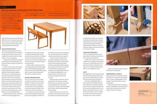
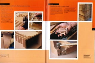
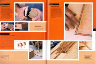
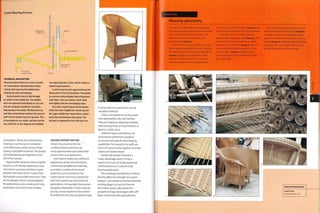
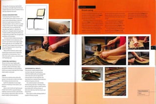
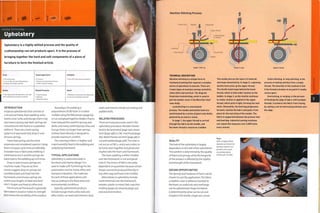
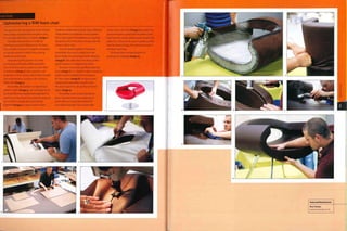
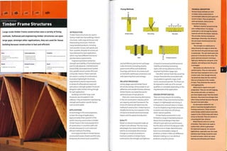
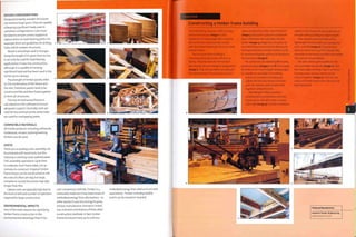
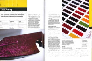
![Spray Coating Process
Workpiece Topcoat
or lacquer
Spray mist Paint supply
Rotating table
or support jig
Spray gun Manually
operated
TECHNICAL DESCRIPTION
Spray guns are gravity fed, suction
fed or pressure fed. The diagram
illustrates a gravity-fed gun. They all
use a jet of compressed air to atomize
the paint into a fine mist. The trigger
controls the valve through which the
pressurized air flows. The atomized
paint is blown out of the nozzle and
makes a cone shape. Pressurized air
is blown out of the cap onto the cone,
which forces it into an elliptical shape.
This gives the operator more control
because the shape can be adjusted to
suit the application and required film
thickness. The coating is applied onto
the surface in overlapping strokes.
Suction feed guns have the paint
pot on the underneath instead of
on top. The paint is drawn into the
jet of air by suction. Pressure feed
systems are supplied by a paint pot
that is connected to the spray gun via a
flexible pipe. The paint is pressurized
to force it into the spray gun.
However, paint is not integral to the
surface and so is prone to peeling and
flaking.This is often the result of pinholes
or porosity in the coating, which allows
the surface of the workpiece to corrode
underneath.
Some aesthetic problems include
'pebbling', 'orange peeling',runs and
sags. Pebbling is caused by a coating that
is too dry; the thinner evaporates before
it has had a chance to settle and smooth.
Water borne paints are prone to orange
peeling. As the name suggests, it is when
the surface resembles orange peel. It is
caused by the coating not flowing on the
surface, or improper paint thinning. Runs
and sags occur when there is too much
wet coating material.
DESIGN OPPORTUNITIES
There is an almost unlimited range of
colours and finishes for paints. Standard
colour ranges include RALand Pantone.
Colour is supplied by pigments,
which are solid particles of coloured
material.They can be replaced or
enhanced by platelets of metallic,
pearlescent, dichroic, thermochromic or
photoluminescent materials.
Entire surfaces can be painted,
including different materials, to produce
a seamless finish. Otherwise, masks and
templates can be used to create different
colours, patterns, logos and text. Masks
and templates can be made from tape,
paper or cardboard for example.
There are many different techniques
used to apply decorative effects. For
example, overlaying colours and tones
using different spraying techniques
will produce graduation, shading and
mottling. Marbling is achieved by
draping materials over a wet topcoat,
which drags and smears it over the
basecoat. Covering it with a clear topcoat
seals in the pattern with dramatic effect
(see image, page 350).
A flock finish can be achieved by
spraying adhesive followed by fibres of
cotton, paper, silk or similar material.
There is even a varnish employed
to produce a cracked topcoat. Crackle
varnish is painted over a colour. Onto this
is applied a contrasting colour, typically
g ol d on top of bl ack. Th e crackl e varn i sh
allows the topcoat to crack but not peel
as it dries and contracts.The effect is
similar to antique gold leaf.
DESIGN CONSIDERATIONS
The opportunities for paint effects and
quality are heavily dependent on the
skill of the operator. With the correct
preparation and basecoat almost any
combination of materials can be coated.
An important consideration is that
spraying applies coatings in line-of-sight,
so deep undercuts and recesses are more
difficult to coat evenly. Electrostatic
techniques draw more spray to the
surface, but there is always overspray.
There is no size restriction. If the part
will not fit in a spray booth or cannot be
moved then it can be sprayed on site.
For example, very large aeroplanes are
Conventional spray guns operate at
approximately 3.45 bar (50 psi). This
depends on the type and viscosity of paint.
Painted surfaces are nearly always made
up of more than 1 layer. If necessary the
surface is prepared with filler and primer.
The primer may provide a surface onto
which paint will adhere such as an acidic
etch primer used to make a good bond with
metallic surfaces. Some topcoats require
a basecoat to provide a coloured backdrop.
Opaque topcoats can be applied directly onto
the primer.
Paints are made up of pigment, binder,
thinner and additives. The role of the binder
is to bond the pigment to the surface being
coated. It determines the durability, finish,
speed of drying and resistance to abrasion.
These mixtures are dissolved or dispersed
in either water (water bornel or a solvent
(solvent bornel.
The ingredients of varnish, lacquer and
paint are essentially the same. Lacquers and
varnishes can be pigmented, tinted or clear.
Another type of paint, 2-pack, has
emerged. They are so called because they
are made up of 2 parts, the resin and the
catalyst or hardener. They are thermosetting
and bond to the surface in a 1 -way reaction.
They are also hazardous to use because they
contain isocyanates.
Water-borne paints are made up of
pigment and a binder of acrylic emulsion,
vinyl emulsion or polyurethane, dissolved or
dispersed in water. They are applied to the
surface and dry as the water evaporates and
the binder adheres to the workpiece. They
are flexible and so are suitable for painting
wood and other materials that are likely to
expand and contract In their lifetime.
Solvent-borne paints (also known as
alkyd and oil-basedl are made up of pigment
and a binder of alkyd resin dissolved in
thinners. Solvent-based paints are slow
drying and off-gas polluting and harmful
volatile organic compounds (VOCs).
Additives provide specific qualities such
as quick drying, antifouling, anti-mould or
antimicrobial properties.
There are 2 different types of enamel
painting. The first is similar to the above,
except that it is a mixture of paint with a high
level of lacquer, which produces a high gloss
finish. The second Is applying a coating of
glass, which is bonded onto the surface of
the workpiece at high temperatures (above
the melting point of the glass]. This limits
the finish to materials with a higher melting
point ceramics and metal, for instance.
sprayed in booths that are modified
aircraft hangers.
COMPATIBLE MATERIALS
Almost all materials can be coated with
paint, varnish and lacquer. Some surfaces
have to be coated with an intermediate
layer, which is compatible with both the
workpiece and topcoat.
Enamel paints that contain glass are
only suitable for high-melting-point
materials such as ceramics and metal.
COSTS
Tooling is not required. However,]igs or
framework may be necessary to support
the workpiece during spraying.
Cycle time is rapid but depends on the
size, complexity, number of coats and
drying time. A small consumer electronic
product may be complete within 2 hours;
in contrast, a car may take several days.
Automated spraying techniques are
very rapid. The parts are sprayed as the
productis assembled to avoidmasking.
All surface coatings are left for at least
12 hours to harden fully. Water borne
paints and varnishes will dry in 2-4
hours. Solvent borne products will take
roughly 4-6 hours.
Labour costs are typically high
because these tend to be manual
processes, and the skill of the operator
will determine the quality of the finish.
ENVIRONMENTAL IMPACTS
Solvent borne paints contain volatile
organic compounds (VOC). Since the
ig8os automotive manufacturers have
been making the switch to water-based
paint systems to reduce their VOC
emissions. It was not until the late 1990s
that water-based systems were capable
of producing a finish that equalled the
previous solvent-based technologies.
Water-based paints are less toxic and
easily cleaned with water.
Spraying is usually carried out in a -
booth or cabinet to allow the paints
to be recycled and disposed of safely.
One system uses running water, which
catches the overspray and transfers it
to a central well where it settles and
separates ready for treatment.](https://image.slidesharecdn.com/manufacturingprocessesfordesignprofessionals-231008134532-9d8b1244/85/Manufacturing-Processes-for-Design-Professionals-pdf-178-320.jpg)
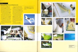
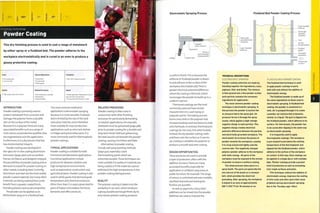
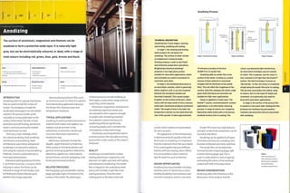
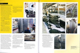
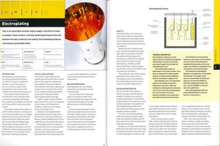
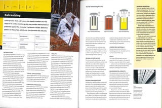
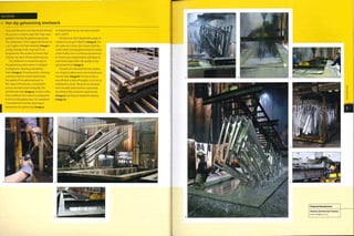
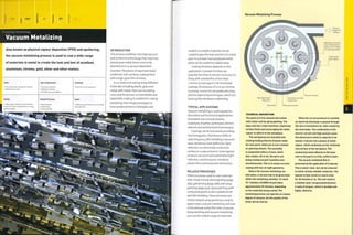
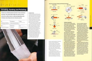
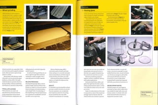
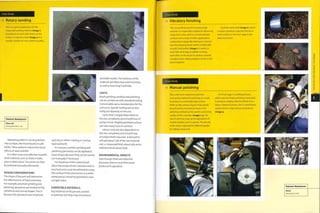
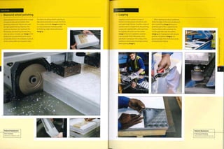
![Case Study
Decorative sand blasting
The glass vesse] being decorated here was
designed by Peter Furlonger in 2005. It was
shaped by glassblowing (see page 152). For
this project, sand blasting has been used to
decorate the surface of the workpiece with
a multilayered artwork.The same principle
can be used to apply decorative patterns to
surfaces, except the wax resist is replaced
with masking.
Firstly, the artwork or pattern is
translated onto a wax resist, either by hand
or by printing (image 1) and applied to the
workpiece (image 2). Negative etching is
used to describe the process of etching
the image and leaving the background
intact. This case study is an example of
positive etching because the image is left
intact and the background is textured.
Once the wax resist has been applied,
the inside surface is masked to avoid
damaging it with the abrasive (image 3).
COMPATIBLE MATERIALS
This process is most effective for etching
metal and glass surfaces, but can be used
to prepare and finish most materials
such as wood and some polymers.
COSTS
There are no tooling costs. However,
masks maybe required, the cost of which
Is affected by the complexity and size of
the area to be abrasive blasted.
Cycle time is good, but is slowed down
by complex masking and multilayerlng.
Automation of simple tasks will greatly
improve cycle time.
For manual operation labour costs are
relatively high.
ENVIRONMENTAL IMPACTS
The dust that is generated during
abrasive blasting can be hazardous.
Booths and cabinets can be used
to contain the dust that Is created,
otherwise breathing apparatus will be
required, much the same as those used
i
The product is held in a glove box with
protective gloves. The operator (artist)
carefully etches away the unprotected areas
of the workpiece with virgin aluminium
oxide, ranging from 180 grit to 220 grit
(image 4). Once the first stage of etching Is
complete, specific areas of the wax resist are
removed, and other delicate areas have their
protection reinforced (image 5). This will
enable the artist to create a multilayered
etched image. This technique is particularly
effective on this product because the coloured
surface has been built up in layers, in that
the top layer has been fired with a blowtorch
to produce metallic effect, the layer
underneath is non-metallic and the base
layer Is clear glass.
The product is returned to the booth
for the second stage of the etching process
(image 6). Finally the wax resist and all other
masking is removed to ready the workpiece
for cleaning and polishing (image 7).
Featured Manufacturer
The National Glass Centre
www.nationalglasscentre.com
for spray painting (page 350) and other
hazardous finishing processes.
Working in a sealed booth means that
the blast materials can be reclaimed
easily for re-use. Attaching a vacuum
system to the blast head makes It
possible to reclaim spent material for
field stripping applications.](https://image.slidesharecdn.com/manufacturingprocessesfordesignprofessionals-231008134532-9d8b1244/85/Manufacturing-Processes-for-Design-Professionals-pdf-197-320.jpg)
![JSi m
Finishing Technology
Photo Etching
This is surface removal by chemical cutting. It has a similar
appearance to abrasive blasting. The surface of the metal is
masked with a resist film and unprotected areas are chemically
dissolved in a uniform manner.
=5 Costs
Low cost tooling
Moderate to high unit costs
Quality
• Prolonged exposure to chemical attack will
cause undercutting
Typical Applications
• Jewelry
• Signage
• Trophies and nameplates
Competing Processes
• Abrasive blasting
• CNC machining and engraving
• Laser cutting and engraving
Suitability
• Prototype to mass production
Speed
• Moderate cycle time, typically
50-100 microns (0.002-0.0039 in.]
per pass (5 minutes)
INTRODUCTION
Photo etching, also referred to as acid
etching and wet etching,is the process of
surface removal by chemical dissolution.
This process is precise andlow cost.
Phototooling is printed acetate, which is
inexpensive to replace.The accuracy of
the etching is determined by the resist
film, which protects areas of the sheet
that will remain unchanged.
Surface removal is slow, typically
50-100 microns (0.0020-0.0039 in.) in
a 5 minute pass. Depths of 150 microns
(0.0059 in ) are suitable for decorative
applications. Patterns, text and logos can
be filled with colour.
TYPICAL APPLICATIONS
Applications include signage, control
panels, nameplates,plaques and
trophies. Photo etching is also employed
by jewellers and silversmiths for
decorative effect.
Photo Etching Process
COMPETING PROCESSES
Laser cutting (page 248), CNC engraving
(page 396) and abrasive blasting (page
388) are used to produce similar effects
in a wide range of materials. However,
lasers and CNC engraving heat up the
workpiece and can cause distortion in
thin materials.
QUALITY
A major advantage of photochemical
machining is that it is less likely to cause
distortion because there is no heat,
pressure or tool contact; the final shape
is free from manufacturing stresses.
The chemical process does not affect
the ductility, hardness or grain of the
metal structure.
DESIGN OPPORTUNITIES
This process is suitable for prototyping
and high volume production.Tooling
costs are minimal; the negatives can be
produced directly from CAD drawings,
graphic software or artwork and last for
many thousands of cycles. Small changes
are inexpensive and adjustments can be
made to the design, so this process is
suitable for experimentation and trials
during the design process.
Lines, dots and areas of etching can be
filled with colour if the etch is more than
150 microns (0.0059 in-) deep. Very small
details can be coloured independently
such as patterns,logos, text and
halftone images (visible dot pattern). It
is possible to etch multiple layers with
repeated masking and processing; layers
significantly increase cycle time.
Thin sheet materials, up to i mm
(0.04 in.), can be cut as well as etched (see
photochemical machining,page 244).
Metal workpiece
Laminating roller
applies film
Film adheres
to metal surface
r
Stage 1: Applying photosensitive resist
UV light source
Phototooling . Unexposed areas
remain soft
1 Exposed film hardens
Stage 2: UV exposure
X X 2 x
. Oscillating
nozzles
. Exposed film
protects metal
surface
Stage 3: Etching
Metal dissolved
by acid
Ferritic chloride
etchant
TECHNICAL DESCRIPTION
The material Is meticulously prepared;
it Is essential that the metal workpiece
is clean and grease free to ensure good
adhesion between the film and the metal
surface. In stage 1, the photosensitive
polymer film is applied by dip coating
(page 68) or, as here, hot roll laminating.
The coating is applied to both sides of the
workpiece because every surface will be
exposed to the chemical etching process.
Phototooling (acetate negatives) are
printed in advance from CAD or graphic
software files or artwork. In stage 2, the
negatives are applied to either side of
the workpiece and the workpiece, resist
and negative are exposed to UV light.
Both sides of the part are exposed to
ensure that the resist on the reverse is
fully hardened and protective. The soft,
unexposed photosensitive resist film is
chemically developed away. This exposes
the areas of the metal to be etched.
In stage 3, the metal sheet passes
under a series of oscillating nozzles that
apply the chemical etch. The oscillation
ensures that plenty of oxygen is mixed
with the acid to accelerate the process.
Finally, the protective polymer film is
removed from the metalwork in a caustic
soda mix to reveal the finished etching.](https://image.slidesharecdn.com/manufacturingprocessesfordesignprofessionals-231008134532-9d8b1244/85/Manufacturing-Processes-for-Design-Professionals-pdf-198-320.jpg)
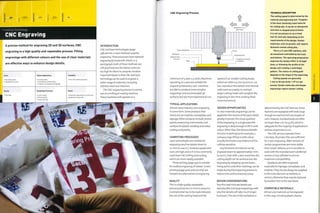
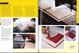
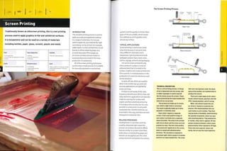
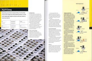
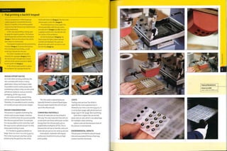
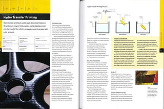
![Foil Blocking and Embossing Processes
Stage 2; Foil block Stage 2: Emboss
M
Foil blocking
film
Printing
foil
Stage 3: Unload Stage 3: Unload
The thickness depends on the density
and resilience of materials. Embossing is
generally limited to paper and card up to
2 mm (0.08 in.) or 500 gsm, plastic up to
i mm (0.04 in.) andleather. Any thickness
can be debossed (impressed on 1 side).
COSTS
Tooling costs are very low for both foil
blocking and embossing. Rotary tools and
matched tooling are more expensive.
Cycle time is rapid, and up to 1,000
parts per hour can be processed.
Labour costs in production are not
high, but changeover time is variable,
depending on the complexity of the
design because the tools have to be
registered with existing print.
ENVIRONMENTAL IMPACTS
Environmental impacts are very low.
Recycling used foil is impractical, so some
designs, such as borders, waste all of the
foil within the design area. Embossing
produces no waste.
TECHNICAL DESCRIPTION
Foil blocking and embossing are
essentially the same process. The
difference is that in foil blocking, a layer
of foil is placed between the tool and
substrate during stamping.
The tooling Is metal and Is
machined by laser cutting (page 2^81,
photochemical machining (page lUU] or
CNC engraving (page 396). The raised
areas of the tool apply the Image, and
can be used to apply either a positive or
negative Impression of the design.
In each process, heat and pressure are
applied. The metal tools are typically
100-200oC (212-392°F). They can be
linear or rotary In orientation; rotary
processes are very rapid and can be
used for continuous production of sheet
materials and cylindrical parts.
Metallic foils are very thin deposits of
aluminium, applied by vacuum metalizing
(page 372). Non-metallic colours, prints,
patterns and clear foils are thin films of
plastic. Both types are supported by a
plastic backing film. This also maintains
the Integrity of the film once the foil has
been printed. On the surface of the foil
is a thin film of adhesive that bonds the
delicate foil to the substrate.
The combination of heat and pressure
bond it to the substrate on contact. It
is embedded Into the surface, and the
depth of Impression is determined by
the hardness of the materials and the
pressure applied to the tool. The tool has
square edges, which help to provide a
clean edge on the cut out.
Embossing Is carried out between
matched tooling, whereas debossing only
requires an Impression tool. Emboss tools
have a small radius at the perimeter of
the design for aesthetic and functional
reasons; a sharp edge would stress the
fibre of the workplece. In a foil block-
emboss combination, the foil cut off Is not
as clean as in separate operations.
Case Study
^ Foil blocking paper
There are many different types of foij,
which are supplied on rolls (image 1). Rolls
are supplied 640 mm (25 in.) wide and
122,153 or 305 m (400,500 or 1,000 ft.)
long.The rolls are cut to length and
loaded onto the press (image 2). The
tooling is photochemically machined
magnesium (image 3). It is mounted onto
the press behind the foil. Each piece of
paper is picked up by a series of vacuum
nozzles, which feed it onto the impression
bed (image 4). The pressing takes less
than a second (image 5), and the paper
is unloaded.
After an impression, the foil (image 6)
is wound onto a take up reel. It is now
considered scrap. On the finished foil
blocking, the gold foil catches the light to
produce a shimmering and eye catching
design detail (image 7}.](https://image.slidesharecdn.com/manufacturingprocessesfordesignprofessionals-231008134532-9d8b1244/85/Manufacturing-Processes-for-Design-Professionals-pdf-209-320.jpg)
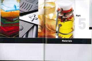
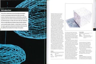
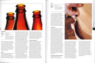
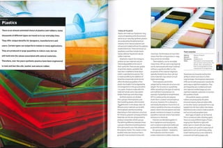
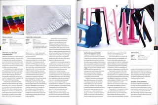
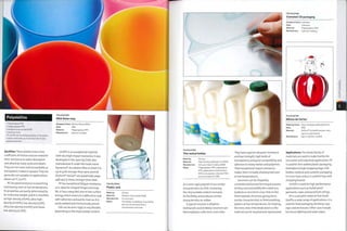
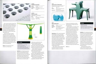
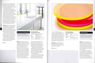
![THERMOPLASTIC POLYESTERS
Chevrolet HHR headlamp
Designer/client: DuPont™ Automotive/Chevrolet
Date: 2006
Material: Headlamp bezel and trim ring are
DuPont™ Crastin® polybutylene
terephthalate (PBT)
Manufacture: Injection moulded
Polyamides
• Polyamide (PA)
• Aromatic polyamide (Kevlar® and Nomex®)
PA. commonly known as nylon, is a versatile
material used in a wide range of applications.
Aromatic polyamides are stronger than steel for
their weight.
THERMOPLASTIC POLYESTERS
Flexometer® wrist guard
5^ Designer/client: Dr Marc-Herve Binet/Skimeter
'/] Date: 2003
Material: DuPont™ Hytrel® thermoplastic
polyester ITPC-ET)
Manufacture: Injection molding
its flexibility ranges from 30-80D. It has
high impact strength, tear strength and
impact resistance.
Applications: PET is used for drinks
bottles because it is transparent in its
amorphous state, is easily blow molded
and can withstand internal gas pressure
from carbonated drinks. Post-consumer
PET bottles are reprocessed into new
products such as textiles andfleeces.
PET is used as an industrial film. An
example is Madico's Lumisty view control
film. The textured surface on the film
refracts light and controls the viewing
angle either horizontally or vertically. It is
used as a coating on glass and plastic for
security, decoration, to reduce ultraviolet
light and to preverft glass disintegrating
if it breaks. It is a high performance
material: Northsails jDLandBDr
technology (page 228) laminates aramid
and carbon fibres between PET film.
PBT and PCT are used for oven handles
and knobs, electrical connector blocks,
switches and light bulb housing. LCP is
used for lighting connectors, computer
chip carriers, microwave oven parts
and cookware, mobile phone parts and
aerospace optical components.
TPC-ET is used in keypads, tubing,
seals, sports goods, medical devices and
soft touch handles.
Costs: Costs vary according to type: PET is
low to moderate cost, TPC-ET is moderate
cost, PBT and PCT are moderate to high
cost and LCP is high cost.
Qualities: There are many different
grades of nylon, which are categorized
as follows: nylon 6; nylon 6,6; nylon 6,12;
amorphous nylon (transparent) and high
temperature nylon.These grades can be
modified in a number of different ways
to produce reinforced,flame retardant,
tough and super-tough versions.
Nylon is self-lubricating,has alow
coefficient of friction, and has good
resistance to abrasion and chemicals.
There are 2 main types of aromatic
polyamides, including para-aramids
known by the DuPont™ trademark name
Kevlar®, and meta-aramids, which are
also known by the DuPont™ trademark
name Nomex®.They are only available
as spun fibre or sheet material because
there is no other practical way to form
them. They have superior resistance to
temperatures up to 5OO0C (9320F) and
are inherently flame retardant.
Para-aramidfibres have exceptional
strength to weight, far superior to steel.
Alongside UHDPE (see polyolefms,page
POLYAMIDES
Makita Impact Driver
Designer/client: Makita
Date: 2006
Material: Polyamide (PA) nylon body and
thermoplastic elastomer (TPE)
pistol grip
Manufacture: Multishot injection molded
430), they are as close as scientists have
come to mimicking spider web.
Meta-aramids are used mainly for
their high heat performance, electrical
insulation andflame resistance.They do
not have the same level of resistance to
cutting and abrasion as para-aramids
and so they are often reinforced or
.laminated into papers.
Applications: Nylon is used in bushes
and bearings, electrical equipment
housings,furniture parts (mechanisms
and feet) and sports equipment.
As a drawn fibre, it exhibits similar
properties to silk and so is widely used
as a substitute in garments, apparel and
carpets. Following its conception in the
1930s, nylon rapidly became a material in
its own right. Stockings and tights made
out of nylon are very successful because
they are dramatically cheaper than silk
versions. Cordura® is the trade name for
nylon fabrics from Invista; they are tough,
durable and resistant to abrasion.
Powdered nylon is fused into 3D forms
in rapid prototyping (page 232).
Para-aramids are used as a single
material for ropes and sheets, and
commonly as fibre reinforcement in
composite materials. Meta-aramids
are foun d in appl icati on s th at dem an d
very high performance such as power
generation, aircraft, aerospace, racing
cars and fire fighting. They are often
used as fabrics such as in flame resistant
undergarments worn by racing drivers.
Costs: Nylon is moderate cost and
aromatic polyamides are high cost.
ACETAL
Flo-Torq® IV propeller hub
Designer/client: Mercury Marine
Date: 2006
Material: DuPont™ Delrin® acetal
Manufacture: Over-molded by injection molding
onto titanium rods
Acetal
• Polyoxymethylene (POM)
POM, known as acetal, is an engineering polymer
that bridges the gap between plastics and
metals.
Qualities: A high level of crystallinity
means acetal is dimensionally stable
at peak temperatures and can operate
¦close to its melting point. It is resistant
to many chemicals, fuels and oils, and its
low coefficient of friction reduces wear.
It is tough, even at low temperatures,
with low warpage, and has high fatigue
endurance, so is suitable for spring and
snap fits. It is ideally suited to injection
molding (page 50) and machining (page
182), but can be rotation molded (page
36), blown (page 22) and extruded.
Applications: Acetal is used if the less
expensive thermoplastic polyester (page
437), PE (see polyolefins, page 430) and
polyamides (opposite) are not suitable. It
is important in the appliance, hardware
and automotive, industries where it has
replaced metal parts. Uses include
speaker grilles, sports goods, seatbelt
systems and automotive fuel systems.
Costs: Moderate to high.](https://image.slidesharecdn.com/manufacturingprocessesfordesignprofessionals-231008134532-9d8b1244/85/Manufacturing-Processes-for-Design-Professionals-pdf-221-320.jpg)
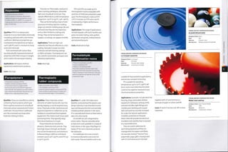
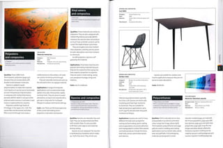
![POLYURETHANES
Open-cell foam balls
Made by: Various
Material: Foamed polyurethane resin (PUR]
Manufacture: Reaction injection molded
Notes: Most plastic can be foamed with
open or closed-cell structures.
PUR materials are resilient and
durable, and resistant to flexural fatigue,
abrasion and tearing.They operate at
temperatures up to i2o0C (2480F), but
tbey are affected by ultraviolet light
and will become hard and brittle with
prolonged exposure.
Applications: More than half of all PUR
is foamed.There are 3 main types: spray
foam, flexible foam and rigid foam.
Spray foam is used for filling holes, as
insulation or adhesive and to fill cavities
in products to make them more rigid.
Flexible foams are used to provide
cushioning in gym mats, carpet
underlining, most upholstered foam
furniture, other seating, mattresses,
car interiors, packaging, shoe soles and
linings in clothes and bags.
Rigid foam is used as an insulating
liner in fridges and freezers, in sports
and protective equipment and as a
core material in composite lamination
(page 206).
PUR is used for prototyping and low
volume production. Examples include
car bumpers, dashboards and interiors,
toys, sports equipment and housings for
consumer electronics.
PUR drawn fibre is resistant to cutting
and abrasion and is used in textiles, shoe
uppers and sports equipment.
As an adhesive and coating PUR is
used to protect and bond wood with
other materials. It is quick drying and
forms a watertight and rigid seal.
Costs: Low to moderate.
Silicones
• Silicone resins
These are low strength but highly versatile
materials. They are used as adhesives, gels,
rubbers and rigid plastics. They have excellent
electrical resistance and high heat stability, and
are chemically inert.
Qualities: This family of synthetic
polymers are derivedfrom the element
silicon (14 in the periodic table), but their
properties should not be confused.
Silicone resins are typically resistant
to water, chemicals and heat. They have
good insulating and lubricating
properties.These materials are non-toxic
SILICONES
Animal rubber bands
Designer/client: D-Bros/H Concept
Date: 2003
Material: Silicone
Manufacture: Extruded and cut
and have low levels of volatile organic
compounds (VOCs), which makes them
suitable for food preparation and
packaging and medical applications.
Silicones have a wide operating
temperature range from -no0C to
3i50C (-t66- 5990F).They are naturally
electrically insulating, but can be
modified with a carbon additive to make
them conductive.
They are shaped by injection molding
(page 50), compression molding (page
44), casting (page 40) and extrusion.
They are used by model makers because
certain grades cure at room temperature.
These are known as room temperature
vulcanizing (RTV) rubbers. They can
be coloured with a range of plain,
pearlescent, metallic, thermochromatic
and fluorescent pigments.
Applications: These are relatively
expensive materials, but their high
performance properties mean they
are suitable for a range of applications.
SILICONES
Skin Light
Designer; PD Design Studio
Date: 2006
Material: Silicone
Manufacture: Cast
Typical uses include O-rings, gaskets,
weather strips, seals, medical and
surgical equipment, and food processing
(for example, molds for chocolate).
Certain grades are considered safe
for children's toys, baby bottle teats
and medical implants. However, it is
uncertain whether silicone causes tissue
disease and so it is not recommended for
more than 25 days in the body.
As a liquid it is used as a lubricant and
release agent in RIM (page 64), composite
laminating (page 206) and compression
molding (page 44).
Costs: High cost.
SILICONES
Flexible ice cube tray
Designer/client: Unknown
Date: Unknown
Material: Silicone
Manufacture: Compression molded
Synthetic rubbers
»Isoprene rubber [IRl
• Chloroprene rubber ICR)
• Ethylene propylene rubbers [EPM and EPDM]
• Butyl rubber (lIRl
• Butadiene rubber IBRl
• Acrylonitrile butadiene rubber (ABRl
• Styrene butadiene rubber ISBR)
There are several different types of
synthetic rubber.They are used in place
of natural rubbers. They have shape
memory and so will return to their
original shape after deformation.
Qualities:They are resilient, resistant to
abrasion, have good low temperature
properties, good resistance to chemicals
and are typically electrically insulating.
IR is the synthetic version of natural
rubber (page 447) and consequently has
similar characteristics and applications.
CR was the first synthetic rubber,
invented by DuPont™ in the 1930s, and is
also known by their trademark name of
Neoprene®. it has very good resistance to
oils and atmospheric corrosion, making it
a suitable substitute for natural rubber.
EPM and EPDM have good resistance
to atmospheric corrosion and heat.They
range from 30A to 95A shore hardness.
IIR is impermeable to gas and
resistant to atmospheric corrosion. It
is utilized in tyre inner tubes.
SYNTHETIC RUBBERS
Divisuma 18 portable calculator
Designer/client: Mario Bellini/Olivetti SPA
Date,; 1973
Material; Synthetic rubber, acrylonitirile
butadiene styrene [ABS] and
melamine resin
Manufacture: Compression molding and
injection molding
ABRhas superior resistance to oil and
fuel, and SBR is the cheapest and most
common form of synthetic rubber.
SBR is a widely used low cost rubber
with properties similarto natural rubber.
Applications: Synthetic rubbers are used
in place of natural rubbers in a range of
applications.Typical products include
fuel hoses, gaskets, washers, O-rings,
diaphragms, tank linings and seals.
Neoprene® is well known for use in
wetsuits, footwear and other sportswear.
Costs: Low to high cost.
O
CO](https://image.slidesharecdn.com/manufacturingprocessesfordesignprofessionals-231008134532-9d8b1244/85/Manufacturing-Processes-for-Design-Professionals-pdf-224-320.jpg)
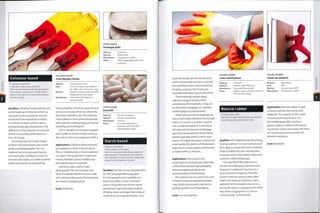
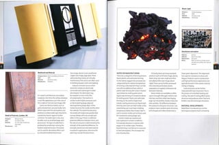
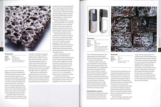
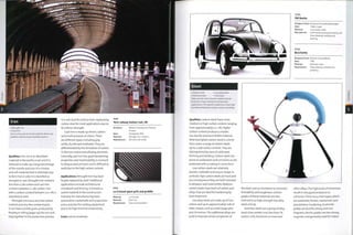
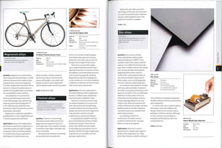
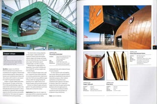
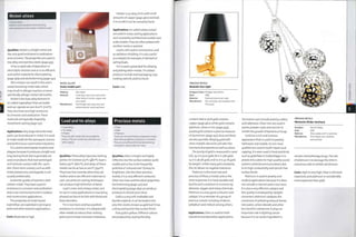
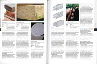
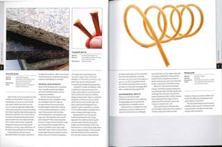
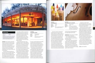
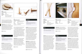
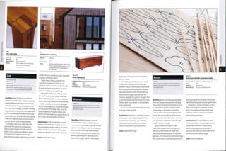
![Fruitwood
Iroko
• Cherry
• Apple
• Pear
This range of deciduous hardwood fruiting
trees are used for their decorative appearance
combined with moderate strength. Cherry is the
most well known.
• Iroko
Iroko is an African hardwood that is naturally
resistant to chemicals and decay. It has similar
properties to teak and so is often-used as a
cheaper alternative.
FRUITWOOD
Bread board
Made by: Unknown •
Material: cherry
Manufacture: Hand carved
Notes: Cherry is a hard, dense and
decorative wood.
Apple (Malus species) is a slow
growing and not very tall tree. This
means that it is difficult to obtain large
planks of it. The timber has a tightly
packed grain and is heavy and hard. Like
other fruitwoods, apple shrinks a great
deal as it is dried, and this can cause
warping and cracking.
Pear trees (Pyrus species) are similar
to apple trees.- they are slow growing and
not very tall. The timber varies from light
pinkish brown to yellowish brown. It has
a tight grain and smooth, hard surface.
Applications: These woods are available
as sawn timber and veneer. They are used
for turning, machining (page 782) and as
decorative veneers. Cherry is used in
furniture, cabinets, floors and doors,
Apple and pear are used for ornaments,
tableware, wooden instruments and
furniture. They have fragrant smoke, so
are used to flavour food and tobacco.
Costs: High,
Designer:
Date:
Material:
Manufacture:
Retrouvius
Completed 2006
Reclaimed iroko
Machining
Applications: Sawn timber and veneer
are used for flooring, decking, outdoor
furniture, worktops and general joinery.
It has been used in laboratories due to its
resistance to chemicals and water decay.
Costs: Moderate.
IROKO
Iroko work surface
Qualities: Cherry {Prums species) has
distinctive and desirable heartwood
of a rich reddish brown colour that
gradually darkens with age. Sometimes
it is speckled with darker patches. It is
moderately slow growing and reaches
heights of 30 m (98 ft) or so. There
are many different species including
American cherry (black cherry), wild
cherry and Brazilian cherry. Once dried it
15 Stab,e' moderately dense and strong.'
It has a straight and uniform grain that
can be polished to a high finish. The
heartwood is resistant to decay. However,
it is a high cost timber and so is often
us6d as a. veneer.
Qualities: Iroko [Chlorophora species) is
an African hardwood. It is endangered
and protected in some countries, but
there is sufficient production from other
sources for it to be competitively priced.
It has light yellow sapwood and brown
heartwood. It is used for decorative
appeal as well as durability and strength.
Iroko contains natural oils that protect
it from water decay and chemicals
Outdoors it gradually turns silvery grey
Its interlocking grain produces good
mechanical properties, but can cause
tearing during machining (page 182).
Hard calcium carbonate deposits in the
wood fibres can blunt cutting tools.
Exotic hardwoods
• Mahogany . Teak
•Ziricote -Ebony
• Keruing . Weng.
• Rosewood
This is a group of highly decorative timbers with
lustrous colours. Certain species are very hard
and durable. Some are endangered.
Qualities: These woods are highly priced
and hard to come by, due to their places
of origin, desirability and rate of growth
They are prized for their lustrous colours;
ebony [Diospyros ebenum) is black or very
dark red, ziricote [Cordia dodecandm) has
a deep, contrasting swirling grain, wenge
(Millettia laurentii] is a dark chocolate,
EXOTIC HARDWOODS
Reclaimed teak stool
Designer: Mandala
Date: 2006
Material: Reclaimed teak
Manufacture: Hand carved
rosewood {Dalbergia species) is a veined
brown and mahogany (Khaya species) is
a rich brown that darkens with age.
These materials, especially ebony and
wenge, are very hard and resistant to
denting.Teak (Tectona species), keruing
[Dipterocarpus species) and mahogany
contain natural oils that protect them
against decay, so are popularfor outdoor
furniture, decking and boat building.
Care must be taken when specifying
or purchasing exotic hardwoods. Certain
endangered species (such as Swietenia,
the original mahogany) are protected by
international legislation, and permits are
requi re d for tradi n g.
Applications: Limited availability as
sawn timber and veneers. They are used
in flooring,furniture, ornaments,musical
instruments and for decorative inlay.
Costs: High to very high.
EXOTIC HARDWOODS
Bluetooth ziricote Pip*Phone
Designer/client: Nicolas Roope and Kam Young/
Hulger
Date: 2005
Material: Ziricote
Manufacture: CNC machined](https://image.slidesharecdn.com/manufacturingprocessesfordesignprofessionals-231008134532-9d8b1244/85/Manufacturing-Processes-for-Design-Professionals-pdf-241-320.jpg)
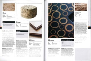
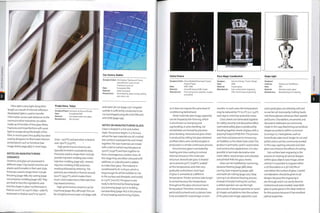
![Glass mirrors are produced by coating
glass with a fine layer of silver, followed
by copper (or other metal) and a
protective 1 acquer. Twin-walled bl own
glass (see image, page 485,right) can be
silvered on the inside and sealed without
the need for a protective layer. Protecting
or sealing is essential because otherwise
silver will tarnish and corrode.The blown
glass technique has both decorative and
functional uses. Silver prevents radiation
of heat, a quality used in the production
of glass vacuum (thermos) flasks.
Tempered glass, also known as safety
or toughened glass, is produced by heat
treatment. Soda-lime glass is heated to
Litracon® light transmitting concrete
Made by: Litracon Bt, Hungary
Material: Glass fibres (4%) in a fine
concrete matrix
Manufacture: Cast
approximately 6500C (i2O20F) and then
quenched in blasts of cool air. This forces
the surface of the glass to cool more
rapidly than the core andthus forms a
structure under compression. As a result,
tempered glass is several times stronger
than annealed glass. However, once
tempered, it cannot be modified or
jsql* VvA
Sponge and sponge vase
Designer/
made by:
Date:
Material:
Manufacture:
Marcel Wanders/Moooi
1997
Porcelain
To make this form a natural
sponge (top) is dipped in liquid
ceramic slip and fired (above).
machined. When it breaks, the fragments
tend to be small and blunt as a result of
the modified structure, so it is used in
safety applications such as door glazing,
car windscreens anddinnerware.
High performance glass is made at
el evated tem peratures an d so i s m ore
difficult and expensive to fabricate.
MATERIAL DEVELOPMENTS
Developments in ceramics and glass
have been concentrated in the high
performance materials and coatings.
Materials are being combined in
different ways to produce new composite
materials such as light transmitting
concrete and lightweight foamed panels.
Litracon® (see image, above left) is
a light transmitting concrete invented
by Hungarian architect Aron Losonczi
in 2001. It is made up of glass fibres
embedded in a fine concrete matrix.The
glass fibres are in parallel alignment and
so transmit light through the concrete
without distorting the image.The fibres
Aerogel and Peter Tsou, JPL scientist
Made by: JPL (Jet Propulsion Laboratory]
Material: Aerogel (NASA/JPL)
Manufacture: N/a
Notes: Silica with a porous, dendritic-
like structure
are very thin and make up approximately
4% of the material, so they do not affect
its structural integrity.
Ceramic and glass foams harness the
high temperature properties of these
materials in the form of lightweight
structural materials. Ceramic foams are
typically formed by saturating polymer
fo^m (or similar porous material) with
ceramic slurry.The firing process hardens
the ceramic and simultaneously burns
out the foam. A range of ceramics can
be formed in this way.Two applications
include high temperature filtration and
thermal insulation. In a project for Droog
Design and Rosenthal, Marcel Wanders
developed a similar technique for the
production of domestic ceramics (see
images, opposite).
Glass foams are formed by adding a
foaming agent to the raw material.
Bubbles form in the molten glass and are
locked in place as it cools. Each bubble is
sealed into the glass (closed cell), so it
remains watertight and gastight. Foams
can be formed from crushed (recycled)
glass by mixing the ingredients in a
mold. As the crushed glass is heated the
gassing agent produces bubbles that are
encapsulated in the molten structure.
Ceramic fibres and textiles can
withstand temperatures up to 14500C
(2642°F).The material determines the
temperature resistance. They are used for
insulation (as mineral wool),fire
protection and other high temperature
applications. Products include textiles,
non-wovens,foil and rope.
Aerogel (see image) is made up of
an open cell silica structure. It is very
low density and can be as much as
gg.8% atmosphere, so it is extremely
lightweight. Like ordinary glass, it is
fragile and brittle, but it is a much more
efficient insulator because the internal
structure has avast surface area. It
is considerably more expensive than
ordinary glass and is not yet available
in transparent grades.There are not
many commercial applications outside
aerospace. However, in 2007 Dunlop
Sports released a range of tennis
rackets with an aerogel core. Its extreme
lightness is used to produce a racket with
high strength to weight and stiffness.
Avast range of coatings have been
developed to improve the characteristics
of glass. These include dichroic, anti-
reflective, thermally insulating, sound
reflecting, self-cleaning and view control.
Pilkington developed self-cleaning
glass in 2001. Pilkington Activ™ is
produced by coating flat glass with a very
thin, transparent layer of titanium oxide.
This produces a surface that is both
hydrophilic and photocatalytic. In
combination, these qualities help to
maintain a surface that is free of dirt and
watermarks: UV radiation helps to break
down surface dirt, which is subsequently
washed away by rain.
ENVIRONMENTAL IMPACTS
Glass production is a hot and energy
intensive process. Gullet mixed with the
raw ingredients reduces the amount
of energy required in production. Glass
can be recycled indefinitely without any
degradation to its structure. However,
the use of cull et may have an impact
on the colour of the glass. Clear glass
cannot tolerate impurities and colour
contamination, whereas brown and](https://image.slidesharecdn.com/manufacturingprocessesfordesignprofessionals-231008134532-9d8b1244/85/Manufacturing-Processes-for-Design-Professionals-pdf-245-320.jpg)
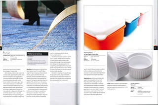
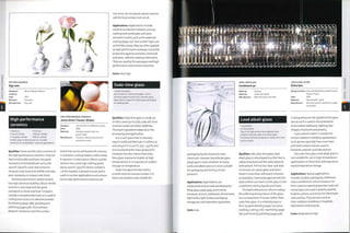
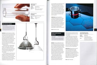
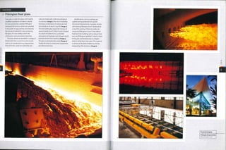
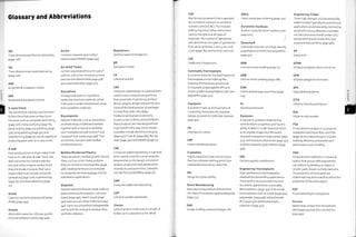
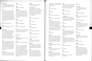
![POM
Polyoxymethylene.
PP
Polypropylene.
PS
Polystyrene.
PSL
Parallel strand lumber.
PTFE
Polytetrafl uoro ethyl en e.
PU
Polyurethane [thermoplastic, almost
exclusively injection molding].
PUR
Polyurethane resin [thermosetting, resin,
ie most occurences],
PVA
Polyvinyl acetate.
PVC
Polyvinyl chloride.
PVOH
Polyvinyl alcohol.
PW
Plasma welding (page 282).
RAL
Reichsausschuss fiir Lieferbedingungen
is a German colour chart system used
mainly in paint and pigment colour
specification.
Rays
Vessels radiating from the centre of a
tree's stem andbranchesfortransporting
food and waste laterally.They are
responsible for the characteristic flecks of
colour in hardwoods (page 472) such as
beech and oak.
Resin
A natural or synthetic, semi-solid or solid
substance, produced by polymerization
or extraction from plants, and used in
plastics, varnishes and paints.
RF
Radio frequency.
RFW
Rotary friction welding (page 294).
RIM
Reaction injection molding (page 64).
RRIM
Reinforced reaction injection molding.
RTM
Resin transfer molding.
RTV
Room temperature vulcanizing,
occurs when certain rubbers, such as
silicone, are chemically cured at room
temperature, as opposed to heat curing.
SAN
Styrene acrylonitrile.
Sapwood
Young and light-coloured wood that
forms between the bark and heartwood
(page 471) of a tree.
SAW
Submerged arc welding (page 282).
SBR
Styrene butadiene rubber.
SBS
Styrene butadiene styrene.
Seasoned Timber
Traditionally used to describe air-dried
timber with a moisture content of less
than 20%. Compared to green timber
(page 467), dried timber has improved
dimensional stability,toughness,
bending stiffness, impact resistance,
electrical resistance, resistance to
decay and adhesive bond strength. The
required level of moisture depends on
the application (see also air-dried timber,
page 496, and kiln-dried timber, page
498).
SEBS
Styrene ethylene butylene styrene.
Semi-crystalline
A molecular structure that contains both
crystalline (page 425) and amorphous
(page 425) patterns: for example,
polyethylene terephthalate (PET) (see
thermoplastic polyesters, page 437).
Shape Memory
The ability of a material to be heavily
manipulated andthen return to its
original shape, sometimes with the
application of heat. Materials with shape
memory include synthetic rubbers (page
445) and certain metal alloys (page 452).
Shore Hardness
Thehardness of aplastic, rubber or
elastomer is measured by the depth of
indentation by a shaped metal foot on
a measuring instrument known as a
urometer. The depth of indentation is
measured on a scale of o to 100; higher
numbers indicate harder materials.
These tests are generally used to
denote the flexibility of a material. The
2 most popular are Shore A and Shore D.
Indenterfeet with different profiles are
used in each case, and so each method is
suitable for different material harnesses.
For example, soft materials are measured
on the Shore A scale, and hard materials
are measured on the Shore D scale.There
is not a strong correlation between
different scales. Shore hardness is also
known as durometer hardness.
SLA
Stereolithography (page 232).
SLS
Selective laser sintering (page 232).
SMC
Sheet molding compound (page 218).
Softwood
Wood from coniferous and typical
evergreen trees, such as cedar,fir, pine
and spruce (see softwoods, page 470).
SRIM
Structural reaction injection molding.
Sub-surface Laser Engraving
The process of laser-marking clear
materials below the surface: 2D and 3D
designs are reproduced as point clouds,
which are sets of closely packed laser
markings that outline the shape. Sub¬
surface laser engraving is also known as
vitrography.
Tampo Printing
Another name for pad printing (page
404).
Teflon®
DuPont™ trade name for
polytetrafluoroethylene (PTFE) and
ethylene tetrafluoroethylene (ETFE) (see
fluropolymers, page 440).
Terpolymer
A polymer made up of long chains
of 3 repeating monomers, such as
acrylonitirile butadiene styrene (ABS)
(see styrenes, page 432).
Thermochromatic
A compound that changes colour
as its temperature goes up or down.
Thermochromatic pigments are available
for inks, plastics and coatings.
Thermoplastic
A polymer that becomes soft and pliable
when heated. In its plastic state it can
be shaped and re-shaped by a range
of molding processes, such as blow
molding (page 22) and injection molding
(page 50). Examples include polyamide
(PA) nylon (page 438), polycarbonate
(PC) (page 428) and polypropylene (PP)
(see polyolefins, page 430) (see also
commodity thermoplastic, page 497, and
engineering thermoplastic, page 497).
Thermoplastic Elastomer
A general name used to describe
thermoplastic materials that exhibit
similar elastic properties to rubber.
Thermosetting Plastic
A material formed by heating,
catalyzing or mixing 2 parts to trigger a
i-way polymeric reaction. Unlike most
thermoplastics, therm osetting pi astics
form cross-links between the polymer
chains, which cannot be undone, and
so this material cannot be reshaped or
remolded once cured. Thermosetting
plastics tend to have superior resistance
to fatigue and chemical attack than
thermoplastic (page 435).
TIG
Tungsten inert gas.
TPC-ET
Thermoplastic polyester elastomer.
TPE
Thermoplastic elastomer.
TPU
Thermoplastic polyurethane.
UF
Urea form aldehyde.
UHDPE
Ultra high-density polyethylene.
ULDPE
Ultra low-density polyethylene.
uPVC
Unplasticized polyvinyl chloride.
UV
Ultraviolet.
Verdigris
Another name for the green patina that
forms on the surface of copper (page
460). It comes from the French vert de
Grice.
Vulcanize
The process of curing natural rubber
with sulphur, heat and pressure in a
i-way reaction to form a thermosetting
material (see thermoset, page 445).
Xylem
The fibrous material that makes up the
stem and branches of trees and shrubs. It
consists mostly of a series of elongated,
rigid walled cells and provides trees and
shrubs with an upward flow of water and
mechanical support (see also heartwood,
page 498, and sapwood, page 500).](https://image.slidesharecdn.com/manufacturingprocessesfordesignprofessionals-231008134532-9d8b1244/85/Manufacturing-Processes-for-Design-Professionals-pdf-252-320.jpg)