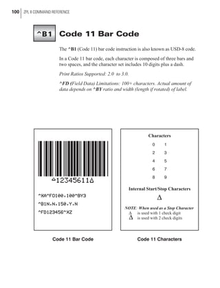
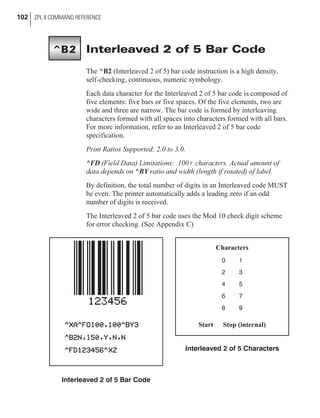
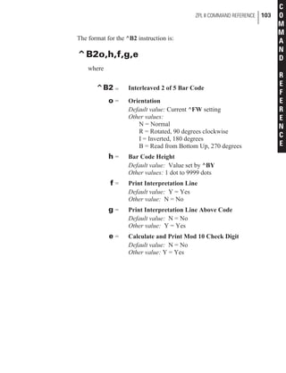
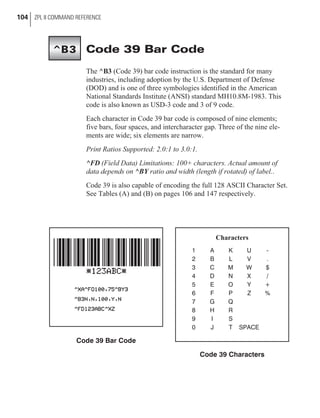
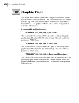
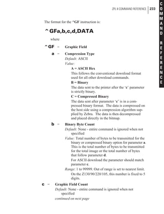
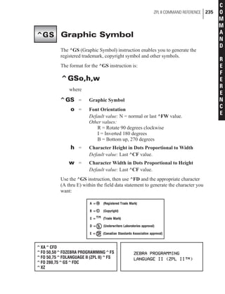
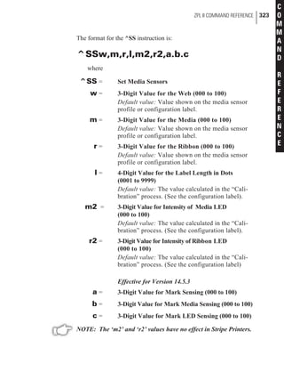
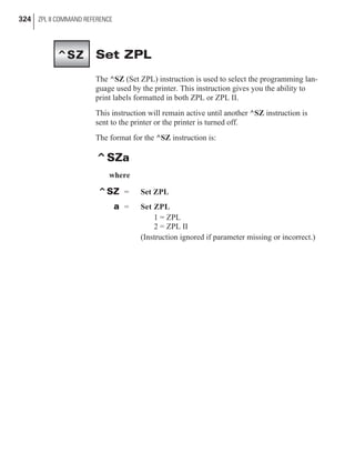
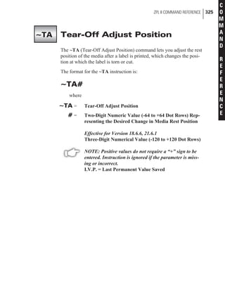
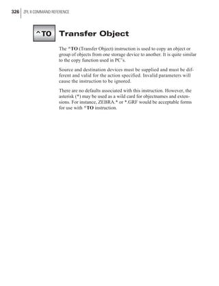
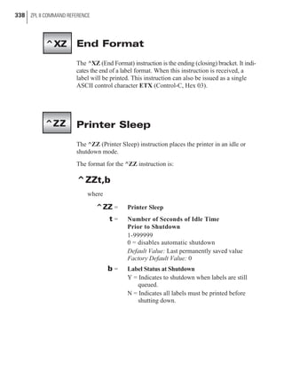
This document is a programming guide for Zebra label printers that provides instructions on how to use Zebra Programming Language II (ZPL II). It includes chapters that cover ZPL II basics, printer configuration, programming exercises, and advanced techniques. The guide also includes a command reference, appendices with charts and protocols, and covers topics like fonts, barcodes, graphics, stored formats, and printer networking.


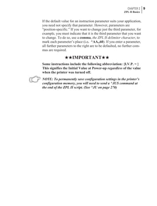
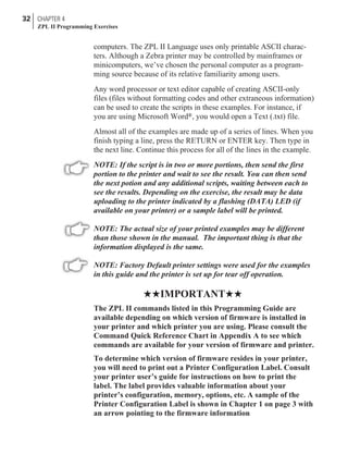
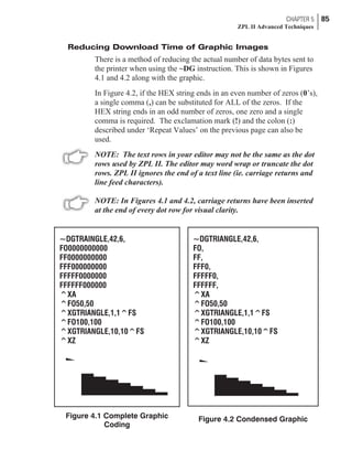
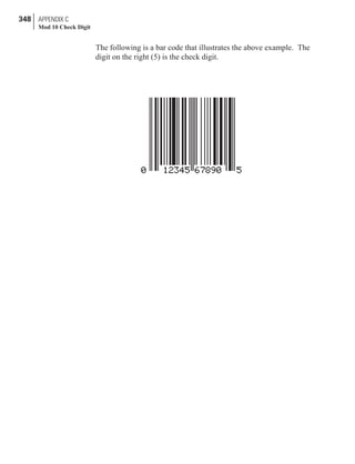
![An Example of a Basic Label
This exercise is designed to guide you through the basic steps to cre-
ate a common label which contains text and a bar code.
Refer to Chapter 4, Introduction, for more information on how to set
up your printer and how to enter ASCII text to send to your printer.
Type the programming instructions (shown in bold) in the order
given. An explanation of what each instruction does is in brackets [ ].
A printed example of the label is on the next page with arrows point-
ing to the different parts that make up the label and an indication of
the ZPL II command that was used to create it.
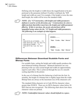
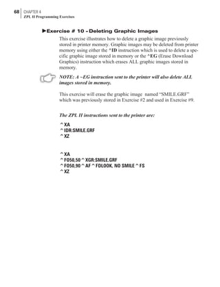
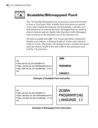
^XA
[^XA - Indicates start of label format.]
^LH30,30
[^LH - Sets label home position 30 dots to the right and
30 dots down from top edge of label.]
^FO20,10^AD^FDZEBRA^FS
[^FO20,10 - Set field origin 20 dots to the right and 10 dots
down from the home position defined by the
^LH instruction.]
[^AD - Select font “D.”]
[^FD - Start of field data.]
[ZEBRA - Actual field data.]
[^FS - End of field data.]
^FO20,60^B3^FDAAA001^FS
[^FO20,60 - Set field origin 20 dots to the right and 60 dots
down from the home position defined by the
^LH instruction.]
[^B3 - Select Code 39 bar code.]
[^FD - Start of field data for the bar code.]
[AAA001 - Actual field data.]
[^FS - End of field data.]
^XZ
[^XZ - Indicates end of label format.]
10 CHAPTER 2
ZPL II Basics](https://image.slidesharecdn.com/manuallenguajezebra-150520210931-lva1-app6892/85/Manual-lenguaje-zebra-19-320.jpg)
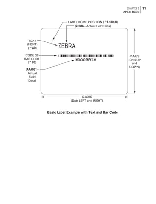
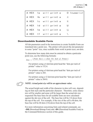
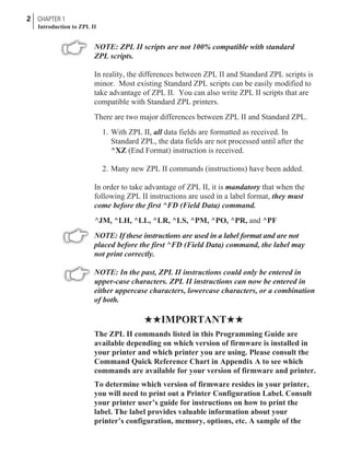
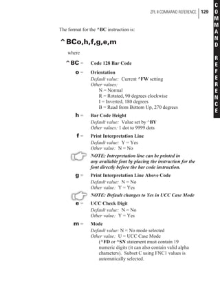
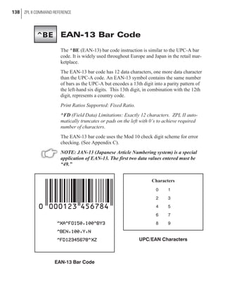
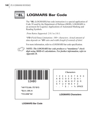
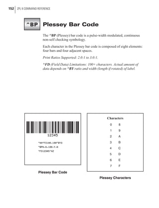
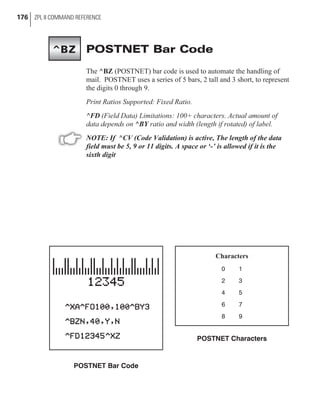
![Bar Code Field Instructions
To create a bar code, a bar code field instruction must be contained in
the label format. Table 2 shows all of the bar code field instructions.
The number in brackets denotes the print ratio. Each instruction pro-
duces a unique bar code.
CHAPTER 2 17
ZPL II Basics
^B1 Code 11 (USD-8) [ 2.0 - 3.0 ]
^B2 Interleaved 2 of 5 [ 2.0 - 3.0 ]
^B3 Code 39 (USD-3 & 3 of 9) [ 2.0 - 3.0 ]
^B4 Code 49 (*) [ Fixed ]
^B7 PDF417 (*) [ Fixed ]
^B8 EAN-8 (*) [ Fixed ]
^B9 UPC-E (*) [ Fixed ]
^BA Code 93 (USS-93) (*) [ Fixed ]
^BB CODABLOCK A, E, F (*) [ Fixed ]
^BC Code 128 (USD-6) (*) [ Fixed ]
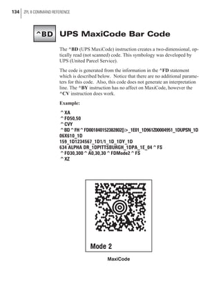
^BD UPS MaxiCode [ Fixed ]
^BE EAN-13 (*) [ Fixed ]
^BF Micro-PDF417 [ Fixed ]
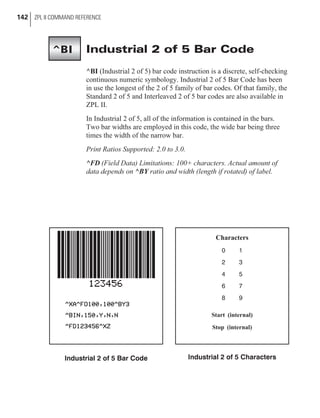
^BI Industrial 2 of 5 [ 2.0 - 3.0 ]
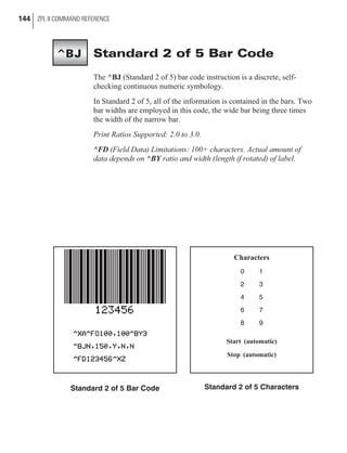
^BJ Standard 2 of 5 [ 2.0 - 3.0 ]
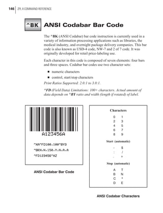
^BK ANSI Codabar (USD-4 & 2 of 7) [ 2.0 - 3.0 ]
^BL LOGMARS [ 2.0 - 3.0 ]
^BM MSI [ 2.0 - 3.0 ]
^BP Plessey [ 2.0 - 3.0 ]
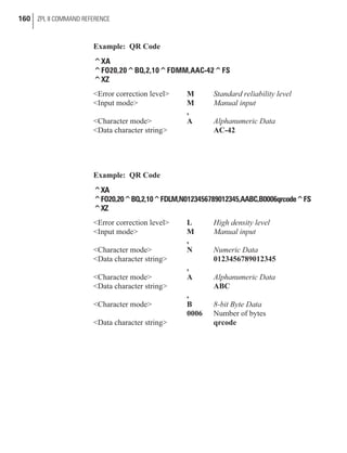
^BQ QR Code [ Fixed ]
^BS UPC/EAN Extensions (*) [ Fixed ]
^BU UPC-A (*) [ Fixed ]
^BX Data Matrix [ Fixed ]
^BZ PostNet (*) [ Fixed ]
(*) Fixed Printing Ratio - This means that the ratio between the width of the
bars in the code is a fixed standard and cannot be changed.
Table 2. Available Bar Codes](https://image.slidesharecdn.com/manuallenguajezebra-150520210931-lva1-app6892/85/Manual-lenguaje-zebra-26-320.jpg)

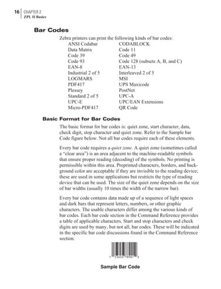
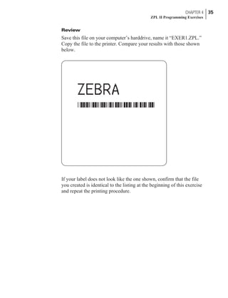
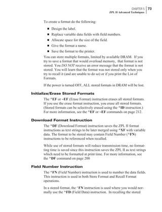
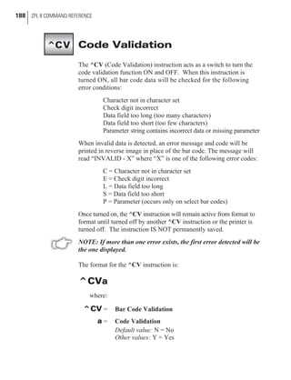
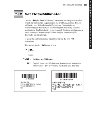
![Programming Instructions
Type the instructions (shown in bold) in the order given. An explana-
tion of what each instruction does is in brackets ( [ ] ).
^XA
[^XA - Indicates start of label format.]
^LH30,30
[^LH - Sets label home position 30 dots to right and 30 dots
down from top edge of label.]
^FO20,10^AFN,56,30^FDZEBRA^FS
[^FO - Set field origin relative to label home.]
[^AF - Select font “F” and sets character size to 56 dots high
and 30 dots wide]
[^FD - Start of field data.]
[ZEBRA- Actual field data.]
[^FS - End of field data.]
^FO20,80,^B3N,Y,20,N,N^FDAAA001^FS
[^FO - Set field origin relative to label home.]
[^B3N,Y,20,N,N - Select Code 39 bar code. Calculate
check digit, do not print interpretation line.]
[^FD - Start of field data for bar code.]
[AAA001 - Actual field data.]
[^FS - End of field data.]
^ISR:EXERPROG.GRF,N
[^IS - Save format as a graphic image named
“EXERPROG.GRF,” do not print after saving.]
^XZ
[^XZ - Indicates end of label format.]
(Data is uploaded to printer RAM.)
^XA^ILR:EXERPROG.GRF,N^XZ
[^XA - Start of label format.]
[^ILR:EXERPROG.GRF,N - Load and print the graphic
image saved as “EXERPROG.GRF”]
[^XZ - End of label format.]
34 CHAPTER 4
ZPL II Programming Exercises](https://image.slidesharecdn.com/manuallenguajezebra-150520210931-lva1-app6892/85/Manual-lenguaje-zebra-43-320.jpg)
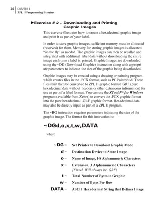
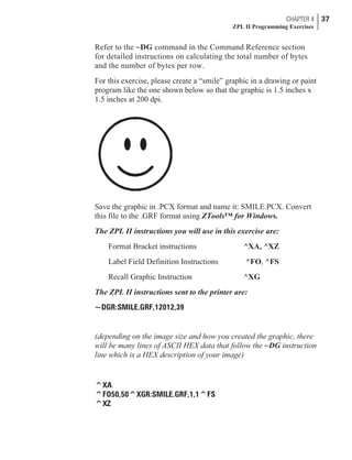
![Programming Instructions
Type the instructions (shown in bold) in the order given. An explana-
tion of what each instruction does is in brackets ( [ ] ).
~DGR:SMILE.GRF,12012,39
[^DG - Download graphic named “SMILE,” which has
12012 total bytes with 39 bytes per row]
(depending on the image size and how you created the graphic, there
will be many lines of ASCII HEX data that follow the ~DG instruction
line which is a HEX description of your image)
^XA
[^XA - Indicates start of label format.]
^FO50,50^XGR:SMILE.GRF,1,1^FS
[^FO - Set field origin relative to label home.]
[^XG - Recall graphic named “SMILE” from memory
with a magnification of 1:1 along X and Y axis.]
[^FS - End of field data.]
^XZ
[^XZ - Indicates end of label format.]
38 CHAPTER 4
ZPL II Programming Exercises](https://image.slidesharecdn.com/manuallenguajezebra-150520210931-lva1-app6892/85/Manual-lenguaje-zebra-47-320.jpg)
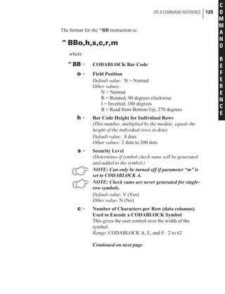
![Programming Instructions
Type the instructions (shown in bold) in the order given. An explana-
tion of what each instruction does is in brackets.
^XA^PRB^XZ
[^XA - Indicates start of label format.]
[^PRB - Set print rate to speed “B.” (3 inches/second)]
[^XZ - End of ZPL program.]
^XA
[^XA - Indicates start of label format.]
^LH360,30
[^LH - Sets label home position 360 dots to right and 30 dots
down from top edge of label.]
^FO20,10^AF^FDZEBRA^FS
[^FO - Set field origin relative to label home.]
[^AF - Select font “F”
[^FD - Start of field data.]
[ZEBRA- Actual field data.]
[^FS - End of field data.]
^FO20,20,^B3^FDAAA001^FS
[^FO - Set field origin relative to label home.]
[^B3 - Select Code 39 bar code.]
[^FD - Start of field data for bar code.]
[AAA001 - Actual field data.]
[^FS - End of field data.]
^POI
[^POI - Set print orientation to Invert the entire label.]
^PQ2
[^PQ2 - Set print quantity to print 2 labels.]
^XB
[^XB - Suppress Backfeed for tear-off modes.]
Instructions continued on next page.
CHAPTER 4 41
ZPL II Programming Exercises](https://image.slidesharecdn.com/manuallenguajezebra-150520210931-lva1-app6892/85/Manual-lenguaje-zebra-50-320.jpg)
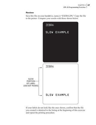
![^XZ
[^XZ - Indicates end of label format.]
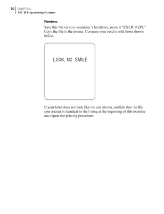
Review
Save this fileon your harddrive, name it “EXER3.ZPL” Copy the file
to the printer. Compare your results with those shown below.
If your labels do not look like the ones shown, confirm that the file
you created is identical to the listing at the beginning of this exercise
and repeat the printing procedure.
42 CHAPTER 4
ZPL II Programming Exercises](https://image.slidesharecdn.com/manuallenguajezebra-150520210931-lva1-app6892/85/Manual-lenguaje-zebra-51-320.jpg)
![Programming Instructions
Type the instructions (shown in bold) in the order given. An explana-
tion of what each instruction does is in brackets.
^XA
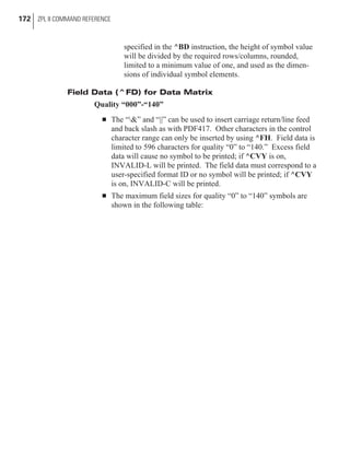
[^XA - Indicates start of label format.]
^PR2
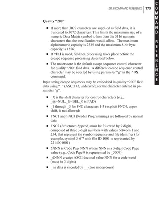
[^PR2 - Set print rate to speed of 2 inches/second]
^LRY
[^LRY - Reverse print entire label.]
^LH30,30
[^LH - Sets label home position 30 dots to right and 30
dots down from top edge of label.]
^FO0,0^GB400,300,300^FS
[^FO - Set field origin relative to label home.]
[^GB - Create a filled graphic box to be used as
background for reverse printed label. (May need
to adjust parameters for different media size.]
^FO20,10^AF^FDZEBRA^FS
[^FO - Set field origin relative to label home. ]
[^AF - Select font “F.”]
[^FD - Start of field data.]
[ZEBRA- Actual field data.]
[^FS - End of field data.]
^FO20,60^B3,,40^FDAAA001^FS
[^FO - Set field origin relative to label home.]
[^B3 - Select Code 39 bar code.]
[^FD - Start of field data for bar code.]
[AAA001 - Actual field data.]
[^FS - End of field data.]
^PF50
[Slew 50 dot rows at bottom of label.]
44 CHAPTER 4
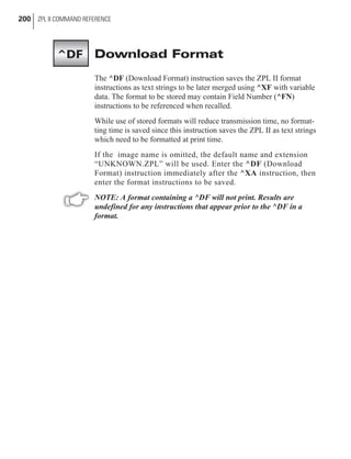
ZPL II Programming Exercises](https://image.slidesharecdn.com/manuallenguajezebra-150520210931-lva1-app6892/85/Manual-lenguaje-zebra-53-320.jpg)
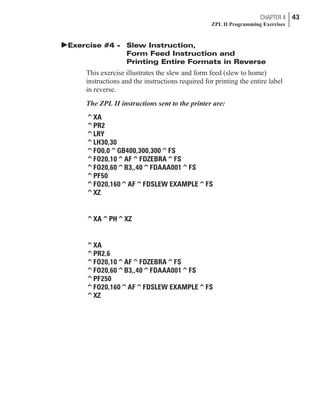
![^FO20,160^AF^FDSLEW EXAMPLE^FS
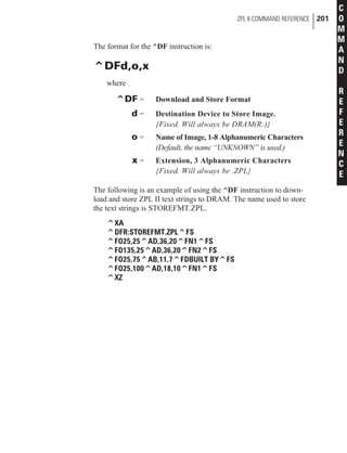
[^FO - Set field origin relative to label home. ]
[^AF - Select font “F.”]
[^FD - Start of field data.]
[SLEW EXAMPLE - Actual field data.]
[^FS - End of field data.]
^XZ
[^XZ - Indicates end of format.]
^XA^PH^XZ
[Instructions to feed to next home position.]
^XA
[^XA - Indicates start of format.]
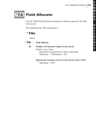
^PR2,6
[^PR2 - Set print rate to speed of 2 inches/second, set slew
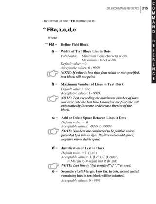
rate to speed of 6 inches/second]
^FO20,10^AF^FDZEBRA^FS
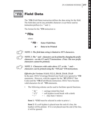
[^FO - Set field origin relative to label home. ]
[^AF - Select font “F.”]
[^FD - Start of field data.]
[ZEBRA- Actual field data.]
[^FS - End of field data.]
^FO20,60^B3,,40^FDAAA001^FS
[^FO - Set field origin relative to label home.]
[^B3 - Select Code 39 bar code.]
[^FD - Start of field data for bar code.]
[AAA001 - Actual field data.]
[^FS - End of field data.]
^PF250
[^PF250 - Slew 250 dot rows.]
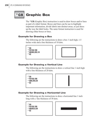
Instructions continued on next page.
CHAPTER 4 45
ZPL II Programming Exercises](https://image.slidesharecdn.com/manuallenguajezebra-150520210931-lva1-app6892/85/Manual-lenguaje-zebra-54-320.jpg)
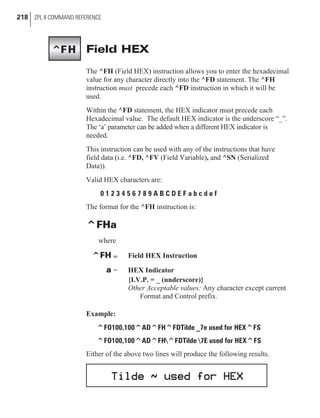
![^FO20,160^AF^FDSLEW EXAMPLE^FS
[^FO - Set field origin relative to label home. ]
[^AF - Select font “F.”]
[^FD - Start of field data.]
[SLEW EXAMPLE - Actual field data.]
[^FS - End of field data.]
^XZ
[^XZ - Indicates end of format.]
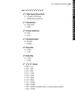
46 CHAPTER 4
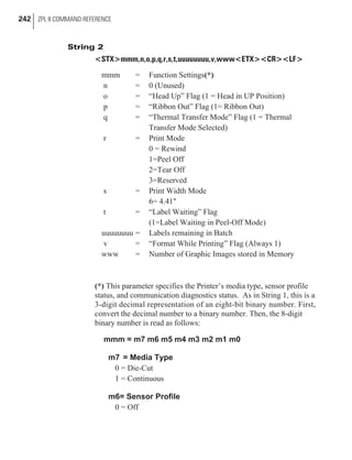
ZPL II Programming Exercises](https://image.slidesharecdn.com/manuallenguajezebra-150520210931-lva1-app6892/85/Manual-lenguaje-zebra-55-320.jpg)
![Programming Instructions
Type the instructions (shown in bold) in the order given. An explana-
tion of what each instruction does is in brackets.
^XA
[^XA - Indicates start of label format.]
^LH30,30
[^LH - Sets label home position 30 dots to right and 30
dots down from top edge of label.]
^FO20,10^AF^FDZEBRA^FS
[^FO - Set field origin relative to label home. ]
[^AF - Select font “F.”]
[^FD - Start of field data.]
[ZEBRA- Actual field data.]
[^FS - End of field data.]
^FO20,60^B3,,40,,^FDAA001^FS
[^FO - Set field origin relative to label home.]
[^B3 - Select Code 39 bar code.]
[^FD - Start of field data for bar code.]
[AA001 - Actual field data.]
[^FS - End of field data.]
^FO20,180^AF^SNSERIAL NUMBER 00000000111,1,Y^FS
[^FO - Set field origin relative to label home. ]
[^AF^SNSERIAL NUMBER 00000000111,1,Y- Define
serialized field, starting value of 111, increment
by 1, insert leading zeros.]
[^FS - End of field data.]
^PQ10
[^PQ10 - Set print quantity to 10.]
^XZ
[^XZ- Indicates end of format.]
CHAPTER 4 49
ZPL II Programming Exercises](https://image.slidesharecdn.com/manuallenguajezebra-150520210931-lva1-app6892/85/Manual-lenguaje-zebra-58-320.jpg)
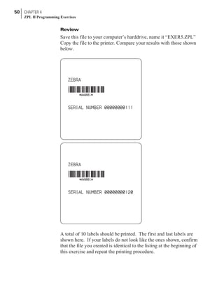
![Programming Instructions
Type the instructions (shown in bold) in the order given. An explana-
tion of what each instruction does is in brackets.
^XA
[^XA - Indicates start of label format.]
^DFFORMAT^FS
[^DF - Download and store format.]
[FORMAT - Name of format.]
[^FS - End of field data.]
^LH30,30
[^LH - Sets label home position 30 dots to right and 30
dots down from top edge of label.]
^FO20,10^AF^FN1^FS
[^FO - Set field origin relative to label home. ]
[^AF - Select font “F.”]
[^FN1 - Assign field number 1.]
[^FS - End of field data.]
^FO20,60^B3,,40,,^FN2^FS
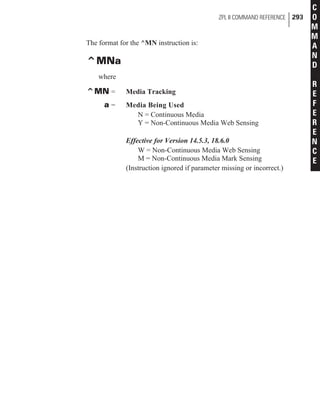
[^FO - Set field origin relative to label home.]
[^B3 - Select Code 39 bar code.]
[^FN2 - Assign field number 2.]
[^FS - End of field data.]
^XZ
[^XZ- Indicates end of format.]
^XA
[^XA - Indicates start of label format.]
^XFFORMAT^FS
[^XF - Recall stored format.]
[FORMAT - Name of format to be recalled.]
[^FS - End of field data.]
Instructions continued on next page.
52 CHAPTER 4
ZPL II Programming Exercises](https://image.slidesharecdn.com/manuallenguajezebra-150520210931-lva1-app6892/85/Manual-lenguaje-zebra-61-320.jpg)
![^FN1^FDZEBRA^FS
[^FN1 - Indicate following data should be inserted
in area allocated for field number 1.]
[^FD - Indicate start of field data.]
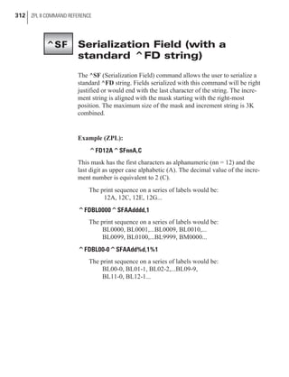
[ZEBRA - Field data.]
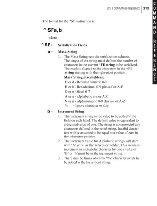
[^FS - End of field data.]
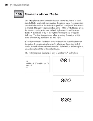
^FN2^FDAAA001^FS
[^FN2 - Indicate following data should be inserted
in area allocated for field number 2.]
[^FD - Indicates start of field data.]
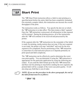
[AAA001 - Field data.]
[^FS - End of field data.]
^XZ
[^XZ- Indicates end of format.]
^XA
[^XA - Indicates start of label format.]
^XFFORMAT^FS
[^XF - Recall stored format.]
[FORMAT - Name of format to be recalled.]
[^FS - End of field data.]
^FN1^FDBEARS^FS
[^FN1 - Indicates following data should be inserted
in area allocated for field number 1.]
[^FD - Indicates start of field data.]
[BEARS - Field data.]
[^FS - End of field data.]
^FN2^FDZZZ999^FS
[^FN2 - Indicates following data should be inserted
in area allocated for field number 2.]
[^FD - Indicates start of field data.]
[ZZZ999 - Field data.]
[^FS - End of field data.]
CHAPTER 4 53
ZPL II Programming Exercises](https://image.slidesharecdn.com/manuallenguajezebra-150520210931-lva1-app6892/85/Manual-lenguaje-zebra-62-320.jpg)
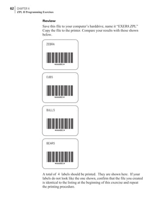
![^XZ
[^XZ- Indicates end of format.]
Review
Save this file to your computer’s harddrive, name it “EXER6.ZPL”
Copy the file to the printer. Compare your results with those shown
below.
If your labels do not look like the ones shown, confirm that the file
you created is identical to the listing at the beginning of this exercise
and repeat the printing procedure.
54 CHAPTER 4
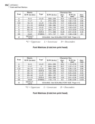
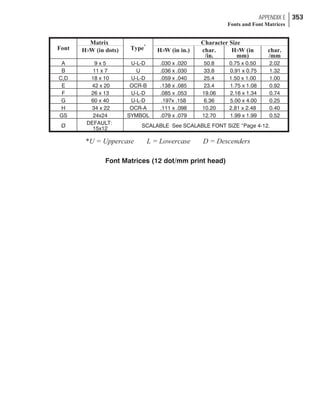
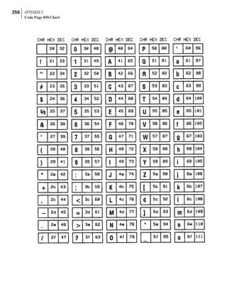
ZPL II Programming Exercises](https://image.slidesharecdn.com/manuallenguajezebra-150520210931-lva1-app6892/85/Manual-lenguaje-zebra-63-320.jpg)
![Programming Instructions
Type the instructions (shown in bold) in the order given. An explana-
tion of what each instruction does is in brackets.
^XA
[^XA - Indicates start of label format.]
^EF^FS
[^EF - Erase all previously stored formats.]
[^FS - End of field data.]
^XZ
[^XZ- Indicates end of format.]
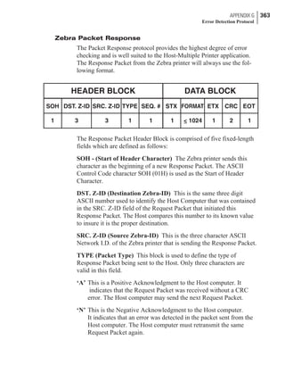
^XFFORMAT^FS
[^XF - Recall stored format.]
[FORMAT - Name of format to be recalled.]
[^FS - End of field data.]
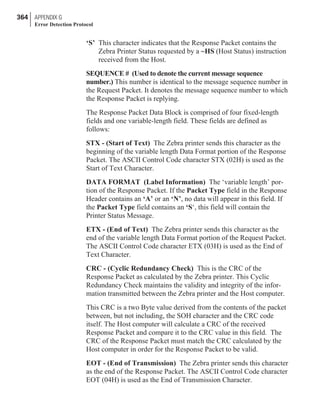
^FN1^FDBEARS^FS
[^FN1 - Indicates following data should be inserted
in area allocated for field number 1.]
[^FD - Indicates start of field data.]
[BEARS - Field data.]
[^FS - End of field data.]
^FN2^FDZZZ999^FS
[^FN2 - Indicates following data should be inserted
in area allocated for field number 2.]
[^FD - Indicates start of field data.]
[ZZZ999 - Field data.]
[^FS - End of field data.]
^FO30,30^CFF^FDNO FORMAT TO RECALL^FS
[^FO30,30 - Set field origin relative to label home.]
[^CFF - Change to font “F”.]
[^FD - Indicates start of field data.]
Instructions continued on next page.
56 CHAPTER 4
ZPL II Programming Exercises](https://image.slidesharecdn.com/manuallenguajezebra-150520210931-lva1-app6892/85/Manual-lenguaje-zebra-65-320.jpg)
![[NO FORMAT TO RECALL - Field data.]
[^FS - End of field data.]
^XZ
[^XZ- Indicates end of format.]
Review
Save this file to your computer’s harddrive, name it “EXER7.ZPL”
Copy the file to the printer. Compare your results with those shown
below.
If your label does not look like the one shown, confirm that the file
you created is identical to the listing at the beginning of this exercise
and repeat the printing procedure.
CHAPTER 4 57
ZPL II Programming Exercises](https://image.slidesharecdn.com/manuallenguajezebra-150520210931-lva1-app6892/85/Manual-lenguaje-zebra-66-320.jpg)
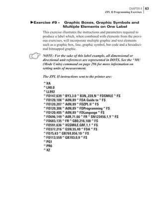
![Programming Instructions
Type the instructions (shown in bold) in the order given. An explana-
tion of what each instruction does is in brackets.
^XA^MCY^XZ
[^XA - Indicates start of label format.]
[^MCY - Map Clear ]
[^XZ - End of format.]
^XA
[^XA - Indicates start of label format.]
^LH30,30
[^LH - Sets label home position 30 dots to right and 30
dots down from top edge of label.]
^FO20,10^AF^FVZEBRA^FS
[^FO - Set field origin relative to label home. ]
[^AF - Select font “F.”]
[^FV - Indicates start of VARIABLE field data.]
[ZEBRA - Variable data.]
[^FS - End of field data. ]
^FO20,60^B3N,,100^FDAAA001^FS
[^FO - Set field origin relative to label home.]
[^B3 - Select Code 39 bar code.]
[^FD - Start of field data for bar code.]
[AAA001 - Actual field data.]
[^FS - End of field data.]
^MCN
[^MCN - Set Map Clear to N=No.]
^XZ
[^XZ - End of format.]
CHAPTER 4 59
ZPL II Programming Exercises](https://image.slidesharecdn.com/manuallenguajezebra-150520210931-lva1-app6892/85/Manual-lenguaje-zebra-68-320.jpg)
![^XA
[^XA - Indicates start of label format.]
^FO20,10^AF^FVCUBS^FS
[^FO - Set field origin relative to label home. ]
[^AF - Select font “F.”]
[^FV - Indicates start of VARIABLE field data.]
[CUBS- Variable data.]
[^FS - End of field data.]
^XZ
[^XZ - End of format.]
^XA
[^XA - Indicates start of label format.]
^FO20,10^AF^FVBULLS^FS
[^FO - Set field origin relative to label home. ]
[^AF - Select font “F.”]
[^FV - Indicates start of VARIABLE field data.]
[BULLS - Variable data.]
[^FS - End of field data.]
^XZ
[^XZ - End of format.]
^XA
[^XA - Indicates start of label format.]
^FO20,10^AF^FVBEARS^FS
[^FO - Set field origin relative to label home. ]
[^AF - Select font “F.”]
[^FV - Indicates start of VARIABLE field data.]
[BEARS - Variable data.]
[^FS - End of field data.]
Instructions continued on next page.
60 CHAPTER 4
ZPL II Programming Exercises](https://image.slidesharecdn.com/manuallenguajezebra-150520210931-lva1-app6892/85/Manual-lenguaje-zebra-69-320.jpg)
![^XZ
[^XZ - End of format.]
^XA^MCY^XZ
[^XA - Indicates start of label format.]
[^MCY - Map Clear ]
[^XZ - End of format.]
CHAPTER 4 61
ZPL II Programming Exercises](https://image.slidesharecdn.com/manuallenguajezebra-150520210931-lva1-app6892/85/Manual-lenguaje-zebra-70-320.jpg)
![Programming Instructions
Type the instructions (shown in bold) in the order given. An explana-
tion of what each instruction does is in brackets ( [ ] ).
^XA
[^XA - Indicates start of label format.]
^LH0,0
[^LH - Sets label home position at the upper left corner of
the label.]
^LL992
[^LL - Sets label length to 992 dots rows along the Y-axis.]
^FO147,639^BY3,3.0^B3N,,228,N^FDSMILE^FS
[^FO - Set field origin relative to label home.]
[^BY - Set Bar Code Field Default values to 3 dots for
narrow bar width and wide bar to narrow bar
width ratio to 3.0 units.]
[^B3N,,228,N - Select Code 39 bar code. Do not calculate
check digit, set bar code height to 228 dots,
do not print interpretation line.]
[^FD - Start of field data for bar code.]
[SMILE- Actual field data.]
[^FS - End of field data.]
^FO120,108^A0N,89^FDA Guide to^FS
[^FO - Set field origin relative to label home.]
[^A0 - Select default font “0”, normal orientation,
character height of 89 dots, standard width.]
[^FD - Start of field data.]
[A Guide to - Actual field data.]
[^FS - End of field data.]
^FO120,207^A0N,89^FDZPL II^FS
[^FO - Set field origin relative to label home.]
[^A0 - Select default font “0”, normal orientation,
character height of 89 dots, standard width.]
[^FD - Start of field data.]
[ZPL II - Actual field data.]
[^FS - End of field data.]
64 CHAPTER 4
ZPL II Programming Exercises](https://image.slidesharecdn.com/manuallenguajezebra-150520210931-lva1-app6892/85/Manual-lenguaje-zebra-73-320.jpg)
![^FO120,306^A0N,89^FDProgramming^FS
[^FO - Set field origin relative to label home.]
[^A0 - Select default font “0”, normal orientation,
character height of 89 dots, standard width.]
[^FD - Start of field data.]
[Programming - Actual field data.]
[^FS - End of field data.]
^FO120,405^A0N,89^FDLanguage^FS
[^FO - Set field origin relative to label home.]
[^A0 - Select default font “0”, normal orientation,
character height of 89 dots, standard width.]
[^FD - Start of field data.]
[Language - Actual field data.]
[^FS - End of field data.]
^FO696,149^A0R,71,66^FR^SN123456,1,Y^FS
[^FO - Set field origin relative to label home.]
[^A0R - Select default font “0”, rotated 90 degrees
clockwise, character height of 71 dots,
character width of 66 dots.]
[^FR - Set field to be reverse print as white letters.]
[^SN123456,1,Y- Define serialized field, starting value of
123456, increment by 1, insert leading zeros.]
[^FS - End of field data.]
^FO683,135^FR^GB0,216,108^FS
[^FO - Set field origin relative to label home.]
[^FR - Set field (box for serial numbers) to be reverse print
as black.]
[^GB0,216,108 - Set graphic box to be width of 0, height of
216 dots, 108 dots thick (same as specifying width).]
[^FS - End of field data.]
^FO591,636^XGR:SMILE.GRF,1,1^FS
[^FO - Set field origin relative to label home.]
[^XGSMILE.GRF,1,1 - Recall SMILE.GRF graphic from
printer memory, magnification factor of 1 on the
X-axis and 1 on the Y-axis.]
[^FS - End of field data.]
CHAPTER 4 65
ZPL II Programming Exercises](https://image.slidesharecdn.com/manuallenguajezebra-150520210931-lva1-app6892/85/Manual-lenguaje-zebra-74-320.jpg)
![^FO377,216^GSN,55,40^FDA^FS
[^FO - Set field origin relative to label home.]
[^GSN,55,40 - Set graphic symbol with normal orientation
to be height of 55 dots, width of 40 dots.]
[^FDA - Select field data of registered trademark character.]
[^FS - End of field data.]
^FO75,63^GB769,856,10^FS
[^FO - Set field origin relative to label home.]
[^GB769,856,10 - Set graphic box (large box around
perimeter of label) to be width of 769 dots,
height of 856 dots and 10 dots thick.]
[^FS - End of field data.]
^FO113,559^GB703,0,9^FS
[^FO - Set field origin relative to label home.]
[^GB703,0,9 - Set graphic line (horizontal line near middle
of label) to be width of 703 dots,
height of 0 dots and 9 dots thick.]
[^FS - End of field data.]
^PQ1
[^PQ1 - Set print quantity of 1 label.]
^PR6
[^PR6 - Set print rate at 6 inches per second.]
^XZ
[^XZ - Indicates end of label format.]
66 CHAPTER 4
ZPL II Programming Exercises](https://image.slidesharecdn.com/manuallenguajezebra-150520210931-lva1-app6892/85/Manual-lenguaje-zebra-75-320.jpg)

![Programming Instructions
Type the instructions (shown in bold) in the order given. An explana-
tion of what each instruction does is in brackets.
^XA
[^XA - Indicates start of label format.]
^IDR:SMILE.GRF
[^ID - Delete the image called SMILE from memory.]
^XZ
[^XZ - Indicates end of label format.]
^XA
[^XA - Indicates start of label format.]
^FO50,50^XGR:SMILE.GRF
[This line attempts to call the graphic image that was
just deleted. If the deletion was successful, only the
following line will print.]
^FO50,90^AF^FDLOOK, NO SMILE^FS
[^FO - Set field origin relative to label home.
[^AF - Select font “F.”]
[^FD - Start of field data.]
[LOOK, NO SMILE - Actual field data.]
[^FS - End of field data.]
^XZ
[^XZ - Indicates end of label format.]
CHAPTER 4 69
ZPL II Programming Exercises](https://image.slidesharecdn.com/manuallenguajezebra-150520210931-lva1-app6892/85/Manual-lenguaje-zebra-78-320.jpg)


![ZPL II COMMAND REFERENCE 107
C
O
M
M
A
N
D
R
E
F
E
R
E
N
C
E
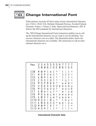
ASCII Code 39
@ %V
A A
B B
C C
D D
E E
F F
G G
H H
I I
J J
K K
L L
M M
N N
O O
P P
Q Q
R R
S S
T T
U U
V V
W W
X X
Y Y
Z Z
[ %K
%L
]
%M
%N
_ %O
(B) Code 39 Full ASCII MODE
ASCII Code 39
‘ %W
a +A
b +B
c +C
d +D
e +E
f +F
g +G
h +H
i +I
j +J
k +K
l +L
m +M
n +M
o +O
p +P
q +Q
r +R
s +S
t +T
u +U
v +V
w +W
x +X
y +Y
z +Z
{ %P
| %Q
} %R
~ %S
DEL %T, %X](https://image.slidesharecdn.com/manuallenguajezebra-150520210931-lva1-app6892/85/Manual-lenguaje-zebra-116-320.jpg)
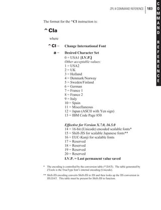
![Field Data
Set
Unshifted
Character Set
Shift 1
Character Set
Shift 2
Character Set
0 0 ’
1 1 ESC ;
2 2 FS <
3 3 GS =
4 4 RS >
5 5 US ?
6 6 ! @
7 7 “ [
8 8 #
9 9 & ]
A A SOH a
B B STX b
C C ETX c
D D EOT d
E E ENQ e
F F ACK f
G G BEL g
H H BS h
I I HT i
J J LF j
K K VT k
L L FF l
M M CR m
N N SO n
O O SI o
P P DLE p
Q Q DC1 q
R R DC2 r
S S DC3 s
T T DC4 t
U U NAK u
V V SYN v
W W ETB w
X X CAN x
Y Y EM y
Z Z SUB z
- - ( _
. . ) ‘
space space Null DEL
$ $ * {
/ / , |
++ ++ : }
% % reserved ~
< (Shift 1)
> (Shift 2)
: (N.A.)
; (N.A.)
? (N.A.)
= (Numeric Shift)
Code 49 Shift 1 & 2 Character Substitutions
110 ZPL II COMMAND REFERENCE](https://image.slidesharecdn.com/manuallenguajezebra-150520210931-lva1-app6892/85/Manual-lenguaje-zebra-119-320.jpg)

![ZPL II COMMAND REFERENCE 123
C
O
M
M
A
N
D
R
E
F
E
R
E
N
C
E
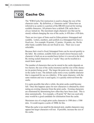
ASCII Code 93
‘ ‘W
a )A
b )B
c )C
d )D
e )E
f )F
g )G
h )H
i )I
j )J
k )K
l )L
m )M
n )M
o )O
p )P
q )Q
r )R
s )S
t )T
u )U
v )V
w )W
x )X
y )Y
z )Z
{ ‘P
| ‘Q
} ‘R
~ ‘S
DEL ‘T
ASCII Code 93
@ ‘V
A A
B B
C C
D D
E E
F F
G G
H H
I I
J J
K K
L L
M M
N N
O O
P P
Q Q
R R
S S
T T
U U
V V
W W
X X
Y Y
Z Z
[ ‘K
‘L
]
‘M
‘N
_ ‘O
(B) Code 93 Full ASCII MODE](https://image.slidesharecdn.com/manuallenguajezebra-150520210931-lva1-app6892/85/Manual-lenguaje-zebra-132-320.jpg)
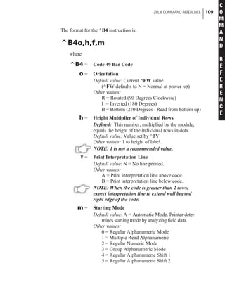
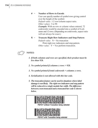
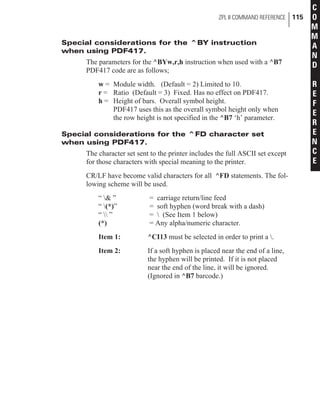
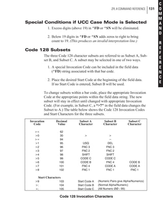
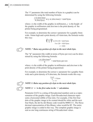
![Effective for Version 16.3.0
Other value: A = Automatic Mode
The Automatic Mode analyzes the data sent and
automatically determines the best packing
method. Full ASCII Character Set can be used in
the ^FD statement. Printer will determine when
to shift subsets. A string of four or more numeric
digits will cause automatic shift to subset C.
130 ZPL II COMMAND REFERENCE
Value Code A Code B Code C
0 SP SP 00
1 ! ! 01
2 ‘’ ‘’ 02
3 # # 03
4 $ $ 04
5 % % 05
6 & & 06
7 ‘ ‘ 07
8 ( ( 08
9 ) ) 09
10 * * 10
11 ++ ++ 11
12 , , 12
13 - - 13
14 . . 14
15 / / 15
16 0 0 16
17 1 1 17
18 2 2 18
19 3 3 19
20 4 4 20
21 5 5 21
22 6 6 22
23 7 7 23
24 8 8 24
25 9 9 25
26 : : 26
27 ; ; 27
28 < < 28
29 = = 29
30 > > 30
31 ? ? 31
32 @ @ 32
33 A A 33
34 B B 34
35 C C 35
36 D D 36
37 E E 37
38 F F 38
39 G G 39
40 H H 40
41 I I 41
42 J J 42
43 K K 43
44 L L 44
45 M M 45
46 N N 46
47 O O 47
48 P P 48
49 Q Q 49
50 R R 50
51 S S 51
52 T T 52
Value Code A Code B Code C
53 U U 53
54 V V 54
55 W W 55
56 X X 56
57 Y Y 57
58 Z Z 58
59 [ [ 59
60 60
61 ] ] 61
62 62
63 _ _ 63
64 NUL . 64
65 SOH a 65
66 STX b 66
67 ETX c 67
68 EOT d 68
69 ENQ e 69
70 ACK f 70
71 BEL g 71
72 BS h 72
73 HT i 73
74 LF j 74
75 VT k 75
76 FF l 76
77 CR m 77
78 SO n 78
79 SI o 79
80 DLE p 80
81 DC1 q 81
82 DC2 r 82
83 DC3 s 83
84 DC4 t 84
85 NAK u 85
86 SYN v 86
87 ETB w 87
88 CAN x 88
89 EM y 89
90 SUB z 90
91 ESC { 91
92 FS | 92
93 GS } 93
94 RS ~ 94
95 US DEL 95
96 FNC3 FNC3 96
97 FNC2 FNC2 97
98 SHIFT SHIFT 98
99 Code C Code C 99
100 Code B FNC4 Code B
101 FNC4 Code A Code A
102 FNC1 FNC1 FNC1
103 START (Code A)
104 START (Code B)
105 START (Code C)
Code 128 Character Sets](https://image.slidesharecdn.com/manuallenguajezebra-150520210931-lva1-app6892/85/Manual-lenguaje-zebra-139-320.jpg)


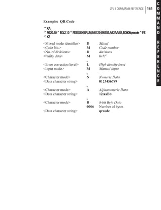


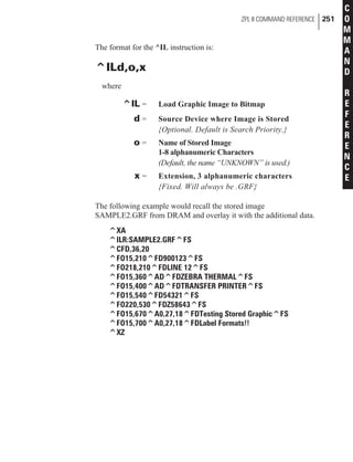


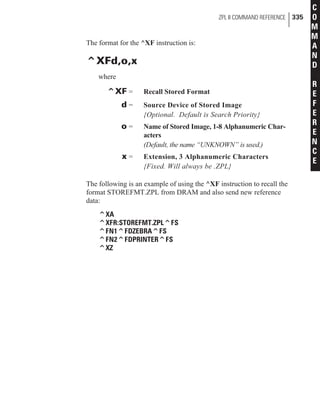
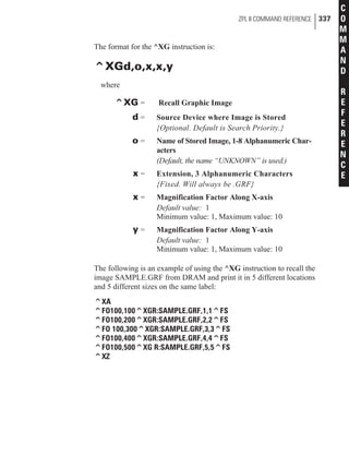
![The format for the ^LR instruction is:
^LRa
where
^LR = Label Reverse Print
a = Reverse Print All Fields
Y = Yes
N = No {I.V.P. = N}
[Instruction is ignored if no parameter given.]
{I.V.P. = Last permanent value saved}
NOTE 1: The ^LR will remain active unless turned off by ^LRN
instruction or the printer is powered down.
NOTE 2: The effects of an ^LR instruction will not be seen unless
fields overlap as shown in the above example.
NOTE 3: Only fields that come after this instruction will be affected.
ZPL II COMMAND REFERENCE 281
C
O
M
M
A
N
D
R
E
F
E
R
E
N
C
E](https://image.slidesharecdn.com/manuallenguajezebra-150520210931-lva1-app6892/85/Manual-lenguaje-zebra-290-320.jpg)


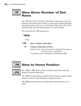
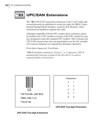
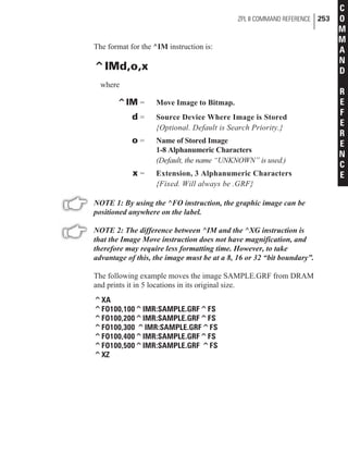
![Printing Mirror Image of Label
The ^PM (Print Mirror Image of Label) instruction prints the entire
printable area of the label as a mirror image. This instruction flips the
image from left to right.
The format for the ^PM instruction is:
^PMa
where
^PM = Print Mirror Image
a = Mirror Print Entire Label
Y = Yes
N = No {I.V.P. = N}
[Instruction is ignored if no parameter given.]
The following is an example of how to use the ^PM instruction.
NOTE: The ^PM will remain active unless turned off by ^PMN
instruction or the printer is powered down.
ZPL II COMMAND REFERENCE 301
C
O
M
M
A
N
D
R
E
F
E
R
E
N
C
E
^PM](https://image.slidesharecdn.com/manuallenguajezebra-150520210931-lva1-app6892/85/Manual-lenguaje-zebra-310-320.jpg)


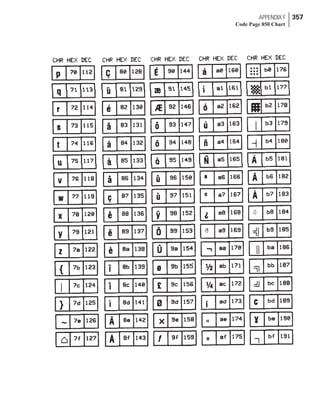
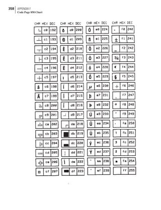
![ASCII Code Chart
346 APPENDIX B
ASCII Code Chart
HEX CHAR HEX CHAR HEX CHAR HEX CHAR
00 NUL 20 space 40 @ 60 ‘
01 SOH 21 ! 41 A 61 a
02 STX 22 “ 42 B 62 b
03 ETX 23 # 43 C 63 c
04 EOT 24 $ 44 D 64 d
05 ENQ 25 % 45 E 65 e
06 ACK 26 & 46 F 66 f
07 BEL 27 ‘ 47 G 67 g
08 BS 28 ( 48 H 68 h
09 HT 29 ) 49 I 69 i
0A LF 2A * 4A J 6A j
0B VT 2B + 4B K 6B k
0C FF 2C , 4C L 6C l
0D CR 2D - 4D M 6D m
0E SO 2E . 4E N 6E n
0F SI 2F / 4F O 6F o
10 DLE 30 0 50 P 70 p
11 DC1 31 1 51 Q 71 q
12 DC2 32 2 52 R 72 r
13 DC3 33 3 53 S 73 s
14 DC4 34 4 54 T 74 t
15 NAK 35 5 55 U 75 u
16 SYN 36 6 56 V 76 v
17 ETB 37 7 57 W 77 w
18 CAN 38 8 58 X 78 x
19 EM 39 9 59 Y 79 y
1A SUB 3A : 5A Z 7A z
1B ESC 3B ; 5B [ 7B {
1C FS 3C < 5C 7C |
1D GS 3D = 5D ] 7D }
1E RS 3E > 5E ^ 7E ~
1F US 3F ? 5F _ 7F DEL
NOTE: NOT recommended for use as a Command Prefix,
Format Prefix, or Delimiter Character](https://image.slidesharecdn.com/manuallenguajezebra-150520210931-lva1-app6892/85/Manual-lenguaje-zebra-355-320.jpg)


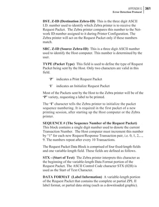
![Code for Calculating the CRC for the
Zebra Protocol
/********************************************************
*
* name: do_crc_ccitt
*
* description: Calculates a 16 bit cyclic redundancy check
* character using the CCITT polynomial
* X**16 + X**12 + X**5 + 1 which translates
* to the magic number 0x1021.
*
* parameters: crc -- the check character that is being
* accumulated.
* chr -- the character being added to the crc
*
* returns: the new crc
*
*
* date: 26 September 1991
*
********************************************************/
const UWORD ccitt_table[256] =
{
/* 0 -- */ 0x0000, 0x1021, 0x2042, 0x3063, 0x4084, 0x50A5, 0x60C6, 0x70E7,
/* 8 -- */ 0x8108, 0x9129, 0xA14A, 0xB16B, 0xC18C, 0xD1AD, 0xE1CE, 0xF1EF,
/* 16 -- */ 0x1231, 0x0210, 0x3273, 0x2252, 0x52B5, 0x4294, 0x72F7, 0x62D6,
/* 24 -- */ 0x9339, 0x8318, 0xB37B, 0xA35A, 0xD3BD, 0xC39C, 0xF3FF, 0xE3DE,
/* 32 -- */ 0x2462, 0x3443, 0x0420, 0x1401, 0x64E6, 0x74C7, 0x44A4, 0x5485,
/* 40 -- */ 0xA56A, 0xB54B, 0x8528, 0x9509, 0xE5EE, 0xF5CF, 0xC5AC, 0xD58D,
/* 48 -- */ 0x3653, 0x2672, 0x1611, 0x0630, 0x76D7, 0x66F6, 0x5695, 0x46B4,
/* 56 -- */ 0xB75B, 0xA77A, 0x9719, 0x8738, 0xF7DF, 0xE7FE, 0xD79D, 0xC7BC,
/* 64 -- */ 0x48C4, 0x58E5, 0x6886, 0x78A7, 0x0840, 0x1861, 0x2802, 0x3823,
/* 72 -- */ 0xC9CC, 0xD9ED, 0xE98E, 0xF9AF, 0x8948, 0x9969, 0xA90A, 0xB92B,
/* 80 -- */ 0x5AF5, 0x4AD4, 0x7AB7, 0x6A96, 0x1A71, 0x0A50, 0x3A33, 0x2A12,
/* 88 -- */ 0xDBFD, 0xCBDC, 0xFBBF, 0xEB9E, 0x9B79, 0x8B58, 0xBB3B, 0xAB1A,
/* 96 -- */ 0x6CA6, 0x7C87, 0x4CE4, 0x5CC5, 0x2C22, 0x3C03, 0x0C60, 0x1C41,
/* 104 -- */ 0xEDAE, 0xFD8F, 0xCDEC, 0xDDCD, 0xAD2A, 0xBD0B, 0x8D68, 0x9D49,
/* 112 -- */ 0x7E97, 0x6EB6, 0x5ED5, 0x4EF4, 0x3E13, 0x2E32, 0x1E51, 0x0E70,
APPENDIX G 371
Error Detection Protocol](https://image.slidesharecdn.com/manuallenguajezebra-150520210931-lva1-app6892/85/Manual-lenguaje-zebra-380-320.jpg)
![/* 120 -- */ 0xFF9F, 0xEFBE, 0xDFDD, 0xCFFC, 0xBF1B, 0xAF3A, 0x9F59, 0x8F78,
/* 128 -- */ 0x9188, 0x81A9, 0xB1CA, 0xA1EB, 0xD10C, 0xC12D, 0xF14E, 0xE16F,
/* 136 -- */ 0x1080, 0x00A1, 0x30C2, 0x20E3, 0x5004, 0x4025, 0x7046, 0x6067,
/* 144 -- */ 0x83B9, 0x9398, 0xA3FB, 0xB3DA, 0xC33D, 0xD31C, 0xE37F, 0xF35E,
/* 152 -- */ 0x02B1, 0x1290, 0x22F3, 0x32D2, 0x4235, 0x5214, 0x6277, 0x7256,
/* 160 -- */ 0xB5EA, 0xA5CB, 0x95A8, 0x8589, 0xF56E, 0xE54F, 0xD52C, 0xC50D,
/* 168 -- */ 0x34E2, 0x24C3, 0x14A0, 0x0481, 0x7466, 0x6447, 0x5424, 0x4405,
/* 176 -- */ 0xA7DB, 0xB7FA, 0x8799, 0x97B8, 0xE75F, 0xF77E, 0xC71D, 0xD73C,
/* 184 -- */ 0x26D3, 0x36F2, 0x0691, 0x16B0, 0x6657, 0x7676, 0x4615, 0x5634,
/* 192 -- */ 0xD94C, 0xC96D, 0xF90E, 0xE92F, 0x99C8, 0x89E9, 0xB98A, 0xA9AB,
/* 200 -- */ 0x5844, 0x4865, 0x7806, 0x6827, 0x18C0, 0x08E1, 0x3882, 0x28A3,
};
static UWORD do_crc_ccitt ( UWORD crc, UBYTE in_char )
{
crc = (UWORD)( crc << 8 ) ^ ccitt_table [ ( crc >> 8 ) ^ in_char ] ;
return ( crc ) ;
}
372 APPENDIX G
Error Detection Protocol](https://image.slidesharecdn.com/manuallenguajezebra-150520210931-lva1-app6892/85/Manual-lenguaje-zebra-381-320.jpg)


![SCRM[1]](https://cdn.slidesharecdn.com/ss_thumbnails/6541d089-07f6-4578-95aa-2aba974be43e-151012061047-lva1-app6892-thumbnail.jpg?width=640&height=640&fit=bounds)


