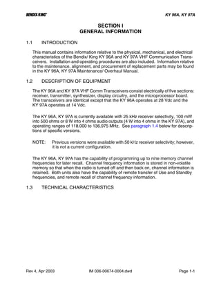
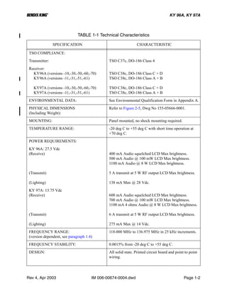
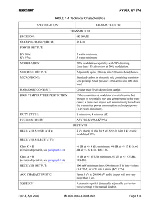
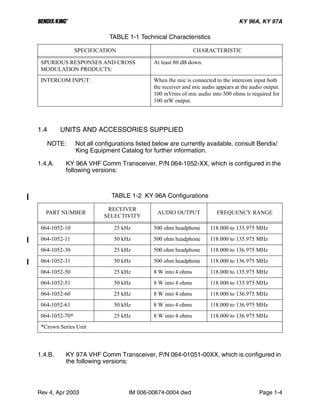
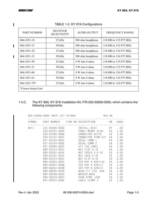
SlideShare a Scribd company logo
1 of 42
Download to read offline
INSTALLATION MANUAL
KY 96A, KY 97A
VHF COMMUNICATION
TRANSCEIVER
MANUAL NUMBER 006-00674-0004
Revision 4, April 2003
h
WARNING
THE ENCLOSED TECHNICAL DATA IS ELIGIBLE FOR EXPORT UNDER LICENSE DES-
IGNATION NLR AND IS TO BE USED SOLELY BY THE INDIVIDUAL/ ORGANIZATION
TO WHOM IT IS ADDRESSED. DIVERSION CONTRARY TO U.S. LAW IS PROHIBITED.
COPYRIGHT NOTICE
©1989, 1994, 1996, 2003 HONEYWELL INTERNATIONAL INC.
REPRODUCTION OF THIS PUBLICATION OR ANY PORTION THEREOF BY ANY
MEANS WITHOUT THE EXPRESS WRITTEN PERMISSION OF HONEYWELL IS
PROHIBITED. FOR FURTHER INFORMATION CONTACT THE MANAGER, TECHNICAL
PUBLICATIONS, HONEYWELL, ONE TECHNOLOGY CENTER, 23500 WEST 105TH
STREET OLATHE KS 66061 TELEPHONE: (913) 782-0400.
B KY 96A, KY 97A
Rev 4, Apr 2003 IM 006-00674-0004.dwd RH-1
REVISION HISTORY
INSTALLATION MANUAL
BENDIX/KING
KY 96A, KY 97A
VHF Communication Transceiver
PART NUMBER REV DATE DESCRIPTION
---------------------------------------------------------------------------------------------------------------------
006-00674-0004 4 Apr/2003
006-00674-0003 3 Apr/1994
006-00674-0002 2 Jan/1994
006-00674-0001 1 Oct/1989
B KY 96A, KY 97A
Rev 4, Apr 2003 IM 006-00674-0004.dwd RH-2
THIS PAGE RESERVED
B TABLE OF CONTENTS KY 96A, KY 97A
Rev 4, Apr 2003 MM 006-00674-0004.dwd TOC-1
SECTION I
GENERAL INFORMATION
Paragraph Page
1.1 Introduction .............................................................................................1-1
1.2 Description of Equipment.........................................................................1-1
1.3 Technical Characteristics.........................................................................1-1
1.4 Units and Accessories Supplied ..............................................................1-4
1.5 Accessories Required, But Not Supplied.................................................1-6
1.6 License Requirements.............................................................................1-6
1.7 Continued Airworthiness..........................................................................1-6
LIST OF TABLES
Table Page
1-1 Technical Characteristics.........................................................................1-2
1-2 KY 96A Configurations ............................................................................1-4
1-3 KY 97A Configurations ............................................................................1-5
SECTION II
INSTALLATION
Paragraph Page
2.1 General....................................................................................................2-1
2.2 Unpacking and Inspection Equipment .....................................................2-1
2.3 Equipment Installation .............................................................................2-1
2.4 Post Installation Checks ..........................................................................2-4
LIST OF TABLES
Table Page
2-1 Compatible Installations...........................................................................2-2
LIST OF ILLUSTRATIONS
Figure Page
2-1 KY 96A, KY 97A Cover-On Adjustments..... ...........................................2-5
2-2 KY 96A Pin Function and Location Diagram ...........................................2-6
2-3 KY 97A Pin Function and Location Diagram ...........................................2-7
2-4 Molex Terminal and Tools ........................... ...........................................2-8
2-5 KY 96A, KY 97A Outline and Mounting ....... Dwg 155-05666-0001......2-11
2-6 KY 96A, KY 97A Installation Assembly........ Dwg 155-05690-0000......2-13
2-7 Connector (P/N 030-00101-0002 R-9) Assembly..................................2-15
2-8 KY 96A Interconnect.................................... Dwg 155-01583-0000......2-17
B TABLE OF CONTENTS KY 96A, KY 97A
Rev 4, Apr 2003 IM 006-00674-0004.dwd TOC-2
2-9 KY 97A Interconnect.................................... Dwg 155-01583-0001......2-19
2-10 Dual KY 96A Interconnect ........................... Dwg 155-01584-0000......2-21
2-11 Dual KY 97A Interconnect ........................... Dwg 155-01584-0001......2-23
2-12 Dual KY 96A with KA 25 Interconnect ......... Dwg 155-01585-0000......2-25
2-13 Dual KY 97A with KA 25 Interconnect ......... Dwg 155-01585-0001......2-27
SECTION III
OPERATION
Paragraph Page
3.1 Power On Unit .........................................................................................3-1
3.2 Transmit Indicator....................................................................................3-1
3.3 Modes of Operation .................................................................................3-1
3.4 Remote Frequency Transfer....................................................................3-3
3.5 Remote Channel Increment.....................................................................3-3
3.6 Dim Select ...............................................................................................3-3
LIST OF ILLUSTRATIONS
Figure Page
3-1 KY 96A, KY 97A Controls....................... ................................................3-4
APPENDIX E
ENVIRONMENTAL QUALIFICATION FORMS
LIST OF ILLUSTRATIONS
Figure Page
E-1 KY 96A Environmental Qualification Form ............................................. E-3
E-2 KY 97A Environmental Qualification Form ............................................. E-4
B KY 96A, KY 97A
Rev 4, Apr 2003 IM 006-00674-0004.dwd Page 1-1
SECTION I
GENERAL INFORMATION
1.1 INTRODUCTION
This manual contains information relative to the physical, mechanical, and electrical
characteristics of the Bendix/ King KY 96A and KY 97A VHF Communication Trans-
ceivers. Installation and operating procedures are also included. Information relative
to the maintenance, alignment, and procurement of replacement parts may be found
in the KY 96A, KY 97A Maintenance/ Overhaul Manual.
1.2 DESCRIPTION OF EQUIPMENT
The KY 96A and KY 97A VHF Comm Transceivers consist electrically of five sections:
receiver, transmitter, synthesizer, display circuitry, and the microprocessor board.
The transceivers are identical except that the KY 96A operates at 28 Vdc and the
KY 97A operates at 14 Vdc.
The KY 96A, KY 97A is currently available with 25 kHz receiver selectivity, 100 mW
into 500 ohms or 8 W into 4 ohms audio outputs (4 W into 4 ohms in the KY 97A), and
operating ranges of 118.000 to 136.975 MHz. See paragraph 1.4 below for descrip-
tions of specific versions.
NOTE: Previous versions were available with 50 kHz receiver selectivity; however,
it is not a current configuration.
The KY 96A, KY 97A has the capability of programming up to nine memory channel
frequencies for later recall. Channel frequency information is stored in non-volatile
memory so that when the radio is turned off and then back on, channel information is
retained. Both units also have the capability of remote transfer of Use and Standby
frequencies, and remote recall of channel frequency information.
1.3 TECHNICAL CHARACTERISTICS
B KY 96A, KY 97A
Rev 4, Apr 2003 IM 006-00674-0004.dwd Page 1-2
TABLE 1-1 Technical Characteristics
SPECIFICATION CHARACTERISTIC
TSO COMPLIANCE:
Transmitter: TSO C37c, DO-186 Class 4
Receiver:
KY96A (versions -10,-30,-50,-60,-70)
KY96A (versions -11,-31,-51,-61)
KY97A (versions -10,-30,-50,-60,-70)
KY97A (versions -11,-31,-51,-61)
TSO C38c, DO-186 Class C + D
TSO C38c, DO-186 Class A + B
TSO C38c, DO-186 Class C + D
TSO C38c, DO-186 Class A + B
ENVIRONMENTAL DATA: See Environmental Qualification Form in Appendix A.
PHYSICAL DIMENSIONS
(Including Weight):
Refer to Figure 2-5, Dwg No 155-05666-0001.
MOUNTING: Panel mounted, no shock mounting required.
TEMPERATURE RANGE: -20 deg C to +55 deg C with short time operation at
+70 deg C.
POWER REQUIREMENTS:
KY 96A: 27.5 Vdc
(Receive)
(Transmit)
(Lighting)
400 mA Audio squelched LCD Max brightness.
500 mA Audio @ 100 mW LCD Max brightness.
1100 mA Audio @ 8 W LCD Max brightness.
5 A transmit at 5 W RF output LCD Max brightness.
138 mA Max @ 28 Vdc.
KY 97A: 13.75 Vdc
(Receive)
(Transmit)
(Lighting)
600 mA Audio squelched LCD Max brightness.
700 mA Audio @ 100 mW LCD Max brightness.
1100 mA 4 ohms Audio @ 8 W LCD Max brightness.
6 A transmit at 5 W RF output LCD Max brightness.
275 mA Max @ 14 Vdc.
FREQUENCY RANGE:
(version dependent, see paragraph 1.4)
118.000 MHz to 136.975 MHz in 25 kHz increments.
FREQUENCY STABILITY: 0.0015% from -20 deg C to +55 deg C.
DESIGN: All solid state. Printed circuit board and point to point
wiring.
B KY 96A, KY 97A
Rev 4, Apr 2003 IM 006-00674-0004.dwd Page 1-3
TRANSMITTER
EMISSION: 6K 00A3E
OCCUPIED BANDWIDTH: 25 kHz
POWER OUTPUT:
KY 96A:
KY 97A:
5 watts minimum
5 watts minimum
MODULATION: 70% modulation capability with 98% limiting.
Less than 15% distortion at 70% modulation.
SIDETONE OUTPUT: Adjustable up to 100 mW into 500 ohms headphones.
MICROPHONE: Standard carbon or dynamic mic containing transistor-
ized preamp. Must provide 100 mVrms into 100 ohm
load.
HARMONIC CONTENT: Greater than 60 dB down from carrier.
HIGH TEMPERATURE PROTECTION: If the transmitter or modulator circuits become hot
enough to potentially hurt any components in the trans-
ceiver, a protection circuit will automatically turn down
the transmitter power consumption and output power
(1.25 watts minimum).
DUTY CYCLE: 1 minute on, 4 minutes off.
FCC IDENTIFIER: ASY7BL KY96A,KY97A
RECEIVER
RECEIVER SENSITIVITY: 2 uV (hard) or less for 6 dB S+N/N with 1 kHz tone
modulated 30%.
RECEIVER SELECTIVITY:
Class C + D
(version dependent, see paragraph 1.4)
Class A + B
(version dependent, see paragraph 1.4)
-6 dB at +/- 8 kHz minimum. 40 dB at +/- 17 kHz. 60
dB at +/- 22 kHz. DO-186.
-6 dB at +/- 15 kHz minimum. 60 dB at +/- 43 kHz.
DO-186.
RECEIVER OUTPUT: 100 mW minimum into 500 ohms or 8 W into 4 ohms
(KY 96A) or 4 W into 4 ohms (KY 97A).
AGC CHARACTERISTIC: From 5 uV to 20,000 uV audio output will not vary
more than 3 dB.
SQUELCH: Automatic squelch (internally adjustable carrier-to-
noise setting) with manual disable.
TABLE 1-1 Technical Characteristics
SPECIFICATION CHARACTERISTIC
B KY 96A, KY 97A
Rev 4, Apr 2003 IM 006-00674-0004.dwd Page 1-4
1.4 UNITS AND ACCESSORIES SUPPLIED
NOTE: Not all configurations listed below are currently available, consult Bendix/
King Equipment Catalog for further information.
1.4.A. KY 96A VHF Comm Transceiver, P/N 064-1052-XX, which is configured in the
following versions:
1.4.B. KY 97A VHF Comm Transceiver, P/N 064-01051-00XX, which is configured in
the following versions:
SPURIOUS RESPONSES AND CROSS
MODULATION PRODUCTS:
At least 80 dB down.
INTERCOM INPUT: When the mic is connected to the intercom input both
the receiver and mic audio appears at the audio output.
100 mVrms of mic audio into 500 ohms is required for
100 mW output.
TABLE 1-2 KY 96A Configurations
PART NUMBER
RECEIVER
SELECTIVITY
AUDIO OUTPUT FREQUENCY RANGE
064-1052-10 25 kHz 500 ohm headphone 118.000 to 135.975 MHz
064-1052-11 50 kHz 500 ohm headphone 118.000 to 135.975 MHz
064-1052-30 25 kHz 500 ohm headphone 118.000 to 136.975 MHz
064-1052-31 50 kHz 500 ohm headphone 118.000 to 136.975 MHz
064-1052-50 25 kHz 8 W into 4 ohms 118.000 to 135.975 MHz
064-1052-51 50 kHz 8 W into 4 ohms 118.000 to 135.975 MHz
064-1052-60 25 kHz 8 W into 4 ohms 118.000 to 136.975 MHz
064-1052-61 50 kHz 8 W into 4 ohms 118.000 to 136.975 MHz
064-1052-70* 25 kHz 8 W into 4 ohms 118.000 to 136.975 MHz
*Crown Series Unit
TABLE 1-1 Technical Characteristics
SPECIFICATION CHARACTERISTIC
B KY 96A, KY 97A
Rev 4, Apr 2003 IM 006-00674-0004.dwd Page 1-5
1.4.C. The KY 96A, KY 97A Installation Kit, P/N 050-02600-0000, which contains the
following components:
050-02600-0000 INSTL KIT KY196A REV AA
---------------------------------------------------------------
SYMBOL PART NUMBER FIND NO DESCRIPTION UM -0000
---------------------------------------------------------------
REF1 155-05690-0000 INSTALL ASSY RF .00
030-00101-0002 PANEL MOUNT PLUG EA 1.00
030-01094-0080 CONNECTOR KEYED EA 1.00
030-01107-0031 CONNECTOR TERM 31T EA 1.00
057-02193-0001 DECAL COMM 1 EA 1.00
057-02193-0002 DECAL COMM 2 EA 1.00
057-05944-0003 KIT TSO LABEL EA 1.00
089-02013-0037 NUT FLAT 6-32 EA 1.00
089-02051-0024 NUT SPEED U 6-32 EA 4.00
089-02191-0022 NUT LOCK 6-32 EA 1.00
089-02353-0001 NUT CLIP 6-32 EA 6.00
089-05903-0007 SCR PHP 4-40X7/16 EA 2.00
089-05907-0008 SCR PHP 6-32X1/2 EA 1.00
089-06012-0008 SCR FHP 6-32X1/2 EA 6.00
089-08094-0030 WSHR FLT STD .446 EA 1.00
089-08168-0002 WASHER WAVE EA 1.00
090-00019-0007 RING RTNR .438 EA 1.00
091-00072-0002 CABLE CLAMP 2 EA 1.00
TABLE 1-3 KY 97A Configurations
PART NUMBER
RECEIVER
SELECTIVITY
AUDIO OUTPUT FREQUENCY RANGE
064-1051-10 25 kHz 500 ohm headphone 118.000 to 135.975 MHz
064-1051-11 50 kHz 500 ohm headphone 118.000 to 135.975 MHz
064-1051-30 25 kHz 500 ohm headphone 118.000 to 136.975 MHz
064-1051-31 50 kHz 500 ohm headphone 118.000 to 136.975 MHz
064-1051-50 25 kHz 4 W into 4 ohms 118.000 to 135.975 MHz
064-1051-51 50 kHz 4 W into 4 ohms 118.000 to 135.975 MHz
064-1051-60 25 kHz 4 W into 4 ohms 118.000 to 136.975 MHz
064-1051-61 50 kHz 4 W into 4 ohms 118.000 to 136.975 MHz
064-1051-70* 25 kHz 4 W into 4 ohms 118.000 to 136.975 MHz
*Crown Series Unit
B KY 96A, KY 97A
Rev 4, Apr 2003 IM 006-00674-0004.dwd Page 1-6
1.5 ACCESSORIES REQUIRED, BUT NOT SUPPLIED
1.5.A. Communications antenna and cables.
1.5.B. Headphones: 500 ohm nominal impedance.
1.5.C. Microphone: Low impedance carbon or dynamic with transistorized preamp.
1.5.D. For 13.75 V operation of the KY 96A a 14-to-28 V convertor such as KGS Elec-
tronics Model RB-125 or equivalent may be used. The RB-125 is available from
Bendix/ King under P/N 068-01016-0003.
1.6 LICENSE REQUIREMENTS
The transmitter, as installed in the aircraft, requires an Aircraft Radio Station License.
This license is obtained by filing FCC Form 404, Aircraft Radio Station License Appli-
cation, which may be obtained from your local FCC Field Office. The KY 96A, KY 97A
may be operated for up to 30 days without a station license after filing Form 404 while
awaiting the receipt of the radio license if a copy of FCC Form 404 is kept in the air-
craft.
NOTE: This equipment has been type accepted by the FCC and entered on their
list of type accepted equipment as AlliedSignal KY 96A/97A, and must
be identified as AlliedSignal KY 96A/97A on FCC Form 404.
CAUTION: THE VHF TRANSMITTER IN THIS EQUIPMENT IS GUARANTEED TO
MEET FEDERAL COMMUNICATIONS COMMISSION ACCEPTANCE
OVER THE OPERATING TEMPERATURE RANGE ONLY WHEN A
BENDIX/ KING CRYSTAL IS USED IN THE STABILIZED MASTER OS-
CILLATOR. USE OF OTHER THAN A BENDIX/ KING CRYSTAL IS
CONSIDERED AN UNAUTHORIZED MODIFICATION AND MAY VOID
THE WARRANTY.
NOTE: The Federal Communications Commission requires that the operator of
the transmitter of this equipment hold a Restricted Radio Telephone Op-
erator Permit (FCC Form 753) or higher class license. A permit may be
obtained by a U.S. citizen from the nearest field office of the FCC; no ex-
amination is required.
1.7 CONTINUED AIRWORTHINESS
The instructions for continued airworthiness in the TC or STC approvals for this prod-
uct supplements or supersedes the instructions for continued airworthiness in this
manual.
This Bendix/ King product KY 96A, KY 97A is designed and manufactured to allow on-
condition maintenance. On-condition maintenance is described as follows. There are
no periodic service requirements necessary to maintain continued airworthiness. No
maintenance is required until the equipment does not properly perform its intended
B KY 96A, KY 97A
Rev 4, Apr 2003 IM 006-00674-0004.dwd Page 1-7
function. When service is required, a complete performance test must be accom-
plished following any repair action. Consult the appropriate section of the Mainte-
nance Manual for complete performance test information.
B KY 96A, KY 97A
Rev 4, Apr 2003 IM 006-00674-0004.dwd Page 1-8
THIS PAGE RESERVED
B KY 96A, KY 97A
Rev 4, Apr 2003 IM 006-00674-0004.dwd Page 2-1
SECTION II
INSTALLATION
2.1 GENERAL
This section contains suggestions and factors to consider before installing the KY 96A,
KY 97A. Close adherence to these suggestions will assure more satisfactory perfor-
mance from the equipment.
The conditions and test required for the TSO and MOPS approval of this article are
minimum performance standards. It is the responsibility of those installing this article
either on or with a specified type or class of aircraft to determine that the aircraft instal-
lation conditions are within the TSO and MOPS standards. These articles must have
separate approval for installation in an aircraft. Any features in this equipment outside
the requirements of this applicable TSO and MOPS must be evaluated and approved
as part of the installation approval. The article may be installed only if performed under
14 CFR part 43 or the applicable airworthiness requirements.
2.2 UNPACKING AND INSPECTING EQUIPMENT
Unpack the equipment carefully and inspect each item for evidence of damage in-
curred during shipment. If a damage claim must be filed, save the shipping container
and all packing materials to substantiate your claim. The claim should be filed with the
transportation company as soon as possible. The shipping container and packing
should be saved in any case in the event that storage or reshipment of the equipment
is necessary.
2.3 EQUIPMENT INSTALLATION
The KY 96A, KY 97A installation will conform to standards designated by the custom-
er, installing agency, and existing conditions as to the unit location and type of instal-
lation. However, the following suggestions should be considered before installing the
KY 96A, KY 97A. The installing agency will supply and fabricate all external cables.
The connectors required are supplied by Bendix/ King. Connector pin function dia-
grams are included in this manual as Figure 2-2, and Figure 2-3. Interconnect dia-
grams are included in this manual as Figure 2-8 through Figure 2-13. Refer to the ta-
ble below for compatible installations.
B KY 96A, KY 97A
Rev 4, Apr 2003 IM 006-00674-0004.dwd Page 2-2
NOTE: Use good quality stranded wire with at least 600 V insulation that will not
support a flame.
2.3.1 Avionics Cooling Requirements for Panel Mounted Equipment
The most important contribution to improved reliability of avionics equipment is to limit
the maximum operating temperature of each unit. While modern designs consume
less total energy, the heat dissipated per unit volume (watts/cubic inch) remains much
the same due to contemporary high density packaging techniques. While each indi-
vidual unit may or may not require forced air cooling, the combined heat generated by
several units operating in a typical panel or rack can significantly degrade the reliability
of the equipment if provisions for adequate cooling are not incorporated in the initial
installation.
2.3.2 Mounting Rack Installation
2.3.2.A. The KY 96A, KY 97A is mounted rigidly in the aircraft panel. Select a position
in the panel that is not too close to any high external heat source. Remember
to allow adequate space for installation of cables and connectors. Avoid sharp
bends and placing the cables too near the aircraft control cables.
2.3.2.B. When installing two or more panel mounted units in a stack, the mounting
trays shall be spaced 0.050 inches (0.127 cm) apart. Current production
mounting trays have 0.025 inch (0.064 cm) dimples built in to top and bottom
and both sides so that the trays will automatically be spaced properly.
2.3.2.C. Refer to Figure 2-5 for the KY 96A, KY 97A mounting dimensions. Mark and
cut the mounting holes.
2.3.2.D. Secure the mounting rack to the instrument panel per Figure 2-5 and Figure
2-6. The rear mounting bosses should be attached to the airframe by means
of support brackets.
2.3.3 Antenna Installation
A conventional 50 ohm vertically polarized comm antenna is required with the KY 96A,
KY 97A. Vertical bent whip antennas are not recommended. Wideband comm anten-
TABLE 2-1 Compatible Installations
CURRENT INSTALLATION
KY196A KY197A KY196 KY197
KY96A Compatible YES*1 NO NO NO
KY97A Compatible NO YES*1 NO NO
*1 Will work but backlighting will be too bright and unsuitable, and the audio amplifier
will not function because the current installation is not wired for an audio amplifier.
B KY 96A, KY 97A
Rev 4, Apr 2003 IM 006-00674-0004.dwd Page 2-3
nas provide efficient operation over the comm band. Antennas should be installed per
manufacturer’s recommendations. Additional recommendations are as follows:
2.3.3.A. Mount antenna on a flat metal surface or install a ground plane at least 18
inches square.
2.3.3.B. The antenna should be well removed from any projections and the engine(s)
and propeller(s). Also, for satisfactory operation, the antenna isolation be-
tween a communications transmitter antenna and a nav receiver antenna, as
well as between dual comm antennas, should be a minimum of 30 dB. VHF
antennas mounted on top and bottom have approximately 30 dB isolation. A
horizontally polarized nav antenna and a vertically polarized comm antenna
will have practical values from 10 to 30 dB.
2.3.3.C. If both comm antennas must be top mounted or both bottom mounted, anten-
na isolation between comms may not be adequate to prevent re-radiation. In
single audio panel installations, re-radiation can be prevented by use of the
XMT-REC interlock. Refer to Installation Bulletin #194. In dual audio panel
installations where simultaneous operation of both comms is desired, the
XMT-REC interlock is not recommended.
2.3.4 Cable Harness and Connector Assembly
The KY 96A, KY 97A uses a special connector that mates directly with the printed cir-
cuit board inside the unit. Assembly of the connector is as follows:
2.3.4.A. Contact Terminal Assembly using Molex Crimper (see Figure 2-4)
2.3.4.A.1 Strip each wire 5/32 inch for contact terminal, P/N 030-01107-00XX. (The last
two digits of the part number indicates the number of terminals required).
2.3.4.A.2 Open the Molex HT 1921 hand crimper with the engraved side toward the op-
erator. Place the conductor tab section of a contact terminal on Anvil A with
the contact portion facing away from the operator. Close the crimper slightly
until the contact tabs touch the female jaw.
2.3.4.A.3 Insert the stripped conductor until the insulation is even with the side of the
crimper facing the operator. Crimp the conductor tabs by squeezing the han-
dles together until the jaws are fully closed or a sufficient crimp is obtained.
2.3.4.A.4 Move the lead to Anvil A. Place the insulating tab section on Anvil A. Crimp
again until the jaws are fully closed or until a sufficient crimp is obtained.
2.3.4.B. Contact Insertion into Molex Connector Housing
After the contact terminals have been installed on the wiring harness, the contact ter-
minals can be inserted into the proper location in the connector housing (P/N 030-
01094-0080). The terminal cannot be inserted upside down. Be sure to push the ter-
minal all the way in until a click can be felt or heard. The self-locking feature can be
tested by gently pulling on the wire.
2.3.4.C. Location of Polarizing Key in Housing
B KY 96A, KY 97A
Rev 4, Apr 2003 IM 006-00674-0004.dwd Page 2-4
Prior to insertion of connector into rear of unit, check polarizing key position between
contacts 8 and 9. Refer to Figure 2-6 to check correct position of polarizing key.
2.3.4.D. Extraction of Contact from Molex Connector
2.3.4.D.1 Slip the flat narrow blade of a Molex HT-1884 contact ejector tool, P/N 047-
05099-0001, under the contact on the mating side of the connector. By turn-
ing the connector upside down one can see the blade slide into the stop.
2.3.4.D.2 When the ejector is slid into place, the retaining tab of the contact is raised,
allowing the contact to be removed by pulling moderately on the lead.
2.3.4.D.3 Neither the contact or position is damaged by removing a contact; however,
the contact should be visually checked before reinstalling to be certain that re-
taining tab “A” extends as shown in Figure 2-4 for retention in connector.
2.3.4.E. Coax Connector
Refer to Figure 2-7 for instructions for mounting the right angle coaxial BNC connector
to the coax cable. Install the connector into the mounting rack.
2.3.5 KY 96A, KY 97A Installation
2.3.5.A. Looking at the top of the unit, make sure the front lobe of the hold down device
is in a vertical position.
2.3.5.B. Slide the unit into the mounting rack until the front lobe touches the mounting
rack.
2.3.5.C. Insert a 3/32 inch Allen wrench through the hole in the front panel to engage
the locking screw. Turn clockwise until the rear lobe engages the mounting
rack. Continue turning until the unit is secure in the mounting rack. DO NOT
OVERTIGHTEN.
2.3.5.D. To remove the unit turn the locking screw counterclockwise, using a 3/32 inch
Allen wrench, until the unit disengages from the mounting rack. Pull the unit
out of the mounting rack by pulling on the metal tabs located behind the front
panel on each side of the unit.
2.4 POST INSTALLATION CHECKS
An operational performance flight test is recommended after the installation is com-
pleted to insure satisfactory performance of the equipment in its normal environment.
Check all aircraft control movements to be sure no electrical cables interfere with their
operation. To check the communications transceiver, maintain an appropriate altitude
and contact a ground station facility at a range of at least 50 nautical miles. Then con-
tact a ground station close in. Pull the volume control out to defeat the automatic
squelch feature and listen for any unusual electrical noise which would reduce the
comm receiver sensitivity by increasing the squelch threshold. If possible, verify the
communications capability on both the high and low end of the VHF comm band.
B KY 96A, KY 97A
Rev 4, Apr 2003 IM 006-00674-0004.dwd Page 2-5
CAUTION: BEFORE FLIGHT, CHECK THE ANTENNA VSWR. THIS SHOULD BE
CHECKED WITH AN IN-LINE TYPE WATTMETER INSERTED IN THE
COAXIAL TRANSMISSION LINE BETWEEN THE TRANSCEIVER
AND THE ANTENNA. ANY PROBLEM WITH THE ANTENNA INSTAL-
LATION WILL MOST LIKELY BE SEEN AS A HIGH REFLECTED POW-
ER. VSWR OF 3:1 WILL RESULT IN A 25% LOSS OF POWER.
NOTE: The LCD back lighting can be set for the most pleasing intensity by ad-
justing the panel lighting. See paragraph 3.6 of this manual for dim se-
lect.
2.4.1 Adjustments
The KY 96A, KY 97A are factory adjusted to accommodate typical requirements for
most aircraft configurations. However, baseline mic gain, sidetone, carrier/noise
squelch, and carrier squelch may be adjusted through the cover for specific aircraft
configurations. See Figure 2-1.
FIGURE 2-1 KY 96A, KY 97A Cover-On Adjustments
B KY 96A, KY 97A
Rev 4, Apr 2003 IM 006-00674-0004.dwd Page 2-6
FIGURE 2-2 KY 96A Pin Function and Location Diagram
B KY 96A, KY 97A
Rev 4, Apr 2003 IM 006-00674-0004.dwd Page 2-7
FIGURE 2-3 KY 97A Pin Function and Location Diagram
B KY 96A, KY 97A
Rev 4, Apr 2003 IM 006-00674-0004.dwd Page 2-8
FIGURE 2-4 Molex Terminal and Tools (Sheet 1 of 3)
B KY 96A, KY 97A
Rev 4, Apr 2003 IM 006-00674-0004.dwd Page 2-9
FIGURE 2-4 Molex Terminal and Tools (Sheet 2 of 3)
B KY 96A, KY 97A
Rev 4, Apr 2003 IM 006-00674-0004.dwd Page 2-10
FIGURE 2-4 Molex Terminal and Tools (Sheet 3 of 3)
B KY 96A, KY 97A
Rev 4, Apr 2003 IM 006-00674-0004.dwd Page 2-11
FIGURE 2-5 KY 96A, KY 97A Outline and Mounting Drawing
(Dwg No 155-05666-0001 Rev AB)
B KY 96A, KY 97A
Rev 4, Apr 2003 IM 006-00674-0004.dwd Page 2-13
FIGURE 2-6 KY 96A, KY 97A Installation Assembly Drawing
(Dwg No 155-05690-0000 Rev 4)
B KY 96A, KY 97A
Rev 4, Apr 2003 IM 006-00674-0004.dwd Page 2-15
FIGURE 2-7 Connector (P/N 030-00101-0002 R-9) Assembly
B KY 96A, KY 97A
Rev 4, Apr 2003 IM 006-00674-0004.dwd Page 2-16
THIS PAGE RESERVED
B KY 96A, KY 97A
Rev 4, Apr 2003 IM 006-00674-0004.dwd Page 2-17
FIGURE 2-8 KY 96A interconnect
(Dwg No 155-01583-0000 Rev AA)
B KY 96A, KY 97A
Rev 4, Apr 2003 IM 006-00674-0004.dwd Page 2-19
FIGURE 2-9 KY 97A interconnect
(Dwg No 155-01583-0001 Rev AA)
B KY 96A, KY 97A
Rev 4, Apr 2003 IM 006-00674-0004.dwd Page 2-21
FIGURE 2-10 Dual KY 96A interconnect
(Dwg No 155-01584-0000 Rev AA)
B KY 96A, KY 97A
Rev 4, Apr 2003 IM 006-00674-0004.dwd Page 2-23
FIGURE 2-11 Dual KY 97A interconnect
(Dwg No 155-01584-0001 Rev AA)
B KY 96A, KY 97A
Rev 4, Apr 2003 IM 006-00674-0004.dwd Page 2-25
FIGURE 2-12 Dual KY 96A with KA 25A interconnect
(Dwg No 155-01585-0000 Rev AA)
B KY 96A, KY 97A
Rev 4, Apr 2003 IM 006-00674-0004.dwd Page 2-27
FIGURE 2-13 Dual KY 97A with KA 25A interconnect
(Dwg No 155-01585-0001 Rev AA)
B KY 96A, KY 97A
Rev 4, Apr 2003 IM 006-00674-0004.dwd Page 3-1
SECTION III
OPERATION
3.1 POWER ON UNIT
To power on the unit, rotate the Volume (VOL) knob clockwise from the OFF position.
When power is activated the Use and Standby (STBY) windows will display the fre-
quencies and/or mode stored in the non-volatile memory before power down. After ac-
tivating power, pull the VOL knob out to override the automatic squelch and rotate the
VOL knob to the desired audio level. Push the VOL knob back in to activate the auto-
matic squelch.
CAUTION: THE KY 96A, KY 97A SHOULD BE POWERED ON ONLY AFTER EN-
GINE STARTUP. THIS IS A SIMPLE PRECAUTION WHICH HELPS
PROTECT THE SOLID STATE CIRCUITRY AND EXTENDS THE OP-
ERATING LIFE OF YOUR AVIONICS EQUIPMENT.
3.2 TRANSMIT INDICATOR
During Comm transmissions, a TX will appear between the USE and STBY windows
to indicate that the transceiver is in the Transmit mode of operation.
3.3 MODES OF OPERATION
3.3.A. Frequency Mode
Frequency selection is accomplished in the Standby Entry mode by changing the fre-
quency display in the STBY window of the display with the tuning knobs, and then
transferring the selected frequency into the USE window by pressing the Transfer but-
ton. The larger tuning knob will increment or decrement the MHz portion of the display
in 1 MHz steps with rollover at each band edge (118.000 MHz or 135.975 MHz). The
smaller tuning knob will increment or decrement the kHz portion of the display in 50
kHz steps with the knob pushed in or in 25 kHz steps with the knob pulled out. While
in the Standby Entry mode, the transceiver remains tuned to the frequency displayed
in the USE window at all times.
NOTE: Extended Frequency units will rollover at 118.000 and 136.975 MHz.
3.3.B. Channel Mode
Momentarily pressing the Channel (CHAN) button while in the Frequency mode puts
the radio in the Channel mode. The last active frequency remains tuned and displayed
in the USE window. The last used channel number is displayed in the channel digit
unless no channels have been programmed, in which case the radio defaults to Chan-
nel 1 and dashes are displayed in the STBY window. Turning either tuning knob
changes the channel number and corresponding frequency in the STBY window. The
channels will only increment and decrement to channels that have been programmed.
If there has been no activity for five seconds the radio will return to Frequency mode
and the channel frequency is placed in the STBY window. Pressing the CHAN button
B KY 96A, KY 97A
Rev 4, Apr 2003 IM 006-00674-0004.dwd Page 3-2
before the five second delay is completed will return the radio to the Frequency mode
and the status of the Frequency mode prior to entering Channel mode remains the
same.
When in Channel mode, pressing the Transfer button will return the radio to Frequency
mode. The channel frequency will become the new USE frequency and the last USE
frequency will become the new STBY frequency. If the radio was in Direct Tune mode
(see paragraph 3.3.E below) prior to entering Channel mode, pressing the Transfer
button or allowing the radio to time out will bring it back to Standby Entry.
3.3.C. Program Mode
The Program mode is entered by pressing and holding the CHAN button for longer
than two seconds. The last active frequency remains tuned and displayed in the USE
window. The last used channel is displayed when Program mode is entered. The
channel number flashes and turning either tuning knob changes the channel number.
Pressing the Transfer button will cause the frequency associated with that channel to
flash. The tuning knobs then work as in the Frequency mode, except that between the
rollover points (118.XX and 135.XX or 136.XX) dashes are displayed. These dashes
are used to de-program channels, and to display a channel that is unprogrammed.
When the channel frequency is flashing, pressing the Transfer button will cause the
frequency to stop flashing and the channel number to start flashing at which time a
new channel may be selected for programming.
3.3.D. Program Secure Mode
Program Secure mode is used to secure or lock the frequency that is assigned to a
channel so that the frequency assigned to that channel cannot be changed. All chan-
nels or individual channels can be Program Secured. The following list of operations
is given to Program Secure or Un-Program Secure a channel:
To Program Secure a Channel
* Hold the CHAN button in for more than 2 seconds (Program mode).
* Momentarily press the Transfer button (flashing frequency).
* Change channel frequency to desired Program Secured frequency.
* Ground the Program Secure pin (TP 701).
* Momentarily press the Transfer button (Flashing channel number).
* Unground the Program Secure pin.
To Un-Program Secure a Channel
* Hold the CHAN button in for more than 2 seconds (Program mode).
* Ground the Program Secure pin (TP 701).
* Momentarily press the Transfer button (flashing frequency).
* Unground the Program Secure pin.
* Momentarily press the Transfer button (Flashing channel number).
3.3.E. Direct Tune Mode
B KY 96A, KY 97A
Rev 4, Apr 2003 IM 006-00674-0004.dwd Page 3-3
The Direct Tune mode is entered from the Standby Frequency Entry mode or Channel
mode by pushing the Transfer button for longer than 2 seconds. The tuning knobs op-
erate as in Standby Frequency Entry, but will change the USE frequency, rather than
the STBY frequency. The radio will be tuned to the Active frequency.
Momentarily pushing the Transfer button returns the radio to Standby Frequency En-
try. The Standby frequency prior to Active Entry mode remains unchanged.
3.4 REMOTE FREQUENCY TRANSFER (J96A pin 11 or J97A pin 12)
The Remote Frequency Transfer button operates identically to the front panel Transfer
button with the exception that holding the Remote Transfer button for two seconds
does not place the radio in the Active Entry mode.
3.5 REMOTE CHANNEL INCREMENT (J96A, J97A pin L)
Pressing the Remote Channel button will cause the system to enter the Channel mode
of operation and will increment the channel from the previous channel number used.
3.6 DIM SELECT (J96A, J97A pin A)
When Dim Select is in the open position, display backlight dimming will track a 14 V
lighting bus. When Dim Select is connected to ground the display backlight brightness
tracks or follows a 28 V lighting bus. When Dim Select is connected to the aircraft sup-
ply voltage the display backlighting will be at half brightness.
B KY 96A, KY 97A
Rev 4, Apr 2003 IM 006-00674-0004.dwd Page 3-4
FIGURE 3-1 KY 96A, KY 97A Controls
B KY 96A, KY 97A
Rev 4, Apr 2003 IM 006-00674-0004.dwd Page E-1
APPENDIX E
ENVIRONMENTAL QUALIFICATION FORMS
B KY 96A, KY 97A
Rev 4, Apr 2003 IM 006-00674-0004.dwd Page E-2
THIS PAGE RESERVED
B KY 96A, KY 97A
Rev 4, Apr 2003 IM 006-00674-0004.dwd Page E-3
FIGURE E-1 KY 96A Environmental Qualification Form
B KY 96A, KY 97A
Rev 4, Apr 2003 IM 006-00674-0004.dwd Page E-4
FIGURE E-2 KY 97A Environmental Qualification Form

More Related Content

Viewers also liked

Aircraft Communication Topic 3 radio components
Aircraft Communication  Topic 3 radio componentsAircraft Communication  Topic 3 radio components
Aircraft Communication Topic 3 radio componentsIzah Asmadi
 
Aircraft Communication Topic 2 modulation and propagation of radio waves
Aircraft Communication  Topic 2 modulation and propagation of radio wavesAircraft Communication  Topic 2 modulation and propagation of radio waves
Aircraft Communication Topic 2 modulation and propagation of radio wavesIzah Asmadi
 
Topic 1 basic radio wave properties
Topic 1 basic radio wave propertiesTopic 1 basic radio wave properties
Topic 1 basic radio wave propertiesIzah Asmadi
 
Aircraft Communication Topic 9 vhf omni range (vor)
Aircraft Communication  Topic 9 vhf omni range (vor)Aircraft Communication  Topic 9 vhf omni range (vor)
Aircraft Communication Topic 9 vhf omni range (vor)Izah Asmadi
 
Aircraft Communication Topic 10 instrument landing systems
Aircraft Communication Topic 10 instrument landing systemsAircraft Communication Topic 10 instrument landing systems
Aircraft Communication Topic 10 instrument landing systemsIzah Asmadi
 
Aircraft Communication Topic 6 pa system
Aircraft Communication  Topic 6 pa systemAircraft Communication  Topic 6 pa system
Aircraft Communication Topic 6 pa systemIzah Asmadi
 
Aircraft Communication Topic 4 vhf communication system
Aircraft Communication  Topic 4 vhf communication systemAircraft Communication  Topic 4 vhf communication system
Aircraft Communication Topic 4 vhf communication systemIzah Asmadi
 
Aircraft communication-systems
Aircraft communication-systemsAircraft communication-systems
Aircraft communication-systemsKrishikesh Singh
 
Manual de-instalaciones-electricas-mod. 3
Manual de-instalaciones-electricas-mod. 3Manual de-instalaciones-electricas-mod. 3
Manual de-instalaciones-electricas-mod. 3Noni Gus
 

Viewers also liked (13)

Aircraft Communication Topic 3 radio components
Aircraft Communication  Topic 3 radio componentsAircraft Communication  Topic 3 radio components
Aircraft Communication Topic 3 radio components
 
Aircraft Communication Topic 2 modulation and propagation of radio waves
Aircraft Communication  Topic 2 modulation and propagation of radio wavesAircraft Communication  Topic 2 modulation and propagation of radio waves
Aircraft Communication Topic 2 modulation and propagation of radio waves
 
Topic 1 basic radio wave properties
Topic 1 basic radio wave propertiesTopic 1 basic radio wave properties
Topic 1 basic radio wave properties
 
RADAR AND ANTENNA
RADAR AND ANTENNARADAR AND ANTENNA
RADAR AND ANTENNA
 
Doppler VHF Omni Directional Range (DVOR)
Doppler VHF Omni Directional Range (DVOR)Doppler VHF Omni Directional Range (DVOR)
Doppler VHF Omni Directional Range (DVOR)
 
Aircraft Communication Topic 9 vhf omni range (vor)
Aircraft Communication  Topic 9 vhf omni range (vor)Aircraft Communication  Topic 9 vhf omni range (vor)
Aircraft Communication Topic 9 vhf omni range (vor)
 
Aircraft Communication Topic 10 instrument landing systems
Aircraft Communication Topic 10 instrument landing systemsAircraft Communication Topic 10 instrument landing systems
Aircraft Communication Topic 10 instrument landing systems
 
Aircraft Communication Topic 6 pa system
Aircraft Communication  Topic 6 pa systemAircraft Communication  Topic 6 pa system
Aircraft Communication Topic 6 pa system
 
Aircraft Communication Topic 4 vhf communication system
Aircraft Communication  Topic 4 vhf communication systemAircraft Communication  Topic 4 vhf communication system
Aircraft Communication Topic 4 vhf communication system
 
VHF Communication Basics Part 3
VHF Communication  Basics Part 3VHF Communication  Basics Part 3
VHF Communication Basics Part 3
 
Aircraft communication-systems
Aircraft communication-systemsAircraft communication-systems
Aircraft communication-systems
 
Manual de-instalaciones-electricas-mod. 3
Manual de-instalaciones-electricas-mod. 3Manual de-instalaciones-electricas-mod. 3
Manual de-instalaciones-electricas-mod. 3
 
Radar ppt
Radar pptRadar ppt
Radar ppt
 

Similar to Manual de instalacion bendix ky96a

Stahl G053 Wireless Receiver Repeater EK00 III Data Sheet
Stahl G053 Wireless Receiver Repeater EK00 III Data SheetStahl G053 Wireless Receiver Repeater EK00 III Data Sheet
Stahl G053 Wireless Receiver Repeater EK00 III Data SheetThorne & Derrick International
 
Bang gia mccb_compact_nsx_schneider_2012
Bang gia mccb_compact_nsx_schneider_2012Bang gia mccb_compact_nsx_schneider_2012
Bang gia mccb_compact_nsx_schneider_2012Lãng Quên
 
Combined Mobile Radio spec
Combined  Mobile Radio specCombined  Mobile Radio spec
Combined Mobile Radio specirene steenhagen
 
AUDIO FREQUENCY TRACK CIRCUITS
AUDIO FREQUENCY TRACK CIRCUITSAUDIO FREQUENCY TRACK CIRCUITS
AUDIO FREQUENCY TRACK CIRCUITSsspardesh
 
High Density Signal Conditioners From Acromag
High Density Signal Conditioners From AcromagHigh Density Signal Conditioners From Acromag
High Density Signal Conditioners From AcromagM.S. Jacobs & Associates
 
High Density I/O Modules for Industrial Process Control
High Density I/O Modules for Industrial Process ControlHigh Density I/O Modules for Industrial Process Control
High Density I/O Modules for Industrial Process ControlInstrument Specialties, Inc.
 
Siemens MV GIS Switchgear
Siemens MV GIS SwitchgearSiemens MV GIS Switchgear
Siemens MV GIS Switchgearmichaeljmack
 
Accoustic Rhythm
Accoustic RhythmAccoustic Rhythm
Accoustic Rhythmangieknows
 
ANAVIEW Class-D Amplifier AMS1000-2600
ANAVIEW Class-D Amplifier  AMS1000-2600ANAVIEW Class-D Amplifier  AMS1000-2600
ANAVIEW Class-D Amplifier AMS1000-2600HTCS LLC
 
Dienhathe.com miniature circuit breakers
Dienhathe.com miniature circuit breakersDienhathe.com miniature circuit breakers
Dienhathe.com miniature circuit breakersDien Ha The
 
Gelbyson Christie K Series MagAmp Power Supplies
Gelbyson Christie K Series MagAmp Power SuppliesGelbyson Christie K Series MagAmp Power Supplies
Gelbyson Christie K Series MagAmp Power Suppliesgelbyson
 
4903-0010 - Conventional Strobe with Horn.pdf
4903-0010 - Conventional Strobe with Horn.pdf4903-0010 - Conventional Strobe with Horn.pdf
4903-0010 - Conventional Strobe with Horn.pdfSourovSamadder
 
Nidec asi soft starters-mv-e
Nidec asi soft starters-mv-eNidec asi soft starters-mv-e
Nidec asi soft starters-mv-eNidec Corporation
 
Accoustic Junkies
Accoustic JunkiesAccoustic Junkies
Accoustic Junkiesangieknows
 

Similar to Manual de instalacion bendix ky96a (20)

Stahl G053 Wireless Receiver Repeater EK00 III Data Sheet
Stahl G053 Wireless Receiver Repeater EK00 III Data SheetStahl G053 Wireless Receiver Repeater EK00 III Data Sheet
Stahl G053 Wireless Receiver Repeater EK00 III Data Sheet
 
Bang gia mccb_compact_nsx_schneider_2012
Bang gia mccb_compact_nsx_schneider_2012Bang gia mccb_compact_nsx_schneider_2012
Bang gia mccb_compact_nsx_schneider_2012
 
AN-9754
AN-9754AN-9754
AN-9754
 
Combined Mobile Radio spec
Combined  Mobile Radio specCombined  Mobile Radio spec
Combined Mobile Radio spec
 
AUDIO FREQUENCY TRACK CIRCUITS
AUDIO FREQUENCY TRACK CIRCUITSAUDIO FREQUENCY TRACK CIRCUITS
AUDIO FREQUENCY TRACK CIRCUITS
 
High Density Signal Conditioners From Acromag
High Density Signal Conditioners From AcromagHigh Density Signal Conditioners From Acromag
High Density Signal Conditioners From Acromag
 
High Density I/O Modules for Industrial Process Control
High Density I/O Modules for Industrial Process ControlHigh Density I/O Modules for Industrial Process Control
High Density I/O Modules for Industrial Process Control
 
Marantz sr7200
Marantz sr7200Marantz sr7200
Marantz sr7200
 
L293d
L293dL293d
L293d
 
Siemens MV GIS Switchgear
Siemens MV GIS SwitchgearSiemens MV GIS Switchgear
Siemens MV GIS Switchgear
 
Accoustic Rhythm
Accoustic RhythmAccoustic Rhythm
Accoustic Rhythm
 
Trafo/ Transformator
Trafo/ TransformatorTrafo/ Transformator
Trafo/ Transformator
 
ANAVIEW Class-D Amplifier AMS1000-2600
ANAVIEW Class-D Amplifier  AMS1000-2600ANAVIEW Class-D Amplifier  AMS1000-2600
ANAVIEW Class-D Amplifier AMS1000-2600
 
Dienhathe.com miniature circuit breakers
Dienhathe.com miniature circuit breakersDienhathe.com miniature circuit breakers
Dienhathe.com miniature circuit breakers
 
Gelbyson Christie K Series MagAmp Power Supplies
Gelbyson Christie K Series MagAmp Power SuppliesGelbyson Christie K Series MagAmp Power Supplies
Gelbyson Christie K Series MagAmp Power Supplies
 
Datasheet IC L293
Datasheet  IC L293Datasheet  IC L293
Datasheet IC L293
 
4903-0010 - Conventional Strobe with Horn.pdf
4903-0010 - Conventional Strobe with Horn.pdf4903-0010 - Conventional Strobe with Horn.pdf
4903-0010 - Conventional Strobe with Horn.pdf
 
Nidec asi soft starters-mv-e
Nidec asi soft starters-mv-eNidec asi soft starters-mv-e
Nidec asi soft starters-mv-e
 
Z1000.01 Flyer
Z1000.01 FlyerZ1000.01 Flyer
Z1000.01 Flyer
 
Accoustic Junkies
Accoustic JunkiesAccoustic Junkies
Accoustic Junkies
 

More from Jeferson Gomez

Manual del usuario Satloc bantam
Manual del usuario Satloc bantamManual del usuario Satloc bantam
Manual del usuario Satloc bantamJeferson Gomez
 
Manual de instalacion Satloc bantam
Manual de instalacion Satloc bantamManual de instalacion Satloc bantam
Manual de instalacion Satloc bantamJeferson Gomez
 
Sistema electrico air tractor
Sistema electrico air tractorSistema electrico air tractor
Sistema electrico air tractorJeferson Gomez
 
Manual del autoradio jvc
Manual del autoradio jvcManual del autoradio jvc
Manual del autoradio jvcJeferson Gomez
 
Manual de operacon de autoradio jvc
Manual de operacon de autoradio jvcManual de operacon de autoradio jvc
Manual de operacon de autoradio jvcJeferson Gomez
 
2014catalog aviations spruce.
2014catalog aviations spruce.2014catalog aviations spruce.
2014catalog aviations spruce.Jeferson Gomez
 

More from Jeferson Gomez (9)

Manual del usuario Satloc bantam
Manual del usuario Satloc bantamManual del usuario Satloc bantam
Manual del usuario Satloc bantam
 
Manual de instalacion Satloc bantam
Manual de instalacion Satloc bantamManual de instalacion Satloc bantam
Manual de instalacion Satloc bantam
 
Tp+manual
Tp+manualTp+manual
Tp+manual
 
Sistema electrico air tractor
Sistema electrico air tractorSistema electrico air tractor
Sistema electrico air tractor
 
Manual del autoradio jvc
Manual del autoradio jvcManual del autoradio jvc
Manual del autoradio jvc
 
Manual de operacon de autoradio jvc
Manual de operacon de autoradio jvcManual de operacon de autoradio jvc
Manual de operacon de autoradio jvc
 
Sl40 install manual
Sl40 install manualSl40 install manual
Sl40 install manual
 
294 sl40 pilotsguide
294 sl40 pilotsguide294 sl40 pilotsguide
294 sl40 pilotsguide
 
2014catalog aviations spruce.
2014catalog aviations spruce.2014catalog aviations spruce.
2014catalog aviations spruce.
 

Manual de instalacion bendix ky96a

  • 1. INSTALLATION MANUAL KY 96A, KY 97A VHF COMMUNICATION TRANSCEIVER MANUAL NUMBER 006-00674-0004 Revision 4, April 2003 h
  • 2. WARNING THE ENCLOSED TECHNICAL DATA IS ELIGIBLE FOR EXPORT UNDER LICENSE DES- IGNATION NLR AND IS TO BE USED SOLELY BY THE INDIVIDUAL/ ORGANIZATION TO WHOM IT IS ADDRESSED. DIVERSION CONTRARY TO U.S. LAW IS PROHIBITED. COPYRIGHT NOTICE ©1989, 1994, 1996, 2003 HONEYWELL INTERNATIONAL INC. REPRODUCTION OF THIS PUBLICATION OR ANY PORTION THEREOF BY ANY MEANS WITHOUT THE EXPRESS WRITTEN PERMISSION OF HONEYWELL IS PROHIBITED. FOR FURTHER INFORMATION CONTACT THE MANAGER, TECHNICAL PUBLICATIONS, HONEYWELL, ONE TECHNOLOGY CENTER, 23500 WEST 105TH STREET OLATHE KS 66061 TELEPHONE: (913) 782-0400.
  • 3. B KY 96A, KY 97A Rev 4, Apr 2003 IM 006-00674-0004.dwd RH-1 REVISION HISTORY INSTALLATION MANUAL BENDIX/KING KY 96A, KY 97A VHF Communication Transceiver PART NUMBER REV DATE DESCRIPTION --------------------------------------------------------------------------------------------------------------------- 006-00674-0004 4 Apr/2003 006-00674-0003 3 Apr/1994 006-00674-0002 2 Jan/1994 006-00674-0001 1 Oct/1989
  • 4. B KY 96A, KY 97A Rev 4, Apr 2003 IM 006-00674-0004.dwd RH-2 THIS PAGE RESERVED
  • 5. B TABLE OF CONTENTS KY 96A, KY 97A Rev 4, Apr 2003 MM 006-00674-0004.dwd TOC-1 SECTION I GENERAL INFORMATION Paragraph Page 1.1 Introduction .............................................................................................1-1 1.2 Description of Equipment.........................................................................1-1 1.3 Technical Characteristics.........................................................................1-1 1.4 Units and Accessories Supplied ..............................................................1-4 1.5 Accessories Required, But Not Supplied.................................................1-6 1.6 License Requirements.............................................................................1-6 1.7 Continued Airworthiness..........................................................................1-6 LIST OF TABLES Table Page 1-1 Technical Characteristics.........................................................................1-2 1-2 KY 96A Configurations ............................................................................1-4 1-3 KY 97A Configurations ............................................................................1-5 SECTION II INSTALLATION Paragraph Page 2.1 General....................................................................................................2-1 2.2 Unpacking and Inspection Equipment .....................................................2-1 2.3 Equipment Installation .............................................................................2-1 2.4 Post Installation Checks ..........................................................................2-4 LIST OF TABLES Table Page 2-1 Compatible Installations...........................................................................2-2 LIST OF ILLUSTRATIONS Figure Page 2-1 KY 96A, KY 97A Cover-On Adjustments..... ...........................................2-5 2-2 KY 96A Pin Function and Location Diagram ...........................................2-6 2-3 KY 97A Pin Function and Location Diagram ...........................................2-7 2-4 Molex Terminal and Tools ........................... ...........................................2-8 2-5 KY 96A, KY 97A Outline and Mounting ....... Dwg 155-05666-0001......2-11 2-6 KY 96A, KY 97A Installation Assembly........ Dwg 155-05690-0000......2-13 2-7 Connector (P/N 030-00101-0002 R-9) Assembly..................................2-15 2-8 KY 96A Interconnect.................................... Dwg 155-01583-0000......2-17
  • 6. B TABLE OF CONTENTS KY 96A, KY 97A Rev 4, Apr 2003 IM 006-00674-0004.dwd TOC-2 2-9 KY 97A Interconnect.................................... Dwg 155-01583-0001......2-19 2-10 Dual KY 96A Interconnect ........................... Dwg 155-01584-0000......2-21 2-11 Dual KY 97A Interconnect ........................... Dwg 155-01584-0001......2-23 2-12 Dual KY 96A with KA 25 Interconnect ......... Dwg 155-01585-0000......2-25 2-13 Dual KY 97A with KA 25 Interconnect ......... Dwg 155-01585-0001......2-27 SECTION III OPERATION Paragraph Page 3.1 Power On Unit .........................................................................................3-1 3.2 Transmit Indicator....................................................................................3-1 3.3 Modes of Operation .................................................................................3-1 3.4 Remote Frequency Transfer....................................................................3-3 3.5 Remote Channel Increment.....................................................................3-3 3.6 Dim Select ...............................................................................................3-3 LIST OF ILLUSTRATIONS Figure Page 3-1 KY 96A, KY 97A Controls....................... ................................................3-4 APPENDIX E ENVIRONMENTAL QUALIFICATION FORMS LIST OF ILLUSTRATIONS Figure Page E-1 KY 96A Environmental Qualification Form ............................................. E-3 E-2 KY 97A Environmental Qualification Form ............................................. E-4
  • 7. B KY 96A, KY 97A Rev 4, Apr 2003 IM 006-00674-0004.dwd Page 1-1 SECTION I GENERAL INFORMATION 1.1 INTRODUCTION This manual contains information relative to the physical, mechanical, and electrical characteristics of the Bendix/ King KY 96A and KY 97A VHF Communication Trans- ceivers. Installation and operating procedures are also included. Information relative to the maintenance, alignment, and procurement of replacement parts may be found in the KY 96A, KY 97A Maintenance/ Overhaul Manual. 1.2 DESCRIPTION OF EQUIPMENT The KY 96A and KY 97A VHF Comm Transceivers consist electrically of five sections: receiver, transmitter, synthesizer, display circuitry, and the microprocessor board. The transceivers are identical except that the KY 96A operates at 28 Vdc and the KY 97A operates at 14 Vdc. The KY 96A, KY 97A is currently available with 25 kHz receiver selectivity, 100 mW into 500 ohms or 8 W into 4 ohms audio outputs (4 W into 4 ohms in the KY 97A), and operating ranges of 118.000 to 136.975 MHz. See paragraph 1.4 below for descrip- tions of specific versions. NOTE: Previous versions were available with 50 kHz receiver selectivity; however, it is not a current configuration. The KY 96A, KY 97A has the capability of programming up to nine memory channel frequencies for later recall. Channel frequency information is stored in non-volatile memory so that when the radio is turned off and then back on, channel information is retained. Both units also have the capability of remote transfer of Use and Standby frequencies, and remote recall of channel frequency information. 1.3 TECHNICAL CHARACTERISTICS
  • 8. B KY 96A, KY 97A Rev 4, Apr 2003 IM 006-00674-0004.dwd Page 1-2 TABLE 1-1 Technical Characteristics SPECIFICATION CHARACTERISTIC TSO COMPLIANCE: Transmitter: TSO C37c, DO-186 Class 4 Receiver: KY96A (versions -10,-30,-50,-60,-70) KY96A (versions -11,-31,-51,-61) KY97A (versions -10,-30,-50,-60,-70) KY97A (versions -11,-31,-51,-61) TSO C38c, DO-186 Class C + D TSO C38c, DO-186 Class A + B TSO C38c, DO-186 Class C + D TSO C38c, DO-186 Class A + B ENVIRONMENTAL DATA: See Environmental Qualification Form in Appendix A. PHYSICAL DIMENSIONS (Including Weight): Refer to Figure 2-5, Dwg No 155-05666-0001. MOUNTING: Panel mounted, no shock mounting required. TEMPERATURE RANGE: -20 deg C to +55 deg C with short time operation at +70 deg C. POWER REQUIREMENTS: KY 96A: 27.5 Vdc (Receive) (Transmit) (Lighting) 400 mA Audio squelched LCD Max brightness. 500 mA Audio @ 100 mW LCD Max brightness. 1100 mA Audio @ 8 W LCD Max brightness. 5 A transmit at 5 W RF output LCD Max brightness. 138 mA Max @ 28 Vdc. KY 97A: 13.75 Vdc (Receive) (Transmit) (Lighting) 600 mA Audio squelched LCD Max brightness. 700 mA Audio @ 100 mW LCD Max brightness. 1100 mA 4 ohms Audio @ 8 W LCD Max brightness. 6 A transmit at 5 W RF output LCD Max brightness. 275 mA Max @ 14 Vdc. FREQUENCY RANGE: (version dependent, see paragraph 1.4) 118.000 MHz to 136.975 MHz in 25 kHz increments. FREQUENCY STABILITY: 0.0015% from -20 deg C to +55 deg C. DESIGN: All solid state. Printed circuit board and point to point wiring.
  • 9. B KY 96A, KY 97A Rev 4, Apr 2003 IM 006-00674-0004.dwd Page 1-3 TRANSMITTER EMISSION: 6K 00A3E OCCUPIED BANDWIDTH: 25 kHz POWER OUTPUT: KY 96A: KY 97A: 5 watts minimum 5 watts minimum MODULATION: 70% modulation capability with 98% limiting. Less than 15% distortion at 70% modulation. SIDETONE OUTPUT: Adjustable up to 100 mW into 500 ohms headphones. MICROPHONE: Standard carbon or dynamic mic containing transistor- ized preamp. Must provide 100 mVrms into 100 ohm load. HARMONIC CONTENT: Greater than 60 dB down from carrier. HIGH TEMPERATURE PROTECTION: If the transmitter or modulator circuits become hot enough to potentially hurt any components in the trans- ceiver, a protection circuit will automatically turn down the transmitter power consumption and output power (1.25 watts minimum). DUTY CYCLE: 1 minute on, 4 minutes off. FCC IDENTIFIER: ASY7BL KY96A,KY97A RECEIVER RECEIVER SENSITIVITY: 2 uV (hard) or less for 6 dB S+N/N with 1 kHz tone modulated 30%. RECEIVER SELECTIVITY: Class C + D (version dependent, see paragraph 1.4) Class A + B (version dependent, see paragraph 1.4) -6 dB at +/- 8 kHz minimum. 40 dB at +/- 17 kHz. 60 dB at +/- 22 kHz. DO-186. -6 dB at +/- 15 kHz minimum. 60 dB at +/- 43 kHz. DO-186. RECEIVER OUTPUT: 100 mW minimum into 500 ohms or 8 W into 4 ohms (KY 96A) or 4 W into 4 ohms (KY 97A). AGC CHARACTERISTIC: From 5 uV to 20,000 uV audio output will not vary more than 3 dB. SQUELCH: Automatic squelch (internally adjustable carrier-to- noise setting) with manual disable. TABLE 1-1 Technical Characteristics SPECIFICATION CHARACTERISTIC
  • 10. B KY 96A, KY 97A Rev 4, Apr 2003 IM 006-00674-0004.dwd Page 1-4 1.4 UNITS AND ACCESSORIES SUPPLIED NOTE: Not all configurations listed below are currently available, consult Bendix/ King Equipment Catalog for further information. 1.4.A. KY 96A VHF Comm Transceiver, P/N 064-1052-XX, which is configured in the following versions: 1.4.B. KY 97A VHF Comm Transceiver, P/N 064-01051-00XX, which is configured in the following versions: SPURIOUS RESPONSES AND CROSS MODULATION PRODUCTS: At least 80 dB down. INTERCOM INPUT: When the mic is connected to the intercom input both the receiver and mic audio appears at the audio output. 100 mVrms of mic audio into 500 ohms is required for 100 mW output. TABLE 1-2 KY 96A Configurations PART NUMBER RECEIVER SELECTIVITY AUDIO OUTPUT FREQUENCY RANGE 064-1052-10 25 kHz 500 ohm headphone 118.000 to 135.975 MHz 064-1052-11 50 kHz 500 ohm headphone 118.000 to 135.975 MHz 064-1052-30 25 kHz 500 ohm headphone 118.000 to 136.975 MHz 064-1052-31 50 kHz 500 ohm headphone 118.000 to 136.975 MHz 064-1052-50 25 kHz 8 W into 4 ohms 118.000 to 135.975 MHz 064-1052-51 50 kHz 8 W into 4 ohms 118.000 to 135.975 MHz 064-1052-60 25 kHz 8 W into 4 ohms 118.000 to 136.975 MHz 064-1052-61 50 kHz 8 W into 4 ohms 118.000 to 136.975 MHz 064-1052-70* 25 kHz 8 W into 4 ohms 118.000 to 136.975 MHz *Crown Series Unit TABLE 1-1 Technical Characteristics SPECIFICATION CHARACTERISTIC
  • 11. B KY 96A, KY 97A Rev 4, Apr 2003 IM 006-00674-0004.dwd Page 1-5 1.4.C. The KY 96A, KY 97A Installation Kit, P/N 050-02600-0000, which contains the following components: 050-02600-0000 INSTL KIT KY196A REV AA --------------------------------------------------------------- SYMBOL PART NUMBER FIND NO DESCRIPTION UM -0000 --------------------------------------------------------------- REF1 155-05690-0000 INSTALL ASSY RF .00 030-00101-0002 PANEL MOUNT PLUG EA 1.00 030-01094-0080 CONNECTOR KEYED EA 1.00 030-01107-0031 CONNECTOR TERM 31T EA 1.00 057-02193-0001 DECAL COMM 1 EA 1.00 057-02193-0002 DECAL COMM 2 EA 1.00 057-05944-0003 KIT TSO LABEL EA 1.00 089-02013-0037 NUT FLAT 6-32 EA 1.00 089-02051-0024 NUT SPEED U 6-32 EA 4.00 089-02191-0022 NUT LOCK 6-32 EA 1.00 089-02353-0001 NUT CLIP 6-32 EA 6.00 089-05903-0007 SCR PHP 4-40X7/16 EA 2.00 089-05907-0008 SCR PHP 6-32X1/2 EA 1.00 089-06012-0008 SCR FHP 6-32X1/2 EA 6.00 089-08094-0030 WSHR FLT STD .446 EA 1.00 089-08168-0002 WASHER WAVE EA 1.00 090-00019-0007 RING RTNR .438 EA 1.00 091-00072-0002 CABLE CLAMP 2 EA 1.00 TABLE 1-3 KY 97A Configurations PART NUMBER RECEIVER SELECTIVITY AUDIO OUTPUT FREQUENCY RANGE 064-1051-10 25 kHz 500 ohm headphone 118.000 to 135.975 MHz 064-1051-11 50 kHz 500 ohm headphone 118.000 to 135.975 MHz 064-1051-30 25 kHz 500 ohm headphone 118.000 to 136.975 MHz 064-1051-31 50 kHz 500 ohm headphone 118.000 to 136.975 MHz 064-1051-50 25 kHz 4 W into 4 ohms 118.000 to 135.975 MHz 064-1051-51 50 kHz 4 W into 4 ohms 118.000 to 135.975 MHz 064-1051-60 25 kHz 4 W into 4 ohms 118.000 to 136.975 MHz 064-1051-61 50 kHz 4 W into 4 ohms 118.000 to 136.975 MHz 064-1051-70* 25 kHz 4 W into 4 ohms 118.000 to 136.975 MHz *Crown Series Unit
  • 12. B KY 96A, KY 97A Rev 4, Apr 2003 IM 006-00674-0004.dwd Page 1-6 1.5 ACCESSORIES REQUIRED, BUT NOT SUPPLIED 1.5.A. Communications antenna and cables. 1.5.B. Headphones: 500 ohm nominal impedance. 1.5.C. Microphone: Low impedance carbon or dynamic with transistorized preamp. 1.5.D. For 13.75 V operation of the KY 96A a 14-to-28 V convertor such as KGS Elec- tronics Model RB-125 or equivalent may be used. The RB-125 is available from Bendix/ King under P/N 068-01016-0003. 1.6 LICENSE REQUIREMENTS The transmitter, as installed in the aircraft, requires an Aircraft Radio Station License. This license is obtained by filing FCC Form 404, Aircraft Radio Station License Appli- cation, which may be obtained from your local FCC Field Office. The KY 96A, KY 97A may be operated for up to 30 days without a station license after filing Form 404 while awaiting the receipt of the radio license if a copy of FCC Form 404 is kept in the air- craft. NOTE: This equipment has been type accepted by the FCC and entered on their list of type accepted equipment as AlliedSignal KY 96A/97A, and must be identified as AlliedSignal KY 96A/97A on FCC Form 404. CAUTION: THE VHF TRANSMITTER IN THIS EQUIPMENT IS GUARANTEED TO MEET FEDERAL COMMUNICATIONS COMMISSION ACCEPTANCE OVER THE OPERATING TEMPERATURE RANGE ONLY WHEN A BENDIX/ KING CRYSTAL IS USED IN THE STABILIZED MASTER OS- CILLATOR. USE OF OTHER THAN A BENDIX/ KING CRYSTAL IS CONSIDERED AN UNAUTHORIZED MODIFICATION AND MAY VOID THE WARRANTY. NOTE: The Federal Communications Commission requires that the operator of the transmitter of this equipment hold a Restricted Radio Telephone Op- erator Permit (FCC Form 753) or higher class license. A permit may be obtained by a U.S. citizen from the nearest field office of the FCC; no ex- amination is required. 1.7 CONTINUED AIRWORTHINESS The instructions for continued airworthiness in the TC or STC approvals for this prod- uct supplements or supersedes the instructions for continued airworthiness in this manual. This Bendix/ King product KY 96A, KY 97A is designed and manufactured to allow on- condition maintenance. On-condition maintenance is described as follows. There are no periodic service requirements necessary to maintain continued airworthiness. No maintenance is required until the equipment does not properly perform its intended
  • 13. B KY 96A, KY 97A Rev 4, Apr 2003 IM 006-00674-0004.dwd Page 1-7 function. When service is required, a complete performance test must be accom- plished following any repair action. Consult the appropriate section of the Mainte- nance Manual for complete performance test information.
  • 14. B KY 96A, KY 97A Rev 4, Apr 2003 IM 006-00674-0004.dwd Page 1-8 THIS PAGE RESERVED
  • 15. B KY 96A, KY 97A Rev 4, Apr 2003 IM 006-00674-0004.dwd Page 2-1 SECTION II INSTALLATION 2.1 GENERAL This section contains suggestions and factors to consider before installing the KY 96A, KY 97A. Close adherence to these suggestions will assure more satisfactory perfor- mance from the equipment. The conditions and test required for the TSO and MOPS approval of this article are minimum performance standards. It is the responsibility of those installing this article either on or with a specified type or class of aircraft to determine that the aircraft instal- lation conditions are within the TSO and MOPS standards. These articles must have separate approval for installation in an aircraft. Any features in this equipment outside the requirements of this applicable TSO and MOPS must be evaluated and approved as part of the installation approval. The article may be installed only if performed under 14 CFR part 43 or the applicable airworthiness requirements. 2.2 UNPACKING AND INSPECTING EQUIPMENT Unpack the equipment carefully and inspect each item for evidence of damage in- curred during shipment. If a damage claim must be filed, save the shipping container and all packing materials to substantiate your claim. The claim should be filed with the transportation company as soon as possible. The shipping container and packing should be saved in any case in the event that storage or reshipment of the equipment is necessary. 2.3 EQUIPMENT INSTALLATION The KY 96A, KY 97A installation will conform to standards designated by the custom- er, installing agency, and existing conditions as to the unit location and type of instal- lation. However, the following suggestions should be considered before installing the KY 96A, KY 97A. The installing agency will supply and fabricate all external cables. The connectors required are supplied by Bendix/ King. Connector pin function dia- grams are included in this manual as Figure 2-2, and Figure 2-3. Interconnect dia- grams are included in this manual as Figure 2-8 through Figure 2-13. Refer to the ta- ble below for compatible installations.
  • 16. B KY 96A, KY 97A Rev 4, Apr 2003 IM 006-00674-0004.dwd Page 2-2 NOTE: Use good quality stranded wire with at least 600 V insulation that will not support a flame. 2.3.1 Avionics Cooling Requirements for Panel Mounted Equipment The most important contribution to improved reliability of avionics equipment is to limit the maximum operating temperature of each unit. While modern designs consume less total energy, the heat dissipated per unit volume (watts/cubic inch) remains much the same due to contemporary high density packaging techniques. While each indi- vidual unit may or may not require forced air cooling, the combined heat generated by several units operating in a typical panel or rack can significantly degrade the reliability of the equipment if provisions for adequate cooling are not incorporated in the initial installation. 2.3.2 Mounting Rack Installation 2.3.2.A. The KY 96A, KY 97A is mounted rigidly in the aircraft panel. Select a position in the panel that is not too close to any high external heat source. Remember to allow adequate space for installation of cables and connectors. Avoid sharp bends and placing the cables too near the aircraft control cables. 2.3.2.B. When installing two or more panel mounted units in a stack, the mounting trays shall be spaced 0.050 inches (0.127 cm) apart. Current production mounting trays have 0.025 inch (0.064 cm) dimples built in to top and bottom and both sides so that the trays will automatically be spaced properly. 2.3.2.C. Refer to Figure 2-5 for the KY 96A, KY 97A mounting dimensions. Mark and cut the mounting holes. 2.3.2.D. Secure the mounting rack to the instrument panel per Figure 2-5 and Figure 2-6. The rear mounting bosses should be attached to the airframe by means of support brackets. 2.3.3 Antenna Installation A conventional 50 ohm vertically polarized comm antenna is required with the KY 96A, KY 97A. Vertical bent whip antennas are not recommended. Wideband comm anten- TABLE 2-1 Compatible Installations CURRENT INSTALLATION KY196A KY197A KY196 KY197 KY96A Compatible YES*1 NO NO NO KY97A Compatible NO YES*1 NO NO *1 Will work but backlighting will be too bright and unsuitable, and the audio amplifier will not function because the current installation is not wired for an audio amplifier.
  • 17. B KY 96A, KY 97A Rev 4, Apr 2003 IM 006-00674-0004.dwd Page 2-3 nas provide efficient operation over the comm band. Antennas should be installed per manufacturer’s recommendations. Additional recommendations are as follows: 2.3.3.A. Mount antenna on a flat metal surface or install a ground plane at least 18 inches square. 2.3.3.B. The antenna should be well removed from any projections and the engine(s) and propeller(s). Also, for satisfactory operation, the antenna isolation be- tween a communications transmitter antenna and a nav receiver antenna, as well as between dual comm antennas, should be a minimum of 30 dB. VHF antennas mounted on top and bottom have approximately 30 dB isolation. A horizontally polarized nav antenna and a vertically polarized comm antenna will have practical values from 10 to 30 dB. 2.3.3.C. If both comm antennas must be top mounted or both bottom mounted, anten- na isolation between comms may not be adequate to prevent re-radiation. In single audio panel installations, re-radiation can be prevented by use of the XMT-REC interlock. Refer to Installation Bulletin #194. In dual audio panel installations where simultaneous operation of both comms is desired, the XMT-REC interlock is not recommended. 2.3.4 Cable Harness and Connector Assembly The KY 96A, KY 97A uses a special connector that mates directly with the printed cir- cuit board inside the unit. Assembly of the connector is as follows: 2.3.4.A. Contact Terminal Assembly using Molex Crimper (see Figure 2-4) 2.3.4.A.1 Strip each wire 5/32 inch for contact terminal, P/N 030-01107-00XX. (The last two digits of the part number indicates the number of terminals required). 2.3.4.A.2 Open the Molex HT 1921 hand crimper with the engraved side toward the op- erator. Place the conductor tab section of a contact terminal on Anvil A with the contact portion facing away from the operator. Close the crimper slightly until the contact tabs touch the female jaw. 2.3.4.A.3 Insert the stripped conductor until the insulation is even with the side of the crimper facing the operator. Crimp the conductor tabs by squeezing the han- dles together until the jaws are fully closed or a sufficient crimp is obtained. 2.3.4.A.4 Move the lead to Anvil A. Place the insulating tab section on Anvil A. Crimp again until the jaws are fully closed or until a sufficient crimp is obtained. 2.3.4.B. Contact Insertion into Molex Connector Housing After the contact terminals have been installed on the wiring harness, the contact ter- minals can be inserted into the proper location in the connector housing (P/N 030- 01094-0080). The terminal cannot be inserted upside down. Be sure to push the ter- minal all the way in until a click can be felt or heard. The self-locking feature can be tested by gently pulling on the wire. 2.3.4.C. Location of Polarizing Key in Housing
  • 18. B KY 96A, KY 97A Rev 4, Apr 2003 IM 006-00674-0004.dwd Page 2-4 Prior to insertion of connector into rear of unit, check polarizing key position between contacts 8 and 9. Refer to Figure 2-6 to check correct position of polarizing key. 2.3.4.D. Extraction of Contact from Molex Connector 2.3.4.D.1 Slip the flat narrow blade of a Molex HT-1884 contact ejector tool, P/N 047- 05099-0001, under the contact on the mating side of the connector. By turn- ing the connector upside down one can see the blade slide into the stop. 2.3.4.D.2 When the ejector is slid into place, the retaining tab of the contact is raised, allowing the contact to be removed by pulling moderately on the lead. 2.3.4.D.3 Neither the contact or position is damaged by removing a contact; however, the contact should be visually checked before reinstalling to be certain that re- taining tab “A” extends as shown in Figure 2-4 for retention in connector. 2.3.4.E. Coax Connector Refer to Figure 2-7 for instructions for mounting the right angle coaxial BNC connector to the coax cable. Install the connector into the mounting rack. 2.3.5 KY 96A, KY 97A Installation 2.3.5.A. Looking at the top of the unit, make sure the front lobe of the hold down device is in a vertical position. 2.3.5.B. Slide the unit into the mounting rack until the front lobe touches the mounting rack. 2.3.5.C. Insert a 3/32 inch Allen wrench through the hole in the front panel to engage the locking screw. Turn clockwise until the rear lobe engages the mounting rack. Continue turning until the unit is secure in the mounting rack. DO NOT OVERTIGHTEN. 2.3.5.D. To remove the unit turn the locking screw counterclockwise, using a 3/32 inch Allen wrench, until the unit disengages from the mounting rack. Pull the unit out of the mounting rack by pulling on the metal tabs located behind the front panel on each side of the unit. 2.4 POST INSTALLATION CHECKS An operational performance flight test is recommended after the installation is com- pleted to insure satisfactory performance of the equipment in its normal environment. Check all aircraft control movements to be sure no electrical cables interfere with their operation. To check the communications transceiver, maintain an appropriate altitude and contact a ground station facility at a range of at least 50 nautical miles. Then con- tact a ground station close in. Pull the volume control out to defeat the automatic squelch feature and listen for any unusual electrical noise which would reduce the comm receiver sensitivity by increasing the squelch threshold. If possible, verify the communications capability on both the high and low end of the VHF comm band.
  • 19. B KY 96A, KY 97A Rev 4, Apr 2003 IM 006-00674-0004.dwd Page 2-5 CAUTION: BEFORE FLIGHT, CHECK THE ANTENNA VSWR. THIS SHOULD BE CHECKED WITH AN IN-LINE TYPE WATTMETER INSERTED IN THE COAXIAL TRANSMISSION LINE BETWEEN THE TRANSCEIVER AND THE ANTENNA. ANY PROBLEM WITH THE ANTENNA INSTAL- LATION WILL MOST LIKELY BE SEEN AS A HIGH REFLECTED POW- ER. VSWR OF 3:1 WILL RESULT IN A 25% LOSS OF POWER. NOTE: The LCD back lighting can be set for the most pleasing intensity by ad- justing the panel lighting. See paragraph 3.6 of this manual for dim se- lect. 2.4.1 Adjustments The KY 96A, KY 97A are factory adjusted to accommodate typical requirements for most aircraft configurations. However, baseline mic gain, sidetone, carrier/noise squelch, and carrier squelch may be adjusted through the cover for specific aircraft configurations. See Figure 2-1. FIGURE 2-1 KY 96A, KY 97A Cover-On Adjustments
  • 20. B KY 96A, KY 97A Rev 4, Apr 2003 IM 006-00674-0004.dwd Page 2-6 FIGURE 2-2 KY 96A Pin Function and Location Diagram
  • 21. B KY 96A, KY 97A Rev 4, Apr 2003 IM 006-00674-0004.dwd Page 2-7 FIGURE 2-3 KY 97A Pin Function and Location Diagram
  • 22. B KY 96A, KY 97A Rev 4, Apr 2003 IM 006-00674-0004.dwd Page 2-8 FIGURE 2-4 Molex Terminal and Tools (Sheet 1 of 3)
  • 23. B KY 96A, KY 97A Rev 4, Apr 2003 IM 006-00674-0004.dwd Page 2-9 FIGURE 2-4 Molex Terminal and Tools (Sheet 2 of 3)
  • 24. B KY 96A, KY 97A Rev 4, Apr 2003 IM 006-00674-0004.dwd Page 2-10 FIGURE 2-4 Molex Terminal and Tools (Sheet 3 of 3)
  • 25. B KY 96A, KY 97A Rev 4, Apr 2003 IM 006-00674-0004.dwd Page 2-11 FIGURE 2-5 KY 96A, KY 97A Outline and Mounting Drawing (Dwg No 155-05666-0001 Rev AB)
  • 26. B KY 96A, KY 97A Rev 4, Apr 2003 IM 006-00674-0004.dwd Page 2-13 FIGURE 2-6 KY 96A, KY 97A Installation Assembly Drawing (Dwg No 155-05690-0000 Rev 4)
  • 27. B KY 96A, KY 97A Rev 4, Apr 2003 IM 006-00674-0004.dwd Page 2-15 FIGURE 2-7 Connector (P/N 030-00101-0002 R-9) Assembly
  • 28. B KY 96A, KY 97A Rev 4, Apr 2003 IM 006-00674-0004.dwd Page 2-16 THIS PAGE RESERVED
  • 29. B KY 96A, KY 97A Rev 4, Apr 2003 IM 006-00674-0004.dwd Page 2-17 FIGURE 2-8 KY 96A interconnect (Dwg No 155-01583-0000 Rev AA)
  • 30. B KY 96A, KY 97A Rev 4, Apr 2003 IM 006-00674-0004.dwd Page 2-19 FIGURE 2-9 KY 97A interconnect (Dwg No 155-01583-0001 Rev AA)
  • 31. B KY 96A, KY 97A Rev 4, Apr 2003 IM 006-00674-0004.dwd Page 2-21 FIGURE 2-10 Dual KY 96A interconnect (Dwg No 155-01584-0000 Rev AA)
  • 32. B KY 96A, KY 97A Rev 4, Apr 2003 IM 006-00674-0004.dwd Page 2-23 FIGURE 2-11 Dual KY 97A interconnect (Dwg No 155-01584-0001 Rev AA)
  • 33. B KY 96A, KY 97A Rev 4, Apr 2003 IM 006-00674-0004.dwd Page 2-25 FIGURE 2-12 Dual KY 96A with KA 25A interconnect (Dwg No 155-01585-0000 Rev AA)
  • 34. B KY 96A, KY 97A Rev 4, Apr 2003 IM 006-00674-0004.dwd Page 2-27 FIGURE 2-13 Dual KY 97A with KA 25A interconnect (Dwg No 155-01585-0001 Rev AA)
  • 35. B KY 96A, KY 97A Rev 4, Apr 2003 IM 006-00674-0004.dwd Page 3-1 SECTION III OPERATION 3.1 POWER ON UNIT To power on the unit, rotate the Volume (VOL) knob clockwise from the OFF position. When power is activated the Use and Standby (STBY) windows will display the fre- quencies and/or mode stored in the non-volatile memory before power down. After ac- tivating power, pull the VOL knob out to override the automatic squelch and rotate the VOL knob to the desired audio level. Push the VOL knob back in to activate the auto- matic squelch. CAUTION: THE KY 96A, KY 97A SHOULD BE POWERED ON ONLY AFTER EN- GINE STARTUP. THIS IS A SIMPLE PRECAUTION WHICH HELPS PROTECT THE SOLID STATE CIRCUITRY AND EXTENDS THE OP- ERATING LIFE OF YOUR AVIONICS EQUIPMENT. 3.2 TRANSMIT INDICATOR During Comm transmissions, a TX will appear between the USE and STBY windows to indicate that the transceiver is in the Transmit mode of operation. 3.3 MODES OF OPERATION 3.3.A. Frequency Mode Frequency selection is accomplished in the Standby Entry mode by changing the fre- quency display in the STBY window of the display with the tuning knobs, and then transferring the selected frequency into the USE window by pressing the Transfer but- ton. The larger tuning knob will increment or decrement the MHz portion of the display in 1 MHz steps with rollover at each band edge (118.000 MHz or 135.975 MHz). The smaller tuning knob will increment or decrement the kHz portion of the display in 50 kHz steps with the knob pushed in or in 25 kHz steps with the knob pulled out. While in the Standby Entry mode, the transceiver remains tuned to the frequency displayed in the USE window at all times. NOTE: Extended Frequency units will rollover at 118.000 and 136.975 MHz. 3.3.B. Channel Mode Momentarily pressing the Channel (CHAN) button while in the Frequency mode puts the radio in the Channel mode. The last active frequency remains tuned and displayed in the USE window. The last used channel number is displayed in the channel digit unless no channels have been programmed, in which case the radio defaults to Chan- nel 1 and dashes are displayed in the STBY window. Turning either tuning knob changes the channel number and corresponding frequency in the STBY window. The channels will only increment and decrement to channels that have been programmed. If there has been no activity for five seconds the radio will return to Frequency mode and the channel frequency is placed in the STBY window. Pressing the CHAN button
  • 36. B KY 96A, KY 97A Rev 4, Apr 2003 IM 006-00674-0004.dwd Page 3-2 before the five second delay is completed will return the radio to the Frequency mode and the status of the Frequency mode prior to entering Channel mode remains the same. When in Channel mode, pressing the Transfer button will return the radio to Frequency mode. The channel frequency will become the new USE frequency and the last USE frequency will become the new STBY frequency. If the radio was in Direct Tune mode (see paragraph 3.3.E below) prior to entering Channel mode, pressing the Transfer button or allowing the radio to time out will bring it back to Standby Entry. 3.3.C. Program Mode The Program mode is entered by pressing and holding the CHAN button for longer than two seconds. The last active frequency remains tuned and displayed in the USE window. The last used channel is displayed when Program mode is entered. The channel number flashes and turning either tuning knob changes the channel number. Pressing the Transfer button will cause the frequency associated with that channel to flash. The tuning knobs then work as in the Frequency mode, except that between the rollover points (118.XX and 135.XX or 136.XX) dashes are displayed. These dashes are used to de-program channels, and to display a channel that is unprogrammed. When the channel frequency is flashing, pressing the Transfer button will cause the frequency to stop flashing and the channel number to start flashing at which time a new channel may be selected for programming. 3.3.D. Program Secure Mode Program Secure mode is used to secure or lock the frequency that is assigned to a channel so that the frequency assigned to that channel cannot be changed. All chan- nels or individual channels can be Program Secured. The following list of operations is given to Program Secure or Un-Program Secure a channel: To Program Secure a Channel * Hold the CHAN button in for more than 2 seconds (Program mode). * Momentarily press the Transfer button (flashing frequency). * Change channel frequency to desired Program Secured frequency. * Ground the Program Secure pin (TP 701). * Momentarily press the Transfer button (Flashing channel number). * Unground the Program Secure pin. To Un-Program Secure a Channel * Hold the CHAN button in for more than 2 seconds (Program mode). * Ground the Program Secure pin (TP 701). * Momentarily press the Transfer button (flashing frequency). * Unground the Program Secure pin. * Momentarily press the Transfer button (Flashing channel number). 3.3.E. Direct Tune Mode
  • 37. B KY 96A, KY 97A Rev 4, Apr 2003 IM 006-00674-0004.dwd Page 3-3 The Direct Tune mode is entered from the Standby Frequency Entry mode or Channel mode by pushing the Transfer button for longer than 2 seconds. The tuning knobs op- erate as in Standby Frequency Entry, but will change the USE frequency, rather than the STBY frequency. The radio will be tuned to the Active frequency. Momentarily pushing the Transfer button returns the radio to Standby Frequency En- try. The Standby frequency prior to Active Entry mode remains unchanged. 3.4 REMOTE FREQUENCY TRANSFER (J96A pin 11 or J97A pin 12) The Remote Frequency Transfer button operates identically to the front panel Transfer button with the exception that holding the Remote Transfer button for two seconds does not place the radio in the Active Entry mode. 3.5 REMOTE CHANNEL INCREMENT (J96A, J97A pin L) Pressing the Remote Channel button will cause the system to enter the Channel mode of operation and will increment the channel from the previous channel number used. 3.6 DIM SELECT (J96A, J97A pin A) When Dim Select is in the open position, display backlight dimming will track a 14 V lighting bus. When Dim Select is connected to ground the display backlight brightness tracks or follows a 28 V lighting bus. When Dim Select is connected to the aircraft sup- ply voltage the display backlighting will be at half brightness.
  • 38. B KY 96A, KY 97A Rev 4, Apr 2003 IM 006-00674-0004.dwd Page 3-4 FIGURE 3-1 KY 96A, KY 97A Controls
  • 39. B KY 96A, KY 97A Rev 4, Apr 2003 IM 006-00674-0004.dwd Page E-1 APPENDIX E ENVIRONMENTAL QUALIFICATION FORMS
  • 40. B KY 96A, KY 97A Rev 4, Apr 2003 IM 006-00674-0004.dwd Page E-2 THIS PAGE RESERVED
  • 41. B KY 96A, KY 97A Rev 4, Apr 2003 IM 006-00674-0004.dwd Page E-3 FIGURE E-1 KY 96A Environmental Qualification Form
  • 42. B KY 96A, KY 97A Rev 4, Apr 2003 IM 006-00674-0004.dwd Page E-4 FIGURE E-2 KY 97A Environmental Qualification Form