Downloaded 26 times


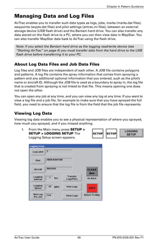
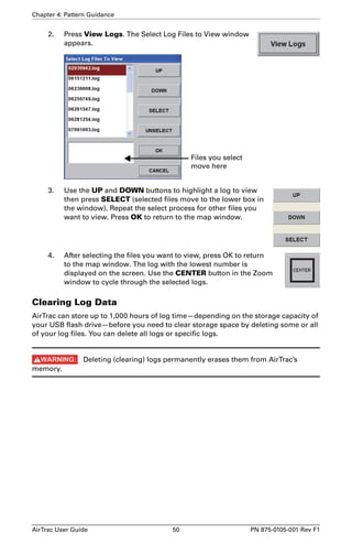
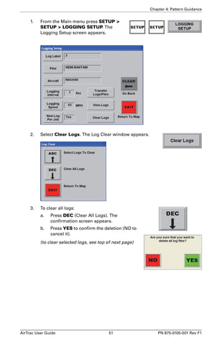
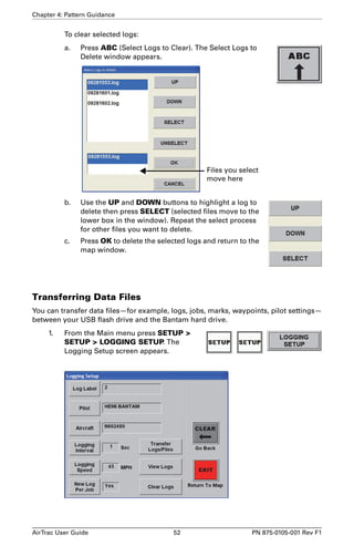
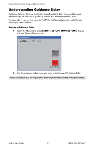
![Chapter 4: Pattern Guidance
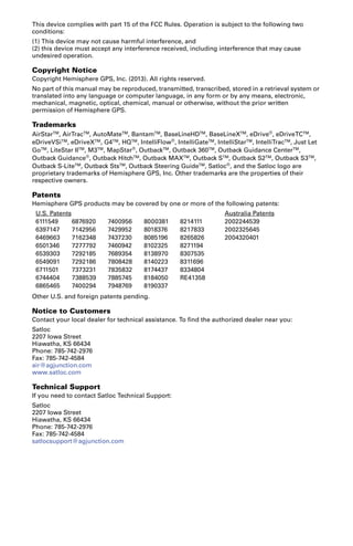
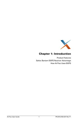
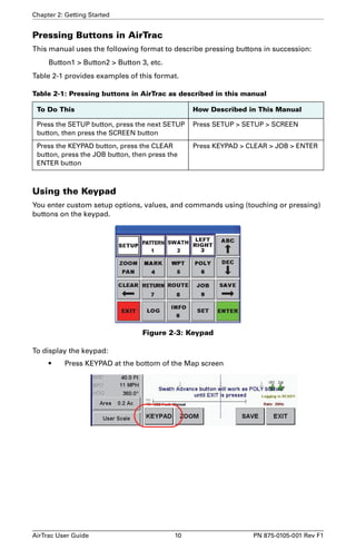
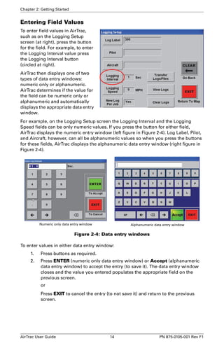
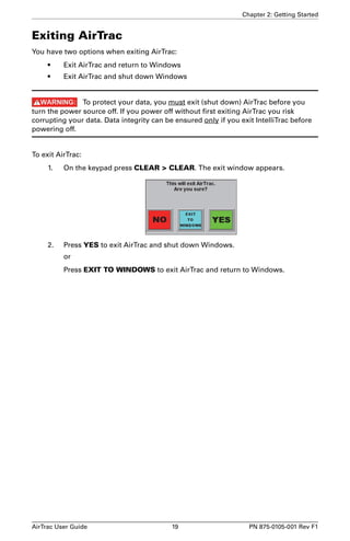
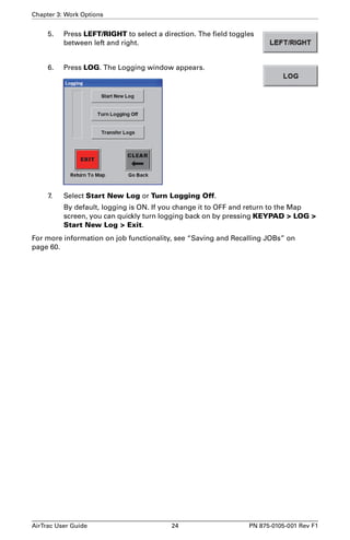
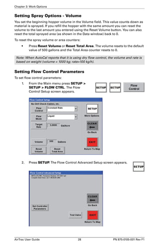
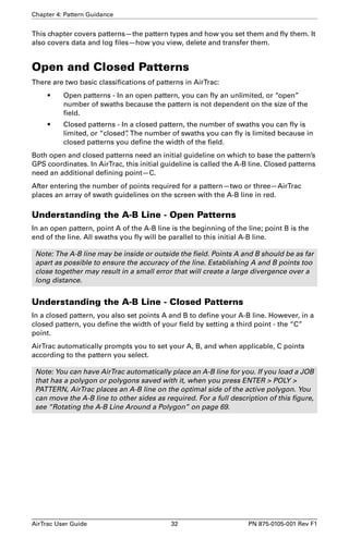
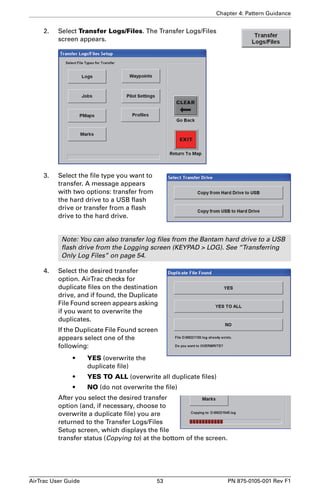
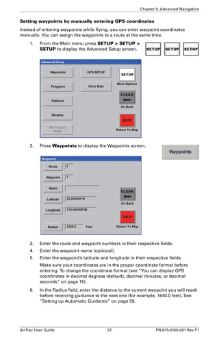
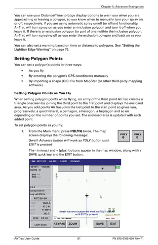
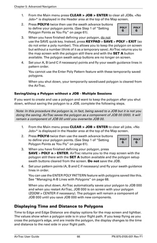
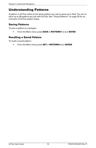
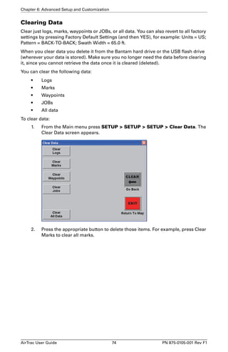
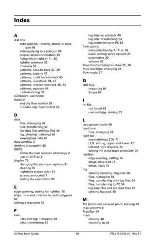
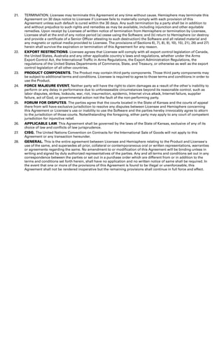
7. Make the turn onto your next swath using the lightbar for guidance.
E
b. Use lightbar guidance to find Swath #2
H
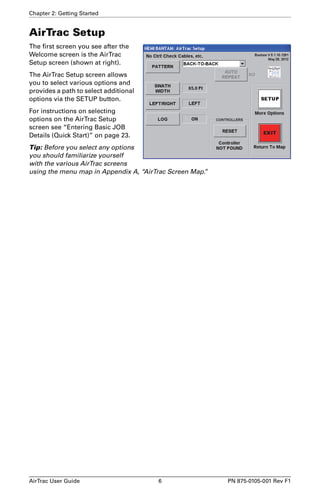
D
c. Turn on spray
F G
d. Fly Swath #2
D
E
F
e. Turn off spray
Lightbar guidance: the top row of LEDs
shows cross-track distance and direction to
target swath; the bottom row of LEDs shows
the heading (angle of intercept) to your target
swath. LEDs lined up in the center (c.) means
you are lined up on the swath.
a. Press Swath
Advance at
beginning of
turn
8. Turn the spray on as you enter the field.
9. Fly Swath #2 using lightbar guidance. The
top row of LEDs show you the distance
and direction (right or left) you need to fly
to get to the target swath line. The default
right display tells you the exact cross-track
distance.
The bottom row of LEDs tells you the
heading angle needed to intercept the
target swath line. The default left display
tells you the current swath number.
Cross-track distance
Heading angle
Swath line
Cross-track distance
Cross-track direction
(R [right] or L [left])
Swath
Heading angle
number
AirTrac User Guide 34 PN 875-0105-001 Rev F1](https://image.slidesharecdn.com/manualdelusuariobantam-141016053116-conversion-gate02/85/Manual-del-usuario-Satloc-bantam-41-320.jpg)
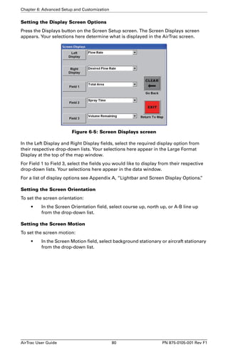
![Chapter 5: Advanced Navigation
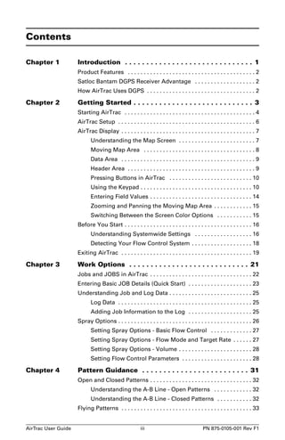
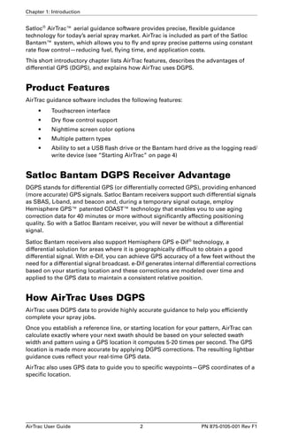
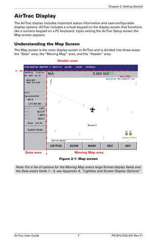
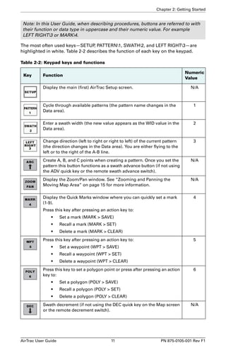
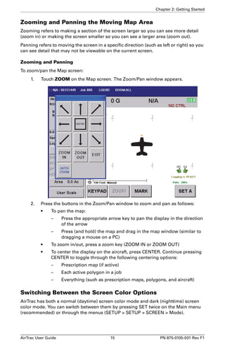
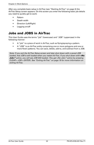
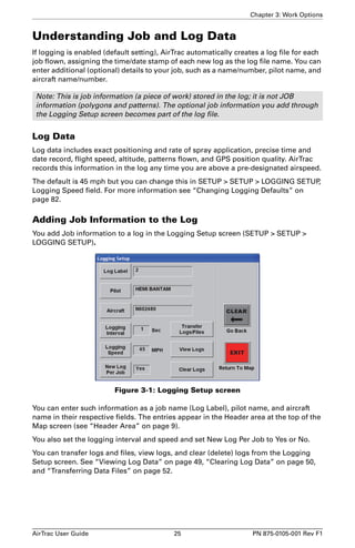
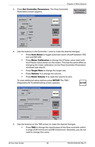
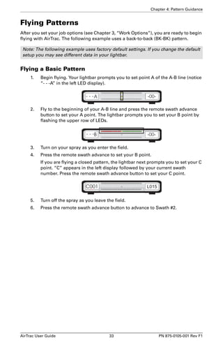
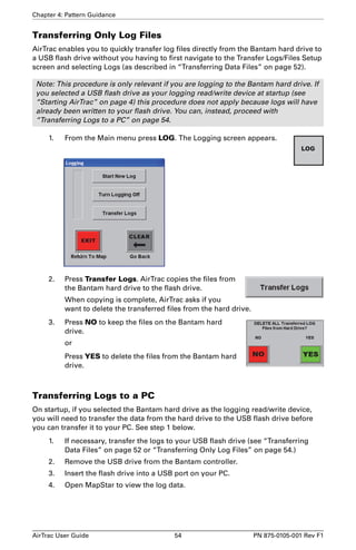
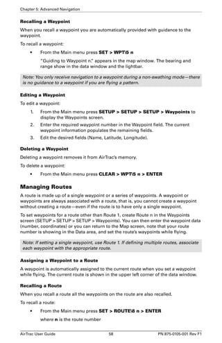
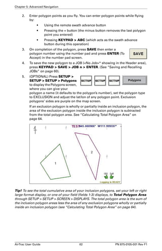
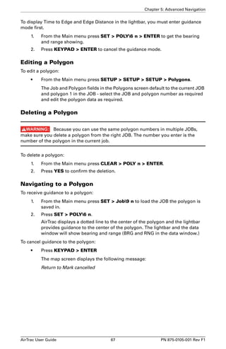
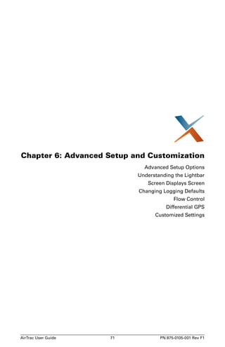
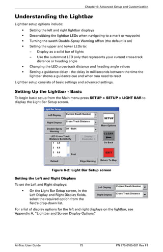
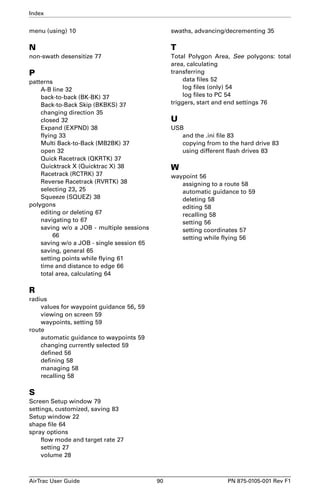
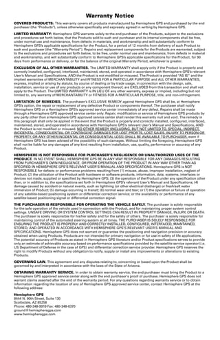
Entering GPS Coordinates Manually
To manually enter the GPS coordinates of the polygon:
1. From the Main menu press
SETUP SETUP SETUP
Polygons to display the
Polygons screen
2. Select the job and polygon number as required. The default job is the
currently active JOB (the JOB loaded on the map screen). The default
polygon number is 1.
3. Give the polygon a name as required. The name (“CRW I” in the example)
replaces the polygon’s number within the polygon in the map screen. The
information Poly # n [Area] at the top left of the Moving Map area retains the
polygon’s number (Poly # 1 below).
4. Set the polygon type to INCLUSION, EXCLUSION, or OPEN.
• Inclusion - the area of the polygon is included in the total polygon area
calculation.
• Exclusion - the area of the polygon is excluded from the total polygon
area calculation.
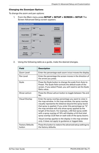
AirTrac User Guide 63 PN 875-0105-001 Rev F1](https://image.slidesharecdn.com/manualdelusuariobantam-141016053116-conversion-gate02/85/Manual-del-usuario-Satloc-bantam-70-320.jpg)
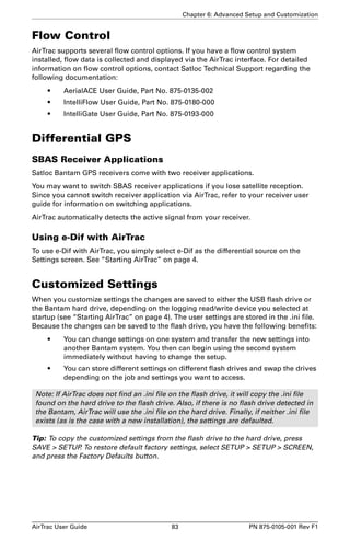
![Chapter 6: Advanced Setup and Customization
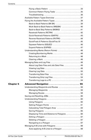
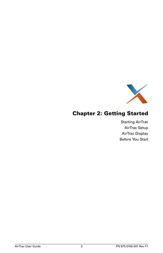
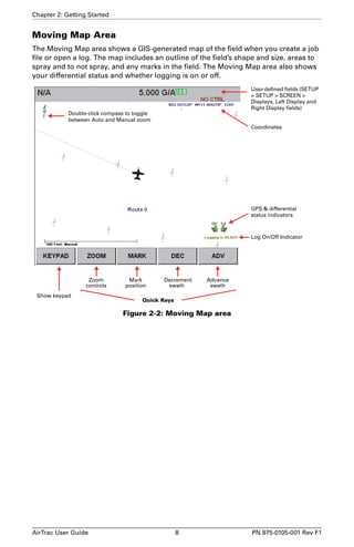
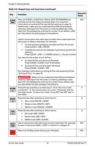
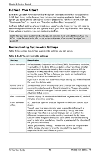
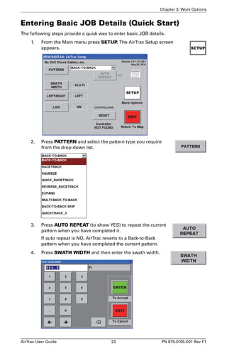
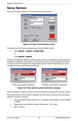
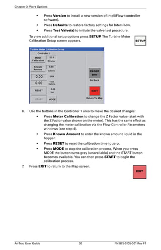
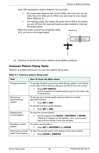
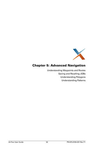
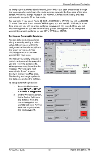
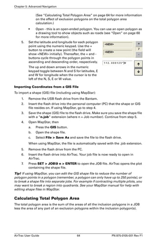
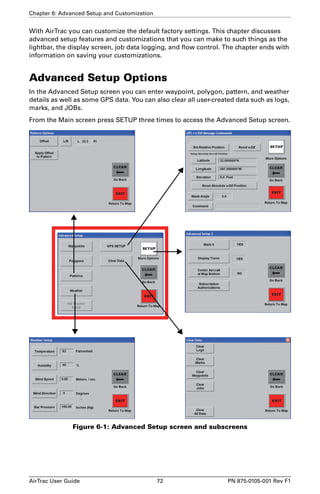
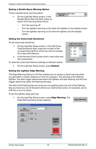
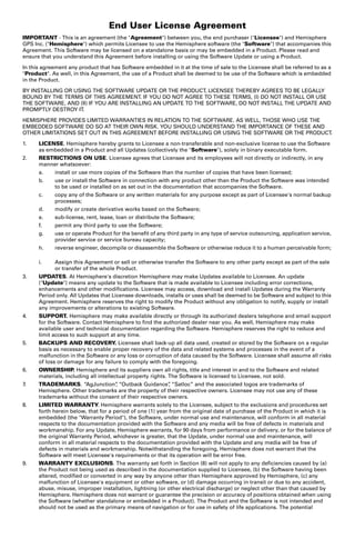
Screen Displays Screen
The Screen Displays screen setup options include:
• Setting the mode (Normal [daytime] colors or Dark [nighttime] colors)
• Setting the left and right display options (these correspond to the Large
Format Display Area on the display screen)
• Setting the display screen orientation (course up, north up, or A-B line up)
• Setting the display screen motion (background or aircraft stationary)
• Setting the display language
• Setting the zoom and pan options (advanced setup)
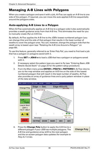
Setting Up the Display Screen
From the Main menu press SETUP SETUP SCREEN to display the Screen Setup
screen.
Figure 6-4: Screen Setup screen
Setting the Mode
In the Mode field, select Normal or Dark for daytime or nighttime screen colors,
respectively.
Tip! You can also switch between the daytime and nighttime colors by pressing SET
SET.
AirTrac User Guide 79 PN 875-0105-001 Rev F1](https://image.slidesharecdn.com/manualdelusuariobantam-141016053116-conversion-gate02/85/Manual-del-usuario-Satloc-bantam-86-320.jpg)
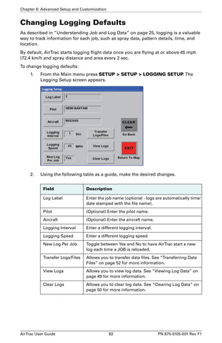


The Airtrac User Guide provides operational details for a DGPS receiver compliant with FCC Part 15 rules, emphasizing that it must avoid interference. It includes product features, setup instructions, navigation options, and troubleshooting guidelines, alongside a copyright notice and trademark information. For technical assistance, users can contact authorized dealers or Satloc's support services.


