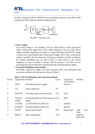
This document describes the KYL-200L low power wireless transceiver data module made by Shenzhen KYL Communication Equipment Co., Ltd. The KYL-200L has low power consumption, long transmission distances, and supports multiple connection methods and data formats. It can be used for applications like automatic meter reading, security systems, building automation, and wireless sensor networks. The document provides details on the module's specifications, antenna options, programming and setup instructions.
1. Shenzhen KYL Communication Equipment Co.,
Ltd
KYL-200L Low Power Wireless
Transceiver Data Module
Shenzhen KYL Communication Equipment Co., Ltd
Address: C3705-3707, Huangdu Square, South of Exhibition Center, Yitian Road,
Futian District, Shenzhen, Guangdong, China 518048
Tel: 86-755-82943662
Fax: 86-755-83408785
Skype: KYL-Sunny
Yahoo messenger: KYL_Sunny@yahoo.com
MSN: KYL-Sunny@hotmail.com
Email: sales02@rf-data.com
Website: http://www.rf-data.com
Fax: +86-755-83408785 sales02@rf-data.com www.rf-data.com 1
2. Shenzhen KYL Communication Equipment Co.,
Ltd
Catalogue
I. About KYL-200L ...........................................................................3
II. Features of KYL-200L .................................................................3
III. Applications of KYL-200L......................................................... 4
IV. How to Use KYL-200L..................................................................4
V. Network Application of KYL-200L............................................ 14
VI. Technical Specification of KYL-200L....................................... 14
VII. Description of Type................................................................... 15
Fax: +86-755-83408785 sales02@rf-data.com www.rf-data.com 2
3. Shenzhen KYL Communication Equipment Co.,
Ltd
Before using our products, please read the user manual carefully.
Any questions, please contact me at the above mentioned methods.
I: About KYL-200L
KYL-200L is a kind of low power wireless transceiver data module. With small size,
low power consumption as well as good stability and reliability, it is widely used as
wireless data transceiver in long-ranges, narrowband low power UHF wireless data
transmitters and receivers with channel spacing as low as 25 KHz.
II: Features of 200L
1. Low power transmission: 500mW (default), 600mW~1W (optional).
2. Carrier frequency: 433MHz (default), 400-470MHz, 868MHz, 915MHz
(optional)
3. High anti- interference and Low BER (Bit Error Rate)
Based on GFSK modulation, high-efficiency forward error correction channel
encoding technology is used to ensure the data’s resistance against both transient
interference and random interference. The actual BER can be achieved to 10-5~ 10-6
when channel BER is 10-2.
4. Long Transmission Distance
Within the visible range, when the height of antenna is higher than 2m and the BER
is 10-3, the reliable transmission distance is 3000m @1200bps and 2000m@9600bps
respectively.
5. Transparent data transmission
Transparent data interface used in transceivers is to satisfy many standard and
nonstandard user protocols. Any false data generated in air can be filtrated
automatically (What has been received is exactly what has been transmitted).
6. Multi-channels
KYL-200L provides 8 channels, expandable for 16, 32 channels according to
requirements of users.
7. 2 ports with three connection methods
KYL-200L transceivers provide 2 ports with three connections: a UART interface
of TTL level, a non-standard RS-232 port and a non-standard RS-485 port.
8. Big data buffer area
With optional interface baud rates: 1200/4800/9600/19200bps and 8N1/8E1/8O1
data format (decide by user), the transceiver can transmit unlimited data frames
with flexible user program.
Fax: +86-755-83408785 sales02@rf-data.com www.rf-data.com 3
4. Shenzhen KYL Communication Equipment Co.,
Ltd
Note: the RF data rate is only settled down before delivery; please specify our sales
your requirements when placing your orders.
9. Intelligent data control system and no other extra programs required
Even for half duplex communication, no other excessive programs are required.
All RF system data transmission/reception and other On-the-Fly conversion and
control are performed by KYL-200L transceivers automatically.
10. Lower power consumption & nice sleep function
With +5V power, the receiving current is less than 25mA, the transmitting current
is less than 300mA, and the sleeping current is less than 20uA.
11. High reliability, small size and excellent performance
By using monolithic radio-frequency integrated circuit and single-chip MCU, the
transceivers have less peripheral circuits, high reliability, and low failure rate.
12. Various options for configurable antennas.
13. Watchdog monitor inside
Watchdog monitors the inner operation, so it can change the traditional product
structure and also improve the reliability of our modules.
III: Application of KYL-200L:
KYL-200L is suitable for:
* Automatic Meter Reading (AMR);
* Wireless alarm and security systems;
* Building automation, security systems, wireless monitor, remote control and
access control system;
* Wireless data transmission, automatic data collection system;
* Radio modem can be used for Sports training & competition;
* Wireless dishes ordering;
* Wireless POS, PDA wireless smart terminal;
* RF module can be used for electronic bus station and intelligent traffics;
* RF transmitter, Wireless electronic display screen and Queuing machine;
* Wireless telemetry; charging for parking, parking lot;
* Wireless modem automobile inspection and four-wheel orientation;
* Wireless sensor, Industrial wireless remote control and air conditioning remote
controller;
* Data communication in the aspects of railway, oil field, dock and army.
* LED display in thruway and public place;
* Point to multi-point wireless network, wireless on-the-spot bus and automatic
data collection system
IV: How to use the KYL-200L
KYL-200L provide RS-232, RS-485 and UART/TTL level interface ports which can
Fax: +86-755-83408785 sales02@rf-data.com www.rf-data.com 4
5. Shenzhen KYL Communication Equipment Co.,
Ltd
be direct connected with PC, RS485 devices, monolithic processors and other UART
components. Please find the schematic diagram below:
1. Power supply
The factory setting is +5V (needing 7.5V-12V, please notify us when placing the
order). Using better ripple factor, KYL-200L transceivers can also share power
supply with other equipment. If possible, a voltage-stabilizing chip with 5V voltage
is much more recommended than Switch power supply. But if only switch power
supply is available, the jam caused by switch pulse should be avoided. In addition,
the reliable grounding must be used if there is other device in the system
equipment. In case of failing to connect with the ground, it can form its own
grounding but must be absolutely separated from the municipal electric supply.
2. Connection Definition with terminal
KYL-200L transceivers supply one 9-pin connector (JP1), their definitions and
connection methods with terminals are shown in Table 1.
Table 1: JP1 Pin Definitions and connection methods
Pin No. Signal Name Function Level Connection Remarks
with terminal
1 GND Grounding of power supply Ground
2 Vcc Power supply DC 5V
3 RxD/TTL Serial data input to the transceiver TTL TxD
4 TxD/TTL Transmitted data out of the transceiver TTL RxD
5 SGND Signal
6 A (TXD) A of RS-485(TxD of RS-232) A(RxD)
7 B (RXD) B of RS-485(RxD of RS-232) B(TxD)
8 SLEEP Sleep control (input) TTL Sleep signal High level
sleep
9 RESET Reset signal(input) TTL Negative
pulse reset
Fax: +86-755-83408785 sales02@rf-data.com www.rf-data.com 5
6. Shenzhen KYL Communication Equipment Co.,
Ltd
3. The connection schematic diagram between computer and our RF module
4. Setting of channel, interface, and data format
Before using KYL-200L, the user needs to make simple configuration to
determine the channel, interface mode and data format based on his own needs.
You can view or change the module's interface baud rate, channel and address
code, parameter setting or reading as per the testing software KYLCOM in the PC
(in products box). And the configuration is as follows:
i. Channel configuration:
Channel No. Frequency Channel No. Frequency
1 429.0325MHZ 5 433.0325MHZ
2 430.0325MHZ 6 434.0325MHZ
3 431.0325MHZ 7 435.0325MHZ
4 432.0325MHZ 8 436.0325MHZ
Note: the frequency points corresponding to each channel can be adjusted
based on the user’s needs.
ii. The schematic diagram of setting the parameter is in the following:
a. Connect PC and the module with RS232 data cable.
b. Open “KYLCOM” PC software, and then select “English”:
Fax: +86-755-83408785 sales02@rf-data.com www.rf-data.com 6
7. Shenzhen KYL Communication Equipment Co.,
Ltd
ⅲ. Click “open port”, a small window as following will appear. You can write the
parameters in the columns.
ⅳ Click “read paras”.
“Read correct” shows your connection between KYL module and PC is correct.
Fax: +86-755-83408785 sales02@rf-data.com www.rf-data.com 7
8. Shenzhen KYL Communication Equipment Co.,
Ltd
If you want to change some technical parameters, you need to do as follows.
ⅴ. Change the parameters like channel, interface rate and parity mode through the
button on the left window. After writing the parameters in the left catalogue, click
“write para”, then “write correct” showed. So you have finished the process of
changing technical parameter.
Fax: +86-755-83408785 sales02@rf-data.com www.rf-data.com 8
9. Shenzhen KYL Communication Equipment Co.,
Ltd
Note: The RF data rate (Air Rate) can not be set by the user. It is fixed before
delivery. So please specify the RF data rate when placing the order.
Fax: +86-755-83408785 sales02@rf-data.com www.rf-data.com 9
10. Shenzhen KYL Communication Equipment Co.,
Ltd
5. Installation dimension:
6. The Function-indicator light
a. The LED indicator light will turn red for 0.5S once switch on.
b. The LED indicator light will turn green continually while receiving data from air.
c. The LED indicator light will turn red continually when transmitting data into air
after receiving from COM.
d. If the module keeps sleep function, LED indicator light is always dark.
7. Supported protocol and Transmit capability
KYL-200L standard transceivers offer transparent protocol to support various
applications and protocols of users. If you need to decrease his cost or ease the
workload of terminal CPU, we can add other specific functions based on the
transparent protocol, such as addressing, data acquisition, command interpretation,
etc.
8. Sleep function
In order to reduce consumption, KYL-200L transceivers support sleep function. In
sleep mode, the current consumption is less than 20uA.
a. How to use sleep function:
The Pin8 ‘SLP’ in JP1 is the signal of sleep control. At high power level,
transceiver stays in working mode. At low power level (<0.5V), transceiver stays
in sleep mode. The SLP signal can convert transceiver from working to sleep
mode in 1ms after falling edge. If the Sleep signal arrives when the transceiver is
transmitting data, the module will move to sleep mode after finishing
transmission. From sleep moves to working, it takes the transceiver 1ms after
rising edge.
To disable the opened sleep function of KYL-200L, the SLP (SLEEP) pin should
Fax: +86-755-83408785 sales02@rf-data.com www.rf-data.com 10
11. Shenzhen KYL Communication Equipment Co.,
Ltd
be definitely connected with 0 or ground.
b. Attentions about using sleep function:
When the sleep function enabled, or any supply glitches, such as switch
dithering, fire striking or quick switching on and off, may cause the transceiver
switch to wrong sleep mode.
After switching on, users can avoid this error by making a compulsive restoration
once after the CPU delays 100ms.
Sleep Timing Diagram:
9. Attentions about data transmission
a. The delay time (tc) of conversion between transmitting and receiving is less
than 1ms.
Timing diagram:
b. The delay time of transceivers between the first bit sent by TxD to the first
bit received by RxD.
As data processing will be made on user’s data by KYL-200L transceiver using
FEC (Forward Error Correction) or other correction algorithm, when RxD of a
Fax: +86-755-83408785 sales02@rf-data.com www.rf-data.com 11
12. Shenzhen KYL Communication Equipment Co.,
Ltd
KYL-200L transceiver ‘A’ receives the data, then transmits it, the other one
transceiver ‘B’ will have a delay (ts) to receive and transmit by TxD. Different
RF data rate causes different delay time. Please see the specific delay time
below:
RF Date Rate Delay RF Date Rate Delay
(bps) Ts(mS) (bps) Ts(mS)
1200 90 9600 16
2400 48 19200 10
4800 30
Timing diagram:
c. Error dealing procedure:
To enhance the reliability and stability of user’s systems, a verify bit or a Cyclic
Redundancy Check (CRC) mode is highly recommended to prevent wrong
information while using KYL-200L modules.
d. Large-number data transmission
In theory, when the interface data rate is faster than the RF data rate, KYL-200L
transceivers can sent unlimited-long data package, but long packages more than
120B are not recommended. The length of each package should be between
60~100B. We also recommend our users to use Automatic Error Request
Equipment (ARQ) to prevent wrong information.
Reasons:
What if the actual transmission BER (Bit Error Rate) is 10-4, 1 packet with 1KB
data which is about 10-thousand bits, is sent, theoretically, at least 1 bit will be
received wrongly, then the 1KB information will never be received correctly.
But if we package the data into 10 packets with 100B for each, when all 10
Fax: +86-755-83408785 sales02@rf-data.com www.rf-data.com 12
13. Shenzhen KYL Communication Equipment Co.,
Ltd
packets are sent, there will be only 1 packet wrong according to this probability.
After that, resend this wrong packet using ARQ mode. So by resending one more
packet and the efficiency rate is reduced 10%, all data will be absolutely received
correctly.
10. Antenna configuration:
Many appropriative antennas for low power RF modules are selected to meet
different users’ antenna configurations. Please ask our Sales for more information
about the antenna’s dimension and performance.
a. Helical SMA antennas
KYL-ANT-433-10-SMA: 100mm helical SMA antennas with high gain and low
cost, reach a long distance.
KYL-ANT-433-3-SMA: 28mm SMA helical antenna with magnetic core, small
size, beautiful appearance (like the mobile phone antenna)
KYL-ANT-433-10-ZSMA: 100mm SMA helical antenna with folding joint, easy
for adjusting the direction and fixing.
b. Magnetic vehicle antenna
KYL-ANT-O433S-300H1.5-SMA: include magnetic antenna base, suitable for
equipment with metal shell, easy for fixing, effective to enhance the transmission
distance.
Fax: +86-755-83408785 sales02@rf-data.com www.rf-data.com 13
14. Shenzhen KYL Communication Equipment Co.,
Ltd
For more kinds of antennas , please go to our website: http://www.rf-
data.com/Products_list_en.asp?classid=163
If you have special requirements on antennas, we can design and produce for you
individually.
V. Network Application of KYL-200L
The communication channel of KYL-200L is half duplex, which is most suitable
for the communication mode of point to multi-point. Under this mode, one
master station must be set, and all of the rest are slave stations. A unique address
is given to each station. The coordination of communication is controlled by
master station that uses data frames containing address code to transmit data or
command. Slave station will receive all of the data and command and compare
the received address code with local address code. If they are different, the data
will be deserted without any response. If those address codes are the same, it
means the data is sent to the local. Slave station will make different responses
according to the transmitted data or command and send back the data of
response. All these jobs must be performed by upper protocol, and it is assured
that there is only one transmitter-receiver in the state of transmission in the
communication network at any instant moment so as to avoid the cross-
interference.
KYL-200L can also be used for point-to-point communication with easier
operation. For the programming of serial port, all you have to do is to remember
that its communication mode is semi duplex while always observing the time
sequence of come-and-go for receiving and transmitting.
VI. Technical specification of KYL-200L
* Modulation mode: GFSK/FSK
* Working frequency: 400MHz~470MHz, 868MHz, 915MHz;
* Power supply: DC 5V (7.5V~12V, please specify when placing the order);
* RF power: ≤500mW, 600mW~1W is available;
* RF data rate: 1200/2400/4800/9600/19200bps (Set before delivery);
* Receive current: <25mA (TTL connect);
* Receive sensitivity: -120dBm (1200bps); -115dBm (9600bps);
* Transmitting current: <300mA;
* Sleep current: <20uA;
* Interface data format: 8E1/8N1/8O1;
* Working humidity: 10%~90% relative humidity without condensation;
* Working temperature: -35℃~+75℃ (industrial)
* RF Line-of-sight Range: 2000m (BER=10-5@9600bps);
Fax: +86-755-83408785 sales02@rf-data.com www.rf-data.com 14
15. Shenzhen KYL Communication Equipment Co.,
Ltd
3000m (BER=10-5@1200bps);
* Size: 53mm*38mm*10mm (without antenna port).
VII. Description of type
Baud Rate
12:1200bps
KYL-200L-96
Manufacturer
Type 24:2400bps
48:4800bps
96:9600bps
192:19200bps
Fax: +86-755-83408785 sales02@rf-data.com www.rf-data.com 15