Manas Brochure - Wafer Type Flow Meter.pdf
•
0 likes•5 views

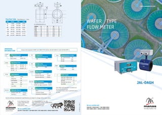
Water is the most vital utility in any industry, hence Manas has produced an affordable variety of electromagnetic flowmeters for accurate water flow measurement. Wafer Style electromagnetic Flow Meter, called Jal-Oagh provides the solution to knowing your water use, not only by guesswork but by proper instrumentation with economy and fairly good accuracy. Sizes available for Wafer Type are DN 50 to DN 200
![ERROR DIAGRAM
PRINCIPAL ADVANTAGES
PRINCIPLE OF OPERATION
INTRODUCTION
Know your water consumption
Not just by assumption
But by correct instrumentation
Jal-Oagh provides the solution
MANAS has introduced a new economical
series of E.M.F., considering water as the most
important utility in any industry.
APPLICATIONS
JAL-OAGH,
300 SERIES OF EMF
These flow meters are dedicated to waste
water management system, sewage and
effluent water measurement. Wafer is
available from DN 50 to DN 200
i.e. Jal-Oagh 300 Series.
Small in size, Light in weight compared to other
magnetic meters in its class
Full-bore electromagnetic flow meter with absolutely
no restriction to flow
The JAL-OAGH series of electromagnetic flow meters work on
FARADAY'S LAW OF ELECTROMAGNETIC INDUCTION. When a
conductor moves within a magnetic field, voltage is induced in
it which is proportional to the velocity of the conductor.
In this case, the conductor is flowing media.
The equation is as below:
E = B.v.D
Where
E = Induced voltage [proportional to velocity]
B = Magnetic flux density
v = Mean velocity of the media
d = distance between the sensing electrodes
For a given size of flow tube & and compatible amplifier the
flux density 'B' is constant, and the distance between the
electrodes is constant. Hence, the induced voltage is
proportional to the velocity of the flowing media. Thus the unit
can be calibrated in terms of volumetric flow rate by knowing
the cross-sectional area of the tube.
Has a typical accuracy of ±0.5%
Measurement is independent of the velocity profile
across the pipe
Measurement results are independent of density,
viscosity, pressure, temperature, solid impurities, and
conductivity variations (above 5 µS/cm for MFT-01 and
above 20 µS/cm for (SJ-1102)
Fits in between the flanges of the pipe which makes it
the most compact solution for flow measurement
Compatible virtually with all corrosive and non-corrosive
liquids
It is a very cost-effective and economical flow meter as
compared to other flow meters in its class
Effluent Treatment: Untreated as well as Treated
Effluent Water Measurement
Sewage Treatment: Wastewater measurement, Sludge
measurement, etc.
Water Supply Schemes: Raw water as well as treated
water measurement
Boiler Feed Water Measurement
Chemical Industries: Measurement of acidic and alkaline
chemicals and slurries
Input
Ranges
Accuracy
Mounting
Ingress
Protection
Meter Size
Min Media
Conductivity
Operating
Temperature
Operating
Temperature
Media :
Temperature
Repeatability
End
Connections
Material of
Construction
Local Display
Flow Velocity
Range
Signal Output
Metering tube :
Media Pressure :
: IP68
: 0-50 °C
: 0-50 °C
Power Supply : Pulsed D.C.
to field coils
: 0. 2% of reading
: 0.1 m/s to 10 m/s
: Greater than 5 µS/cm
: DN 50-DN 200 (Wafer)
Rubber Liner 0 - 90 °C max
PTFE Liner 0 - 150 °C max
: Integral / Remote Mounting
4 fixed ranges I) 1.25 ii) 2.50
iii) 5.00 iv) 10.00 m/s FS
Upto DN80 - PN40
From DN100 - DN150 - PN16
DN200 - PN10
Micro-volt Signal proportional to
flow rate from primary Flow sensor
Wafer: DN 50 - DN 200 Meter to be
sandwiched between Two ANSI150
class Flanges
Maximum Inaccuracy 1% of reading
between 100% to 10% of calibrated
flow range
Jal-oagh 301(Wafer-Rubber)
Jal-oagh 302 (Wafer- PTFE)
Jal-oagh 303 (Wafer-Rubber-SMART)
Jal-oagh 304 (Wafer-PTFE-SMART)
a) Flow Tube: SS 304 (non-magnetic)
b) Electrodes: SS 316, Hastelloy'C
c) Liner: Ebonite, PTFE
d) Body material: SS 304
i) 3½ digit, 0.5” LCD calibrated in % or
engineering units
ii) 8 digit LCD non-resettable type for
totalized quantity
i)4-20mA DC isolated in max 600 prop.
to 0-100% of flow rate
ii) Pulsed output with adjustable count
rate from 1 count/Hr to 105 counts/ Hr
(Open collector with 30 mA/ 24 V DC
capacity ). (Optional)
Input
Ranges
Accuracy
Mounting
Keyboard
Ingress
Protection
Material of
Housing
Material of
Housing
Min Media
Conductivity
Operating
Temperature
Repeatability
Flow Velocity
Range
Temperature
Drift
Cable Entries
Cable Entries
Local Display
COMM PORT
(Optional)
Power Supply
Power Supply
: IP67
Ingress Protection : IP67
: 0- 50 °C
: Al Die cast
: Al Die Cast
: 0.015% per °C
Temperature Drift : 0.015% per °C
: 0. 2% of reading
0.3 m/s to 10 m/s
: Greater than 20µS/cm
: 230VAC/ 110VAC, 50 Hz
RS232 / RS485
(Protocol MODBUS RTU)
4 nos for remote transmitter
2 nos for integral transmitter
PG 11/ ½” NPT/ ½” BSP
4 nos for remote transmitter
2 nos for integral transmitter
PG 11
: 85 V AC to 265 V AC, 50 HZ
4 fixed ranges I) 1.25 ii) 2.50
iii) 5.00 iv) 10.00 m/s FS
4 Number of Keys for Parameter
Programming
Integral / Remote Mounting - Wall
Mounting / 2” Pipe Mounting
Maximum Inaccuracy 1% of reading
between 100% to 10% of calibrated
flow range
16 characters x 2 rows LCD Display
for Instantaneous Flow Rate, Totaliser,
Engineering Units, Fault messages
Micro-volt signal prop. to flow rate
1.
from Primary flow sensor
2. Empty Tube signal from primary
flow sensor
3. Signal Output (Optional) :
i) 4- 20 mA dc( Isolated ) in max. 600
Ohms prop. to 0 -100 % flow rate.
ii) Pulsed output with adjustable count
rate from 1 count/Hr to 105 counts/ Hr
(Open collector with 30 mA/ 24 V DC
capacity).(Optional)
JAL-OAGH
JAL-OAGH MFT- 01
SPECIFICATIONS
PRIMARY FLOW TUBE : JAL-OAGH
SMART JAL-OAGH (SJ-1102)
:
:
:
:
:
:
:
:
:
:
:
:
:
:
:
:
:](data:image/gif;base64,R0lGODlhAQABAIAAAAAAAP///yH5BAEAAAAALAAAAAABAAEAAAIBRAA7)
Recommended
Recommended
More Related Content
Similar to Manas Brochure - Wafer Type Flow Meter.pdf
Similar to Manas Brochure - Wafer Type Flow Meter.pdf (20)
More from ManasMicrosystems
More from ManasMicrosystems (20)
Recently uploaded
Recently uploaded (20)
Manas Brochure - Wafer Type Flow Meter.pdf
- 1. Tel: 8484039026 Ext. No. 106 Mob: +91 77220 34924 / 74200 99054 mktg@manasmicro.com www.manasmicro.com Power Supply Note: Wafer Style flowmeter is available from line size DN 50 to DN 200. *This Power Supply option is applicable only to SJ-1102 DN 50 65 80 100 125 150 200 m3/hr 7.068 11.945 18.095 28.274 44.178 63.617 113.097 LPM 117.809 199.098 301.592 471.238 736.310 1060.287 1884.955 LPS 1.963 3.318 5.026 7.853 12.271 17.671 31.415 EL 54, Electronic Zone, J-block, MIDC Bhosari, Pune 411026. Maharashtra, India. Due to continuous development specications are subject to change without prior notice. We are certified with: We are certified with ISO/IEC 17025:2017 | ISO 9001:2015 ISO 14001:2015 | OHSAS 45001:2018 ISO/IEC 17025:2017 | ISO 9001:2015 | ISO 14001:2015 | OHSAS 45001:2018 microsystems private limited Fc-OFM-02_1 | DPF-1 JAL-OAGH WAFER TYPE FLOW METER Flow Rate Table www.manasmicro.com Flow Rate at v - 1m/s Sample code explained: SMART JAL-DN65-PTFE-SS316L-NA-NA-SS304-SJ 1102-2D-RS4-RMT-U ALLDIMENSIONSAREINmm. ORDERING INFORMATION SJ1102 Mag Flow Transmitter SMART Jal-oagh Transmitter Flow Transmitter : MFT01 : SJ1102 Blind Indication Display Indication & Totalization : B : 1 D : 2 D Flow Transmitter Type 2D No Communication : NA RS 232 : RS2 RS 485 : RS4 Communication Facility RS4 SMART JAL : JAL : SMART JAL Wafer Wafer SMART Flow Sensor Type NA Flange/End Connection Standards NA : NA NA Flange / End Connection Material NA : NA SS316L : SS316L : HAST'C Electrode Material Stainless Steel 316 Hastelloy C PTFE Liner Material PTFE : PTFE Neoprene : NE Soft Rubber : SR Hard Rubber : HR PFA : PFA Any Other : ZZ Flow Sensor Size DN65 : 2" : 2 ½" : 3" : 4" DN 50 DN 65 DN 80 DN 100 DN 125 : 5" DN 150 : 6" DN 200 : 8" Carbon Steel Stainless Steel 304 Stainless Steel 316 Body Material : CS : SS304 : SS316 SS304 Mounting : INT : RMT Integral Remote Wall RMT 110 V AC ± 10%, 50 Hz : 1 230 V AC ± 10%, 50 Hz : 2 24 V DC : 3 *85-265 V AC, 50 Hz : U Any Other : Z U Power supply
- 2. ERROR DIAGRAM PRINCIPAL ADVANTAGES PRINCIPLE OF OPERATION INTRODUCTION Know your water consumption Not just by assumption But by correct instrumentation Jal-Oagh provides the solution MANAS has introduced a new economical series of E.M.F., considering water as the most important utility in any industry. APPLICATIONS JAL-OAGH, 300 SERIES OF EMF These flow meters are dedicated to waste water management system, sewage and effluent water measurement. Wafer is available from DN 50 to DN 200 i.e. Jal-Oagh 300 Series. Small in size, Light in weight compared to other magnetic meters in its class Full-bore electromagnetic flow meter with absolutely no restriction to flow The JAL-OAGH series of electromagnetic flow meters work on FARADAY'S LAW OF ELECTROMAGNETIC INDUCTION. When a conductor moves within a magnetic field, voltage is induced in it which is proportional to the velocity of the conductor. In this case, the conductor is flowing media. The equation is as below: E = B.v.D Where E = Induced voltage [proportional to velocity] B = Magnetic flux density v = Mean velocity of the media d = distance between the sensing electrodes For a given size of flow tube & and compatible amplifier the flux density 'B' is constant, and the distance between the electrodes is constant. Hence, the induced voltage is proportional to the velocity of the flowing media. Thus the unit can be calibrated in terms of volumetric flow rate by knowing the cross-sectional area of the tube. Has a typical accuracy of ±0.5% Measurement is independent of the velocity profile across the pipe Measurement results are independent of density, viscosity, pressure, temperature, solid impurities, and conductivity variations (above 5 µS/cm for MFT-01 and above 20 µS/cm for (SJ-1102) Fits in between the flanges of the pipe which makes it the most compact solution for flow measurement Compatible virtually with all corrosive and non-corrosive liquids It is a very cost-effective and economical flow meter as compared to other flow meters in its class Effluent Treatment: Untreated as well as Treated Effluent Water Measurement Sewage Treatment: Wastewater measurement, Sludge measurement, etc. Water Supply Schemes: Raw water as well as treated water measurement Boiler Feed Water Measurement Chemical Industries: Measurement of acidic and alkaline chemicals and slurries Input Ranges Accuracy Mounting Ingress Protection Meter Size Min Media Conductivity Operating Temperature Operating Temperature Media : Temperature Repeatability End Connections Material of Construction Local Display Flow Velocity Range Signal Output Metering tube : Media Pressure : : IP68 : 0-50 °C : 0-50 °C Power Supply : Pulsed D.C. to field coils : 0. 2% of reading : 0.1 m/s to 10 m/s : Greater than 5 µS/cm : DN 50-DN 200 (Wafer) Rubber Liner 0 - 90 °C max PTFE Liner 0 - 150 °C max : Integral / Remote Mounting 4 fixed ranges I) 1.25 ii) 2.50 iii) 5.00 iv) 10.00 m/s FS Upto DN80 - PN40 From DN100 - DN150 - PN16 DN200 - PN10 Micro-volt Signal proportional to flow rate from primary Flow sensor Wafer: DN 50 - DN 200 Meter to be sandwiched between Two ANSI150 class Flanges Maximum Inaccuracy 1% of reading between 100% to 10% of calibrated flow range Jal-oagh 301(Wafer-Rubber) Jal-oagh 302 (Wafer- PTFE) Jal-oagh 303 (Wafer-Rubber-SMART) Jal-oagh 304 (Wafer-PTFE-SMART) a) Flow Tube: SS 304 (non-magnetic) b) Electrodes: SS 316, Hastelloy'C c) Liner: Ebonite, PTFE d) Body material: SS 304 i) 3½ digit, 0.5” LCD calibrated in % or engineering units ii) 8 digit LCD non-resettable type for totalized quantity i)4-20mA DC isolated in max 600 prop. to 0-100% of flow rate ii) Pulsed output with adjustable count rate from 1 count/Hr to 105 counts/ Hr (Open collector with 30 mA/ 24 V DC capacity ). (Optional) Input Ranges Accuracy Mounting Keyboard Ingress Protection Material of Housing Material of Housing Min Media Conductivity Operating Temperature Repeatability Flow Velocity Range Temperature Drift Cable Entries Cable Entries Local Display COMM PORT (Optional) Power Supply Power Supply : IP67 Ingress Protection : IP67 : 0- 50 °C : Al Die cast : Al Die Cast : 0.015% per °C Temperature Drift : 0.015% per °C : 0. 2% of reading 0.3 m/s to 10 m/s : Greater than 20µS/cm : 230VAC/ 110VAC, 50 Hz RS232 / RS485 (Protocol MODBUS RTU) 4 nos for remote transmitter 2 nos for integral transmitter PG 11/ ½” NPT/ ½” BSP 4 nos for remote transmitter 2 nos for integral transmitter PG 11 : 85 V AC to 265 V AC, 50 HZ 4 fixed ranges I) 1.25 ii) 2.50 iii) 5.00 iv) 10.00 m/s FS 4 Number of Keys for Parameter Programming Integral / Remote Mounting - Wall Mounting / 2” Pipe Mounting Maximum Inaccuracy 1% of reading between 100% to 10% of calibrated flow range 16 characters x 2 rows LCD Display for Instantaneous Flow Rate, Totaliser, Engineering Units, Fault messages Micro-volt signal prop. to flow rate 1. from Primary flow sensor 2. Empty Tube signal from primary flow sensor 3. Signal Output (Optional) : i) 4- 20 mA dc( Isolated ) in max. 600 Ohms prop. to 0 -100 % flow rate. ii) Pulsed output with adjustable count rate from 1 count/Hr to 105 counts/ Hr (Open collector with 30 mA/ 24 V DC capacity).(Optional) JAL-OAGH JAL-OAGH MFT- 01 SPECIFICATIONS PRIMARY FLOW TUBE : JAL-OAGH SMART JAL-OAGH (SJ-1102) : : : : : : : : : : : : : : : : :