Download to read offline

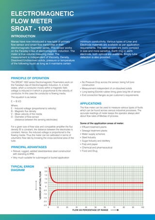
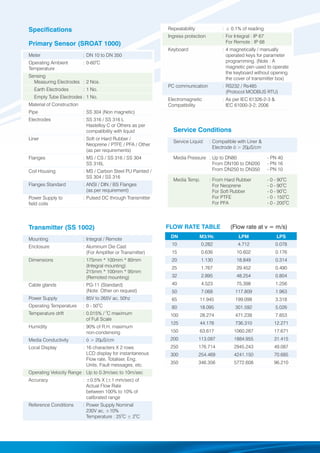
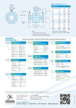

The document provides detailed specifications for the Sroat 1002 series electromagnetic flowmeter, which utilizes Faraday’s law of electromagnetic induction for accurate flow measurement of various fluids. The meter is designed for robust performance in industrial applications and is certified with multiple quality standards including ISO/IEC 17025:2017. Key features include its independence from liquid properties like viscosity and density, empty tube detection, and a variety of customizable options for materials and configurations.


