Download to read offline
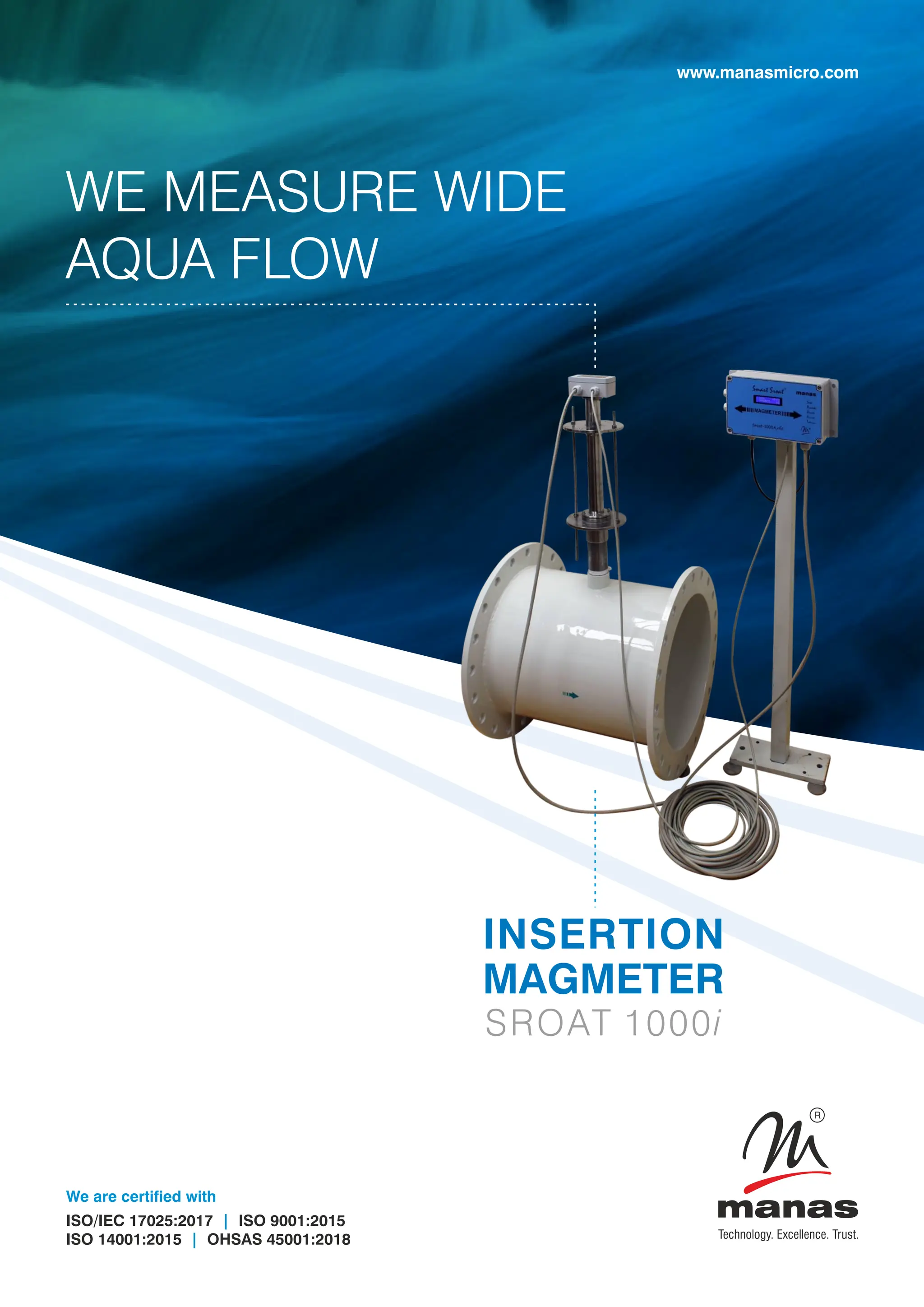


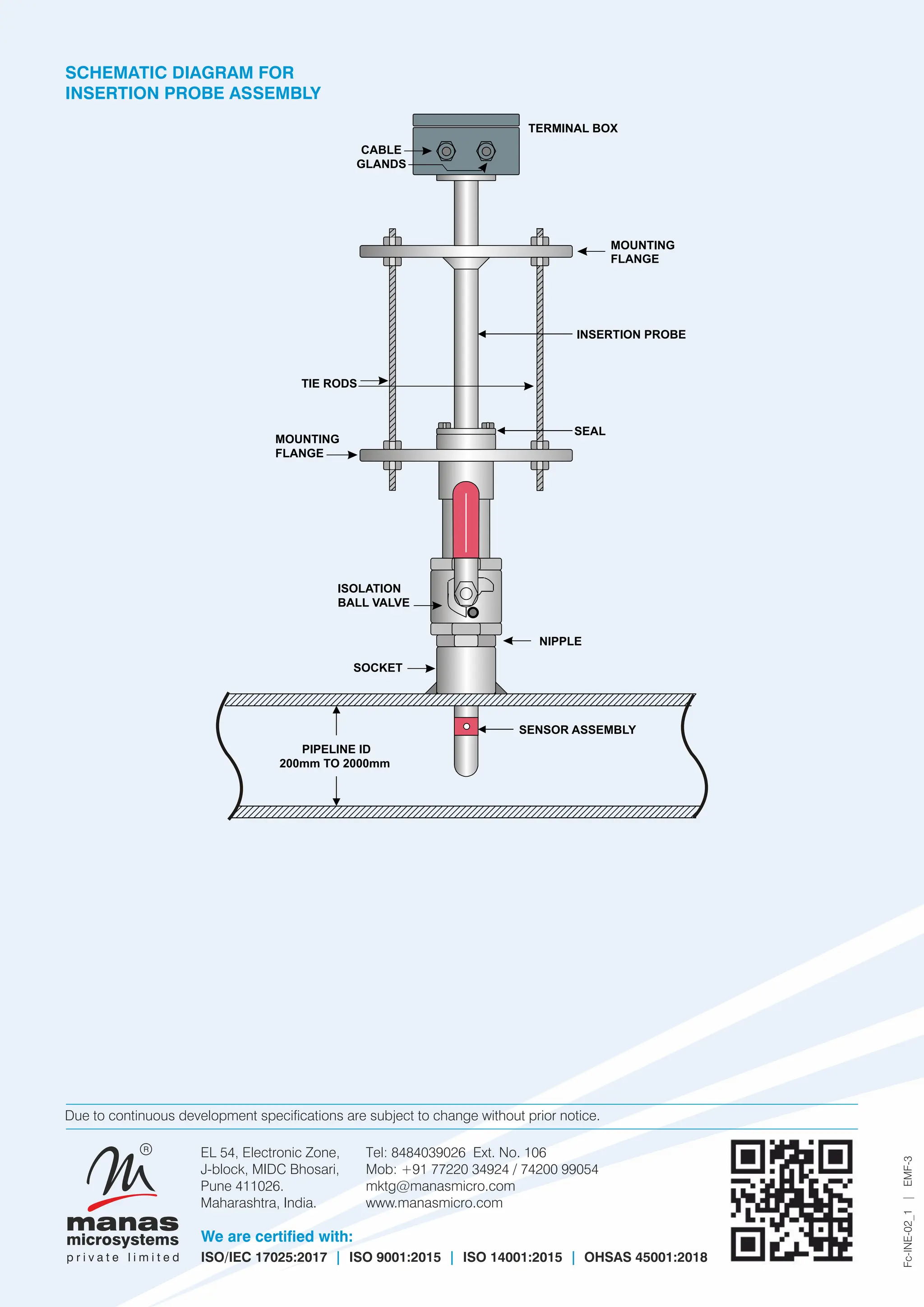

The document discusses the Sroat 1000i insertion type electromagnetic flow meter by Manas Microsystems, which is designed for measuring water flow in large diameter pipes with an accuracy of ±1%. It operates based on Faraday's law of electromagnetic induction and provides a standard current output of 4-20 mA DC, with advantages such as excellent long-term stability and compatibility with various liquids. The flow meter is applicable in multiple industries, including water supply, effluent treatment, and pharmaceuticals, and is certified to several international quality standards.


