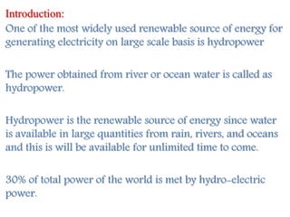
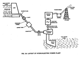
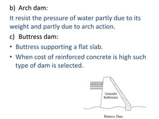
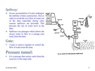
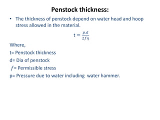
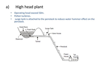
Topics:
1. Types of Gravity Dam
2. Forces Acting on a Gravity Dam
3. Causes of failure of Gravity Dam
4. Elementary Profile of Gravity Dam
5. Practical Profile of Gravity Dam
6. Limiting height of Gravity Dam
7. Drainage and Inspection Galleries
A spillways is a structure constructed a or near the dam site to dispose of surplus water from the reservoir to the channel downstream.
https://engineeringuniverse1.blogspot.com/
PracticalProfileofSpillwaY
When the profile for the crest of the ogee spillway is plotted over the triangular profile the section of a gravity dam (non-overflow section) ,it is found that it goes beyond vie downstream face of the dam , thu requiring thickening of the section for the spillway .
However,this extra concrete can be saved by shifting the curve of the nappe in a backward direction until this curve becomes tangential to the downstream face of the dam .
Design of spillway
Design an ogee spillway for concrete gravity dam, for the following data :
(1) Average river bed level = 100.0 m
(2) R.L. of spillway crest =204.0 m
(3) Slope of d/s face of gravity dam = 0.7 H : 1 V
(4) Design discharge = 8000 cumecs
(5) Length of spillway = 6 spans with a clear width of 10 m each.
(6) Thickness of each pier = 2.5 m
If h/Hd is greater than 1.7 than high spillway so effect of velocity is neglected
The co-ordinates from x = 0 to x = 27.4 m are worked out in the table below :
Topics:
1. Causes of Failures of Weirs on Permeable Foundations
2. Bligh’s Creep Theory
3. Lane’s Weighted Creep Theory
4. Khosla’s Theory
5. Application of Correction Factors
6. Launching Apron
Introduction, Term related to reservoir planning (Yield, Reservoir planning and operation curves, Reservoir storage, Reservoir clearance), Investigation for reservoir planning, Significance of mass curve and demand curves, Applications of mass-curve and demand curves, Fixation of reservoir capacity from annual inflow and outflow, Fixation of reservoir capacity.
World Class Benchmarking: Thai Vegetable Oil Public Company Limited (TVO TB)Andrew Stotz, PhD, CFA
Thai Vegetable Oil is a producer and distributor of soybean meal and oil. When Witoon Suewatanakul took over as Managing Director, the rank returned to the top and the rank has been maintained ever since.
Learn more at: http://becomeabetterinvestor.net/blog/thai-vegetable-oil/
RV 2015: E is for Equity: Exemplary Projects from Nonprofit Developers by Don...Rail~Volution
Nonprofit developers have upped their game when it comes to equity TOD. They're building and planning some of the most ambitious ETOD projects across the country. Learn what they're doing and how they're doing it. Hear from leading practitioners about real-life challenges and opportunities inherent in the actual planning and building of ETOD projects -- best practices and cautionary tales. Take home new ideas on how you can do it better and at a greater scale in the future. The past year has been a busy one. Catch up on ETOD projects that will help build the collective capacity to create more great communities. This is not your father’s affordable housing.
Moderator: Mandy De Mayo, Executive Director, HousingWorks Austin, Austin, Texas
Mary Lawler, Executive Director, Avenue CDC, Houston, Texas
Donald Falk, Chief Executive Officer, Tenderloin Neighborhood Development Corporation, San Francisco, California
Sarah Vogl, Manager of Development, Adams County Housing Authority, Commerce City, Colorado
Kara Niles, Director, Fund Development and Communication, Avenue Community Development Corporation, Houston, Texas
This lecture contains Hydel Generation types of turbines. Capital cost of hydro power plants, Merits & Demerits of Hydro Electric Power , Principle Components of a Hydro-Electric Scheme, Difference Between Pelton’s and Francis Turbine
Hydroelectric power generation, schematic, ELEMENTS OF HYDRO-ELECTRIC POWER STATION, Advantages, Factors influencing the selection of site for hydro electric power stations, CLASSIFICATION OF HYDRO-ELECTRIC POWER STATIONS
HYDROLOGY AND WATER RESOURCE MANAGMENT PPTKavin Raval
PRINCIPLE COMPONENTS OF HYDROELECTRIC POWER PLANT
Intake structure
Forebay
Surge tank
Penstocks
Conveyance systems
Power house
Draft tube
Tail race
PRINCIPAL COMPONENTS OF HYDROELECTRIC SCHEME
• Hydroelectric power (often called hydropower) is considered a renewable energy source. A renewable energy source is one that is not depleted (used up) in the production of energy. Through hydropower, the energy in falling water is converted into electricity without “using up” the water. Hydroelectric power (hydropower) systems convert the kinetic energy in flowing water into electric energy.
Cosmetic shop management system project report.pdfKamal Acharya
Buying new cosmetic products is difficult. It can even be scary for those who have sensitive skin and are prone to skin trouble. The information needed to alleviate this problem is on the back of each product, but it's thought to interpret those ingredient lists unless you have a background in chemistry.
Instead of buying and hoping for the best, we can use data science to help us predict which products may be good fits for us. It includes various function programs to do the above mentioned tasks.
Data file handling has been effectively used in the program.
The automated cosmetic shop management system should deal with the automation of general workflow and administration process of the shop. The main processes of the system focus on customer's request where the system is able to search the most appropriate products and deliver it to the customers. It should help the employees to quickly identify the list of cosmetic product that have reached the minimum quantity and also keep a track of expired date for each cosmetic product. It should help the employees to find the rack number in which the product is placed.It is also Faster and more efficient way.
CFD Simulation of By-pass Flow in a HRSG module by R&R Consult.pptxR&R Consult
CFD analysis is incredibly effective at solving mysteries and improving the performance of complex systems!
Here's a great example: At a large natural gas-fired power plant, where they use waste heat to generate steam and energy, they were puzzled that their boiler wasn't producing as much steam as expected.
R&R and Tetra Engineering Group Inc. were asked to solve the issue with reduced steam production.
An inspection had shown that a significant amount of hot flue gas was bypassing the boiler tubes, where the heat was supposed to be transferred.
R&R Consult conducted a CFD analysis, which revealed that 6.3% of the flue gas was bypassing the boiler tubes without transferring heat. The analysis also showed that the flue gas was instead being directed along the sides of the boiler and between the modules that were supposed to capture the heat. This was the cause of the reduced performance.
Based on our results, Tetra Engineering installed covering plates to reduce the bypass flow. This improved the boiler's performance and increased electricity production.
It is always satisfying when we can help solve complex challenges like this. Do your systems also need a check-up or optimization? Give us a call!
Work done in cooperation with James Malloy and David Moelling from Tetra Engineering.
More examples of our work https://www.r-r-consult.dk/en/cases-en/
Overview of the fundamental roles in Hydropower generation and the components involved in wider Electrical Engineering.
This paper presents the design and construction of hydroelectric dams from the hydrologist’s survey of the valley before construction, all aspects and involved disciplines, fluid dynamics, structural engineering, generation and mains frequency regulation to the very transmission of power through the network in the United Kingdom.
Author: Robbie Edward Sayers
Collaborators and co editors: Charlie Sims and Connor Healey.
(C) 2024 Robbie E. Sayers
Forklift Classes Overview by Intella PartsIntella Parts
Discover the different forklift classes and their specific applications. Learn how to choose the right forklift for your needs to ensure safety, efficiency, and compliance in your operations.
For more technical information, visit our website https://intellaparts.com
Quality defects in TMT Bars, Possible causes and Potential Solutions.PrashantGoswami42
Maintaining high-quality standards in the production of TMT bars is crucial for ensuring structural integrity in construction. Addressing common defects through careful monitoring, standardized processes, and advanced technology can significantly improve the quality of TMT bars. Continuous training and adherence to quality control measures will also play a pivotal role in minimizing these defects.
Explore the innovative world of trenchless pipe repair with our comprehensive guide, "The Benefits and Techniques of Trenchless Pipe Repair." This document delves into the modern methods of repairing underground pipes without the need for extensive excavation, highlighting the numerous advantages and the latest techniques used in the industry.
Learn about the cost savings, reduced environmental impact, and minimal disruption associated with trenchless technology. Discover detailed explanations of popular techniques such as pipe bursting, cured-in-place pipe (CIPP) lining, and directional drilling. Understand how these methods can be applied to various types of infrastructure, from residential plumbing to large-scale municipal systems.
Ideal for homeowners, contractors, engineers, and anyone interested in modern plumbing solutions, this guide provides valuable insights into why trenchless pipe repair is becoming the preferred choice for pipe rehabilitation. Stay informed about the latest advancements and best practices in the field.
Courier management system project report.pdfKamal Acharya
It is now-a-days very important for the people to send or receive articles like imported furniture, electronic items, gifts, business goods and the like. People depend vastly on different transport systems which mostly use the manual way of receiving and delivering the articles. There is no way to track the articles till they are received and there is no way to let the customer know what happened in transit, once he booked some articles. In such a situation, we need a system which completely computerizes the cargo activities including time to time tracking of the articles sent. This need is fulfilled by Courier Management System software which is online software for the cargo management people that enables them to receive the goods from a source and send them to a required destination and track their status from time to time.
Hybrid optimization of pumped hydro system and solar- Engr. Abdul-Azeez.pdffxintegritypublishin
Advancements in technology unveil a myriad of electrical and electronic breakthroughs geared towards efficiently harnessing limited resources to meet human energy demands. The optimization of hybrid solar PV panels and pumped hydro energy supply systems plays a pivotal role in utilizing natural resources effectively. This initiative not only benefits humanity but also fosters environmental sustainability. The study investigated the design optimization of these hybrid systems, focusing on understanding solar radiation patterns, identifying geographical influences on solar radiation, formulating a mathematical model for system optimization, and determining the optimal configuration of PV panels and pumped hydro storage. Through a comparative analysis approach and eight weeks of data collection, the study addressed key research questions related to solar radiation patterns and optimal system design. The findings highlighted regions with heightened solar radiation levels, showcasing substantial potential for power generation and emphasizing the system's efficiency. Optimizing system design significantly boosted power generation, promoted renewable energy utilization, and enhanced energy storage capacity. The study underscored the benefits of optimizing hybrid solar PV panels and pumped hydro energy supply systems for sustainable energy usage. Optimizing the design of solar PV panels and pumped hydro energy supply systems as examined across diverse climatic conditions in a developing country, not only enhances power generation but also improves the integration of renewable energy sources and boosts energy storage capacities, particularly beneficial for less economically prosperous regions. Additionally, the study provides valuable insights for advancing energy research in economically viable areas. Recommendations included conducting site-specific assessments, utilizing advanced modeling tools, implementing regular maintenance protocols, and enhancing communication among system components.
Immunizing Image Classifiers Against Localized Adversary Attacksgerogepatton
This paper addresses the vulnerability of deep learning models, particularly convolutional neural networks
(CNN)s, to adversarial attacks and presents a proactive training technique designed to counter them. We
introduce a novel volumization algorithm, which transforms 2D images into 3D volumetric representations.
When combined with 3D convolution and deep curriculum learning optimization (CLO), itsignificantly improves
the immunity of models against localized universal attacks by up to 40%. We evaluate our proposed approach
using contemporary CNN architectures and the modified Canadian Institute for Advanced Research (CIFAR-10
and CIFAR-100) and ImageNet Large Scale Visual Recognition Challenge (ILSVRC12) datasets, showcasing
accuracy improvements over previous techniques. The results indicate that the combination of the volumetric
input and curriculum learning holds significant promise for mitigating adversarial attacks without necessitating
adversary training.
2. Introduction:
One of the most widely used renewable source of energy for
generating electricity on large scale basis is hydropower
The power obtained from river or ocean water is called as
hydropower.
Hydropower is the renewable source of energy since water
is available in large quantities from rain, rivers, and oceans
and this is will be available for unlimited time to come.
30% of total power of the world is met by hydro-electric
power.
3.
4. Essential features of Hydro-Electric Power
Plant:
The essential features of a water power plant are as below:
1. Catchment area.
2. Reservoir.
3. Dam and intake house.
4. water way.
5. Power house.
6. Tail race or outlet water way.
1.Catchment Area.
The catchment area of a hydro plant is the whole area behind the
dam, draining into a stream or river across which the dam has
been built at a suitable place.
5. 2- Water reservoir:
In a reservoir the water collected
from the catchment area is stored
behind a dam.
Catchment area gets its water from
rain and streams.
The level of water surface in the
reservoir is called Head water level.
Note : Continuous availability of
water is a basic necessity for a
hydro-electric power plant.
3- Dam :
The purpose of the dam is to store
the water and to regulate the out
going flow of water.
The dam helps to store all the
incoming water. It also helps to
increase the head of the water. In
order to generate a required quantity
of power it is necessary that a
sufficient head is available. 5
6. • Dam are classified based on following factors:
a) Function
b) Shape
c) Construction material
d) Design
a) Based on function the dam may be called as storage dam,
diversion dam or detention dam.
b) Based on the shape the dam may of trapezoidal section &
arch type.
c) The materials used for constructing dams are earth, rock
pieces, stone masonry.
d) According to structural design the dam maybe classified as:
i. Gravity dam
ii. Arch dam
iii. Buttress dam
7. Types of Dam:
1. Masonry Dams.
2. Earth Dams.
The masonry dams are of three major classes:
a) Gravity dam.
b) Buttress dam.
c) Arched dam.
d) Gravity dam:
Resist the pressure of water by its weight.
Construction of material used for his dam, is solid masonry or
concrete.
8. b) Arch dam:
It resist the pressure of water partly due to its
weight and partly due to arch action.
c) Buttress dam:
• Buttress supporting a flat slab.
• When cost of reinforced concrete is high such
type of dam is selected.
9. Spillway:
Excess accumulation of water endangers
the stability of dam construction. Also in
order to avoid the over flow of water out
of the dam especially during rainy
seasons spillways are provided. This
prevents the rise of water level in the
dam.
Spillways are passages which allows the
excess water to flow to a storage area
away from the dam.
Gate:
A gate is used to regulate or control the
flow of water from the dam.
Pressure tunnel:
It is a passage that carries water from the
reservoir to the surge tank.
31 October 2016 9
10. Surge tank:
A Surge tank is a small reservoir or tank in which the water level rises or
falls due to sudden changes in pressure.
Purpose of surge tank:
To serve as a supply tank to the turbine when the water in the pipe is
accelerated during increased load conditions and as a storage tank when the
water is decelerating during reduced load conditions.
To reduce the distance between the free water surface in the dam and the
turbine, thereby reducing the water-hammer effect on penstock and also
protect the upstream tunnel from high pressure rise.
Water-hammer effect :
o The water hammer is defined as the change in pressure rapidly above or below normal
pressure caused by sudden change in the rate of water flow through the pipe, according
to the demand of prime mover i.e. turbine
10
11. 4- Water Ways.
Water ways are the passages, through which the water is
conveyed to the turbines from the dam. These may include
tunnels, canals, flumes, forebays and penstocks and also
surge tanks.
A forebay is an enlarged passage for drawing the water
from the reservoir or the river and giving it to the pipe lines
or canals.
31 October 2016 11
12. Penstock thickness:
• The thickness of penstock depend on water head and hoop
stress allowed in the material.
t =
𝑝.𝑑
2𝑓𝜂
Where,
t= Penstock thickness
d= Dia of penstock
𝑓= Permissible stress
p= Pressure due to water including water hammer.
13. Number of penstock
A hydro Power Plant uses a number of turbine which are to be
supplied water through penstock.
• To use a single penstock for the whole a plant.
• To use on penstock for each turbine separately.
• To provide multiple penstock but each penstock supplying water
to at least two turbine.
Factors for Selecting number of penstocks:
• Economy.
• Operational safety.
• Transportation facilities.
14. 5- Power House.
The power house is a building in which the turbines, alternators
and the auxiliary plant are housed. Some important items of
equipment provided in the power house are as follows:
i. Turbines
ii. Generators
iii. Governors
iv. Relief valve for penstock setting
v. Gate valve
vi. Transformer
vii. Switch board equipment and instruments
viii. Oil circuit breaker
ix. Storage batteries
x. Outgoing connections
xi. Cranes
xii. Shops & offices
15. The surface power house has been broadly divided into three
subdivisions which is separated
from the intake as mentioned below :
(a) Substructure ;
(b) Intermediate structure ;
(c) Super-structure.
16. Draft tube:
It is connected to the outlet of the turbine.
It allows the turbine to be placed above the tail water level.
6- Tail water level or Tail race:
o Tail water level is the water level after the discharge from the
turbine. The discharged water is sent to the river, thus the level of
the river is the tail water level.
Electric generator, Step-up transformer and Pylon :
As the water rushes through the turbine, it spins the turbine shaft,
which is coupled to the electric generator. The generator has a
rotating electromagnet called a rotor and a stationary part called a
stator. The rotor creates a magnetic field that produces an electric
charge in the stator. The charge is transmitted as electricity. The
step-up transformer increases the voltage of the current coming
from the stator. The electricity is distributed through power lines
also called as pylon.
17. Classification of hydro-Electric power plant
The classification of hydro electric power plant depend on the following
factors:
1) Quantity of water:
It is following types.
i. Run of river plant.
ii. Storage plant.
iii. Pumped storage.
2) Availability of Head of Water:
a) Low head plant. Operating head < 15m.
b) Medium head plant. Operating head 15 to 50m.
c) High head plants Operating head > 50m.
18. a) Low head plant
• Operating head is less than 15m.
• Vertical shaft Francis turbine or Kaplan turbine.
• Small dam is required.
19. a) Medium head plant
• Operating head is less than 15 to 50m.
• Francis turbines.
• Forebay is provided at the beginning of the penstock.
20. a) High head plant
• Operating head exceed 50m.
• Pelton turbines.
• surge tank is attached to the penstock to reduce water hammer effect on the
penstock.
21. Advantages of hydel power plant :
Water is a renewable energy source.
Maintenance and operation charges are very low.
The efficiency of the plant does not change with age.
In addition to power generation, hydro-electric power
plants are also useful for flood control, irrigation
purposes, fishery and recreation.
Have a longer life(100 to 125 years) as they operate at
atmospheric temperature.
Water stored in the hydro-electric power plants can also
be used for domestic water supply.
Since hydro-electric power plants run at low speeds(300
to 400 rpm) there is no requirement of special alloy steel
construction materials or specialised mechanical
maintenance.
22. Disadvantages of hydel power plant :
The initial cost of the plant is very high.
Since they are located far away from the load centre, cost of
transmission lines and transmission losses will be more.
During drought season the power production may be reduced
or even stopped due to insufficient water in the reservoir.
Water in the reservoir is lost by evaporation.
23. Draft Tube:
Reaction turbines must be completely enclosed because a
pressure difference exists between the working fluid (water) in
the turbine and atmosphere. Therefore, it is necessary to
connect the turbine outlet by means of a pipe known as draft
tube upto tailrace level.
Types of Draft Tubes
(1) Conical Draft Tube.
This is known as tapered draft tube and used in all reaction
turbines where conditions permit. It is preferred for low specific
speed and vertical shaft Francis turbine. The maximum cone
angle of this draft tube is limited to 8° (a = 4°). The hydraulic
efficiency of such type of draft tube is 90%.
24. 2- Elbow Type Draft Tube.
The elbow type draft tube is often preferred in most of the power
plants, where the setting of vertical draft tube does not permit
enough room without excessive cost of excavation.
3- Moody Draft Tube.
This draft tube has an advantage that its conical portion at the
center reduces the whirl action of water moving with high velocity
centre reduces.
25. Hydraulic Turbines
Advantages:
Simple in construction.
Easily controllable.
Efficient.
Ability to work at peak load.
Work on load variation.
Start from cold conditions & pick up load at short time.
Types of turbines:
a) Impulse
b) Reaction
26. Impulse Turbine:
The passages are not completely filled, water acting on a wheel
buckets is at atmospheric pressure and is supplied at few points at the
periphery of wheel & kinetic energy is supplied to the wheel.
Casing
Penstock
Nozzle
Runner
Buckets
Needle Valve
shaft
27. Reaction Turbine:
Water passages are completely filled with water, water acting on
wheel vanes is under pressure greater than atmospheric, water enter
all around the periphery of wheel and energy is in the form of both
pressure & kinetic energy is utilized by the wheel.
Essential parts:
Spiral casing
Guide wheel
Runner
Draft tube
• Horizontal shaft type or vertical shaft type turbine
• Low & medium head turbines
28. Direction of flow of water:
I. Tangential flow turbine
II. Radial flow turbine.
III. Axial flow turbine.
IV. Mixed flow turbine.
Types of turbine Flow direction
Kaplan turbine Axial flow
Franics Turbine Radial inward or mixed flow
Pelton wheel Tangential flow
29. Position of shaft:
I. Vertical shaft turbine.
II. Horizontal shaft turbine.
Head of water:
I. High head turbines.
II. Medium head turbines.
III. Low head turbines.
Impulse turbines high head.
Reaction turbines low & medium heads.
30. Classification based on speed:
Turbine & generator are directly coupled, the speed of
turbine is same as the synchronous speed of the generator.
N=
60𝑓
𝑃
Where,
N = Speed in R.P.M.
f= Frequency of generation.
P= no. of pairs of poles of the generator.
31. Performance of water turbine:
Important parameter for any particular turbine are:
• Discharge
• Head
• Efficiency
• Speed
• Power
The turbine characteristic like unit power, unit speed & unit discharge
help in studying the performance of turbines.
32.
33. Unit speed.
This is defined as the speed of the turbine under a head of 1 meter.
V=
πDN
60
N= Speed of turbine in R.P.M.
N = =
60
πD
V =
πD
60
√2gH
N ∝ √ H
N = K2 H
where K2 is the coefficient which varies with the conditions of running.
If H = 1, then N = K2 = Nu (unit speed by its definition)
∴ N = Nu √ H
∴ Nu =
𝑁
√𝐻
34.
35. Specific Speed:
The specific speed of a turbine is defined as the speed at which the
turbine runs developing one B.H.P. under a head of one meter.
The equation for the specific speed of a turbine can be obtained by
using the principle of similarity.
where D and N are diameter and speed of a turbine and H is the head
acting on the turbine.
where B is the height of the blade and Vf is the velocity of flow.
Substituting the value of D in the above equation.
where P is the power developed.
36. Substituting the value of Q in the above equation, we get
where C is constant depending upon the type of the turbine.
If the turbine develops 1 B.H.P. under one meter head then
C = N = N.
where Ns is the specific speed as per the definition.
Substituting the value of C in the above equation, we get
37. Efficiencies:
a) Volumetric efficiency.
b) Hydraulic efficiency.
c) Mechanical efficiency.
d) Overall efficiency.
a) Volumetric efficiency.
Some of the water flowing in the turbine may leak through the
joints. The leakage of water reduces the efficiency of thee
turbine. 𝜂 𝑉 =
∅−∅ 𝐿
∅
𝜂 𝑉 =Volumetric efficiency
∅=Discharge doing useful work
∅L=Leakage from turbine
38. Hydraulic efficiency:
Loss of head takes place in the turbine due to incomplete conversion
of head over the blade into the useful work.
𝜂 𝐻 =
𝐻 − ℎ
𝐻
𝜂 𝐻 =Hydraulic efficiency.
H=Net head utilised.
h=Head not efficiency utilised.
Mechanical efficiency:
Mechanical efficiency takes into account the power loss due to
friction. 𝜂 𝑀 =
𝑃1
−𝑃2
𝑃
P = Power produced by turbine
P1 = Shaft power
P2 = Power loss
40. SELECTION OF SITE FOR A HYDRO-ELECTRIC
POWER PLANT
The following factors should be given careful consideration
while selecting a site for a hydro-electric power plant:
1. Water Available.
The recorded observation should be taken over a number of years to
know within reasonable, limits the maximum and minimum
variations from the average discharge. the river flow data should be
based on daily, weekly, monthly and yearly flow ever a number of
years. Then the curves or graphs can be plotted between tile river
flow and time. These are known as hygrographs and flow
duration curves.
41. 2. Water-Storage.
The output of a hydropower plant is not uniform due to wide
variations of rain fall. To have a uniform power output, a water
storage is needed so that excess flow at certain times may be stored
to make it available at the times of low flow. To select the site of the
Dam, careful study should be made of the geology and topography of
the catchment area to see if the natural foundations could be found
and put to the best use.
3. Head of Water.
The level of water in the reservoir for a proposed plant should always
be within limits throughout the year.
42. 4. Distance from Load Center.
Most of the time the electric power generated in a hydro-electric
power plant has to be used some considerable distance from the
site of plant. For this reason, to be economical on transmission of
electric power, the routes and the distances should be carefully
considered since the cost of erection of transmission lines and
their maintenance will depend upon the route
selected.
5. Access to Site.
It is always a desirable factor to have a good access to the site of
the plant. This factor is very important if the electric power
generated is to be utilized at or near the plant site. The transport
facilities must also be given due consideration.
43. Hydrology
• It is natural science that deal with the distribution of water on land
beneath the surface of earth.
• It deal with the solid, liquid & vapour forms of water.
Hydrologic cycle:
The various processes involved in the transfer of moisture from the sea
to the land and back to the sea again constitute which is called
hydrologic cycle.
Hydrologic eq. is expressed as follows:
P = R + E
Where,
P = perspiration
R = Run-off
E = Evaporation.
44. Perspiration:
It includes all the water that falls from atm. To the earth
surface. Mostly perspiration is of two types.
Liquid perspiration (rainfall)
Solid perspiration (Snow, Hail storm)
Run-off:
It is that portion of the perspiration which makes its way
towards stream, lakes or ocean.
Run-off occur only if the rate of perspiration exceed the rate
at which water infiltrate into the soil & after depression
small and large on the soil surface get filled in the water.
Evaporation:
Transfer of water from liquid to vapour state
Transpiration:
Process by which water is released to the atmosphere by the
plant.