Download to read offline
![An Execution Platform for Event Driven Mashups Massimo Maresca Computer Platform Research Center (CIPI) University of Padova & Genova (Italy) [email_address]](https://image.slidesharecdn.com/bozzapresentazioneiiwas2009ms-110802094716-phpapp01/85/iiwas2009-1-320.jpg)
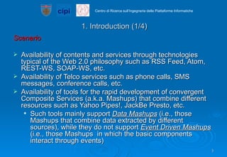
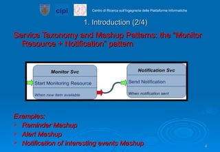
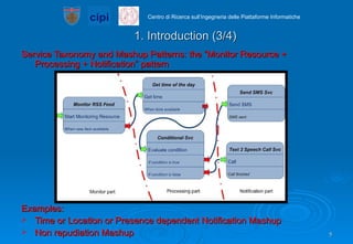
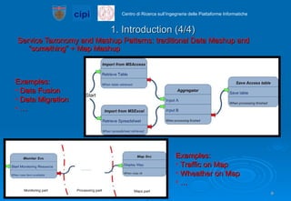
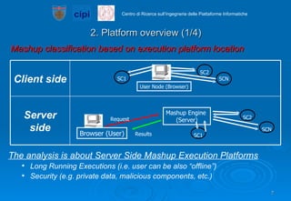

The document proposes an execution platform for event-driven mashups that: 1) Allows for the creation and deployment of event-driven mashups that combine various web services and resources. 2) Uses a sessionless orchestration model and asynchronous web service calls to provide automatic scalability and fault tolerance. 3) Was tested and shown to reduce latency when replicated across multiple nodes, demonstrating its ability to horizontally scale under load.