
![CHAPTER 1: Magnetic Field
• Magnetic field:
• Space around a magnet or current carrying conductor. [as the site of magnetic
field].
• Magnetic Induction: Symbol: B](https://image.slidesharecdn.com/unit2-210504114118/75/Magnetic-Field-and-Electromagnetic-Induction-2-2048.jpg)

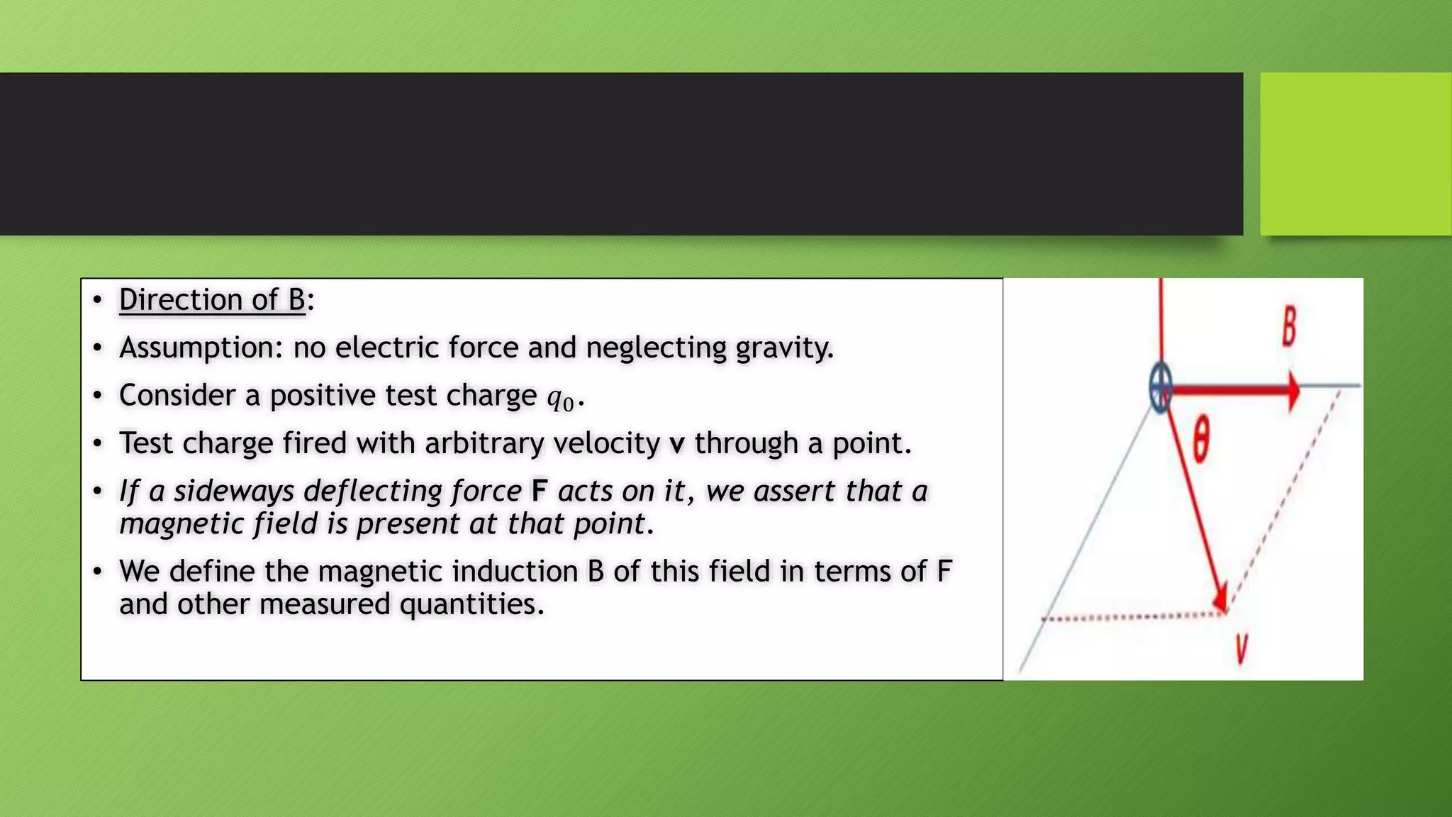
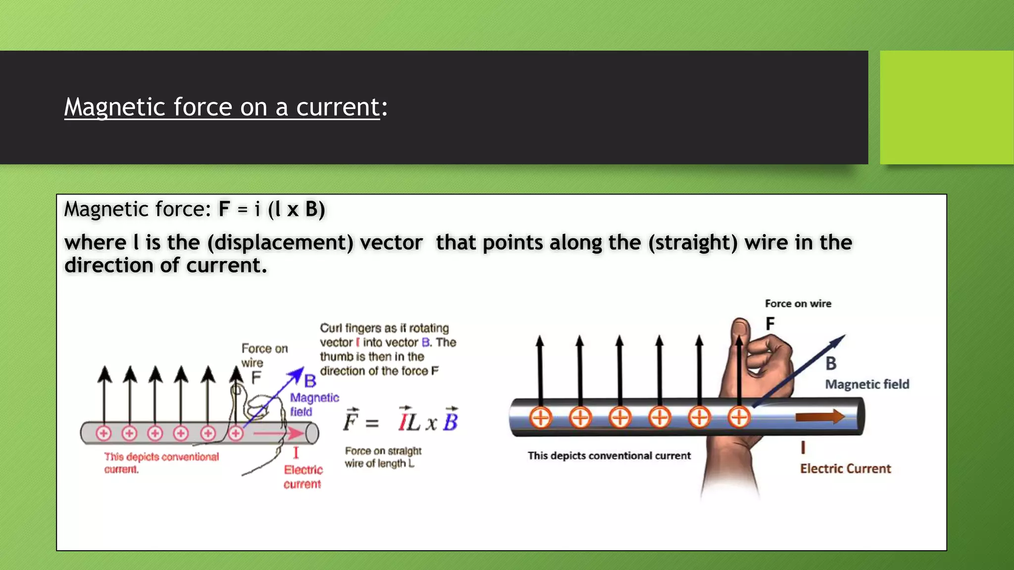
![• F = 𝑞0 v x B , F = 𝑞0𝑣𝐵𝑠𝑖𝑛𝜃
• Above equations show relation among the vectors.
• F is always at right angles to the plane formed by v and B and hence
always a sideways force.
• Consistency of the above equation: Special Case:
A. Case I: Magnetic force vanishes as v → 0.
B. Case II: Magnetic force vanishes if v is either parallel or antiparallel
to the direction of B [𝜃 = 0 or 𝜃 = 180]
C. Case III: If v is at right angles to B [𝜃 = 90] the deflecting force has a
maximum value F = 𝑞0𝑣𝐵](https://image.slidesharecdn.com/unit2-210504114118/75/Magnetic-Field-and-Electromagnetic-Induction-8-2048.jpg)


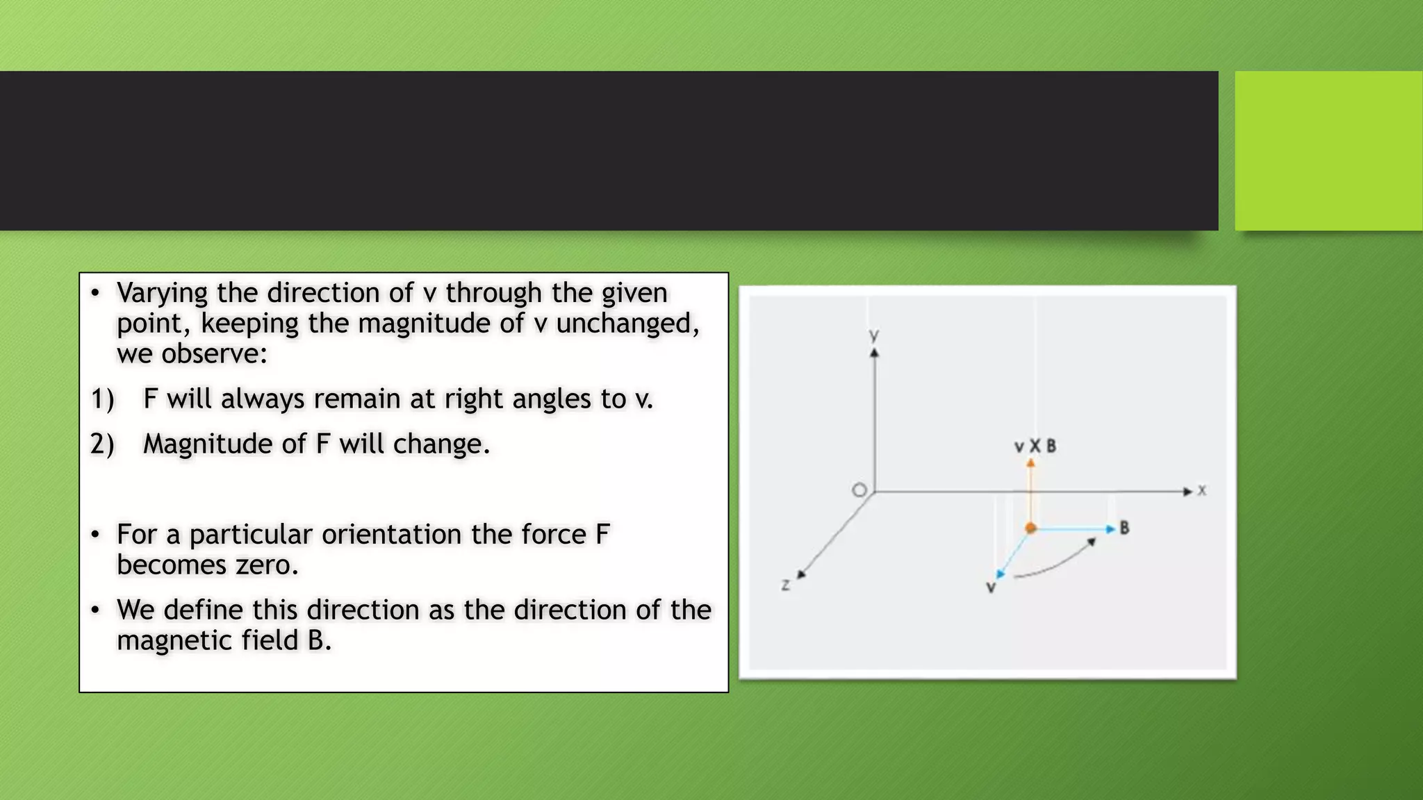
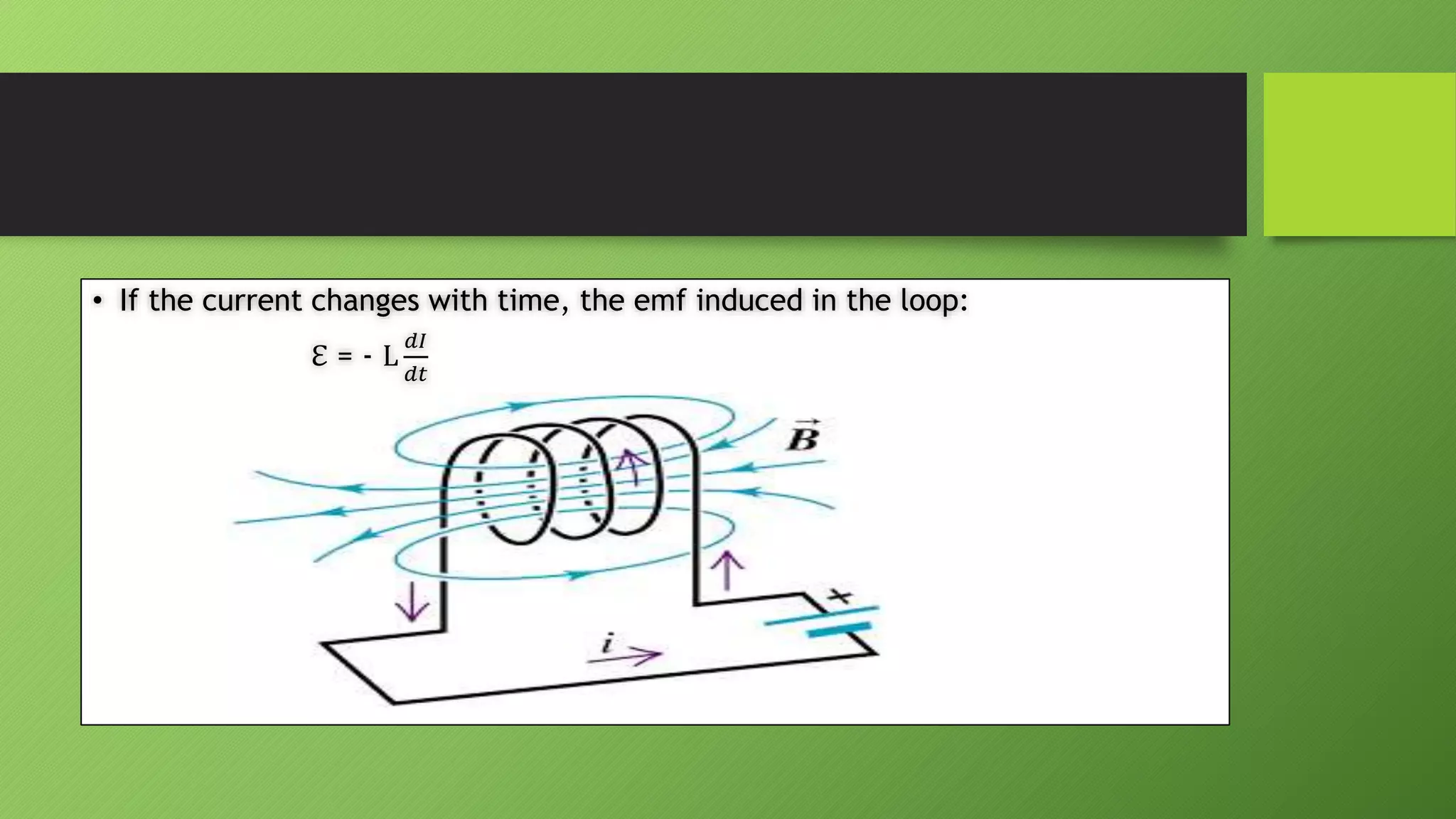
![• Faraday’s law of induction says that the induced emf ℇ in a circuit is equal to
the negative rate at which the flux through the circuit is changing given by:
ℇ = -
𝑑𝜑𝐵
𝑑𝑡
------[Faraday’s law of induction] -----(1)](https://image.slidesharecdn.com/unit2-210504114118/75/Magnetic-Field-and-Electromagnetic-Induction-24-2048.jpg)
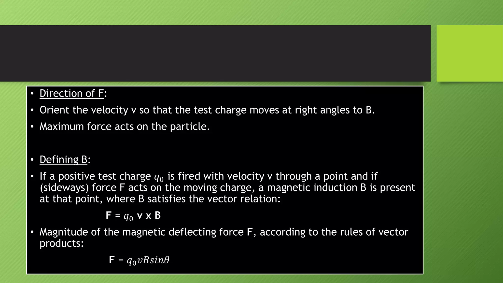
![• Equation [1] applied to a coil to N turns, an emf appears in every turn.
• Emfs needs to be added.
• If the coil is tightly wound that each turn can be occupies the same region of space, the flux
through each turn will be the same.
• The induced emf is given by:
ℇ = - N
𝑑𝜑𝐵
𝑑𝑡
= −
𝑑𝑁𝜑𝐵
𝑑𝑡
where 𝑁𝜑𝐵 is called the flux – linkages in the device.](https://image.slidesharecdn.com/unit2-210504114118/75/Magnetic-Field-and-Electromagnetic-Induction-25-2048.jpg)

![• A changing magnetic field induces an electric field.
ℇ = 𝐸. 𝑑𝑙 = -
𝑑𝜑𝐵
𝑑𝑡
• E is related to the change in B by equation:
𝐸. 𝑑𝑙 = -
𝜕𝐵
𝜕𝑡
. 𝑑𝑎 ---- [Faraday’s law in integral form]
• We can convert it to differential form by applying Stokes’ theorem:
∇ 𝑋 𝐸 = -
𝜕𝐵
𝜕𝑡](https://image.slidesharecdn.com/unit2-210504114118/75/Magnetic-Field-and-Electromagnetic-Induction-27-2048.jpg)
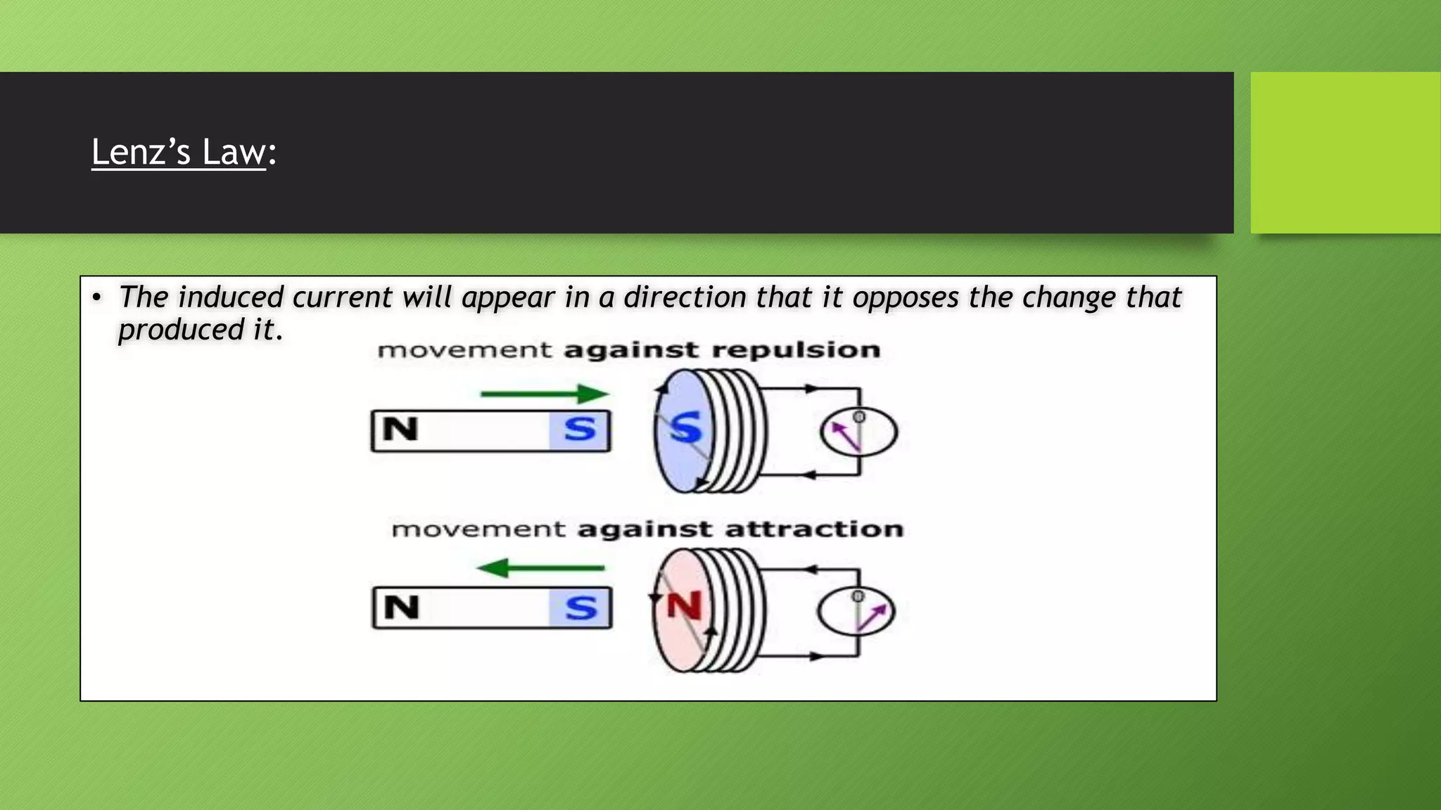


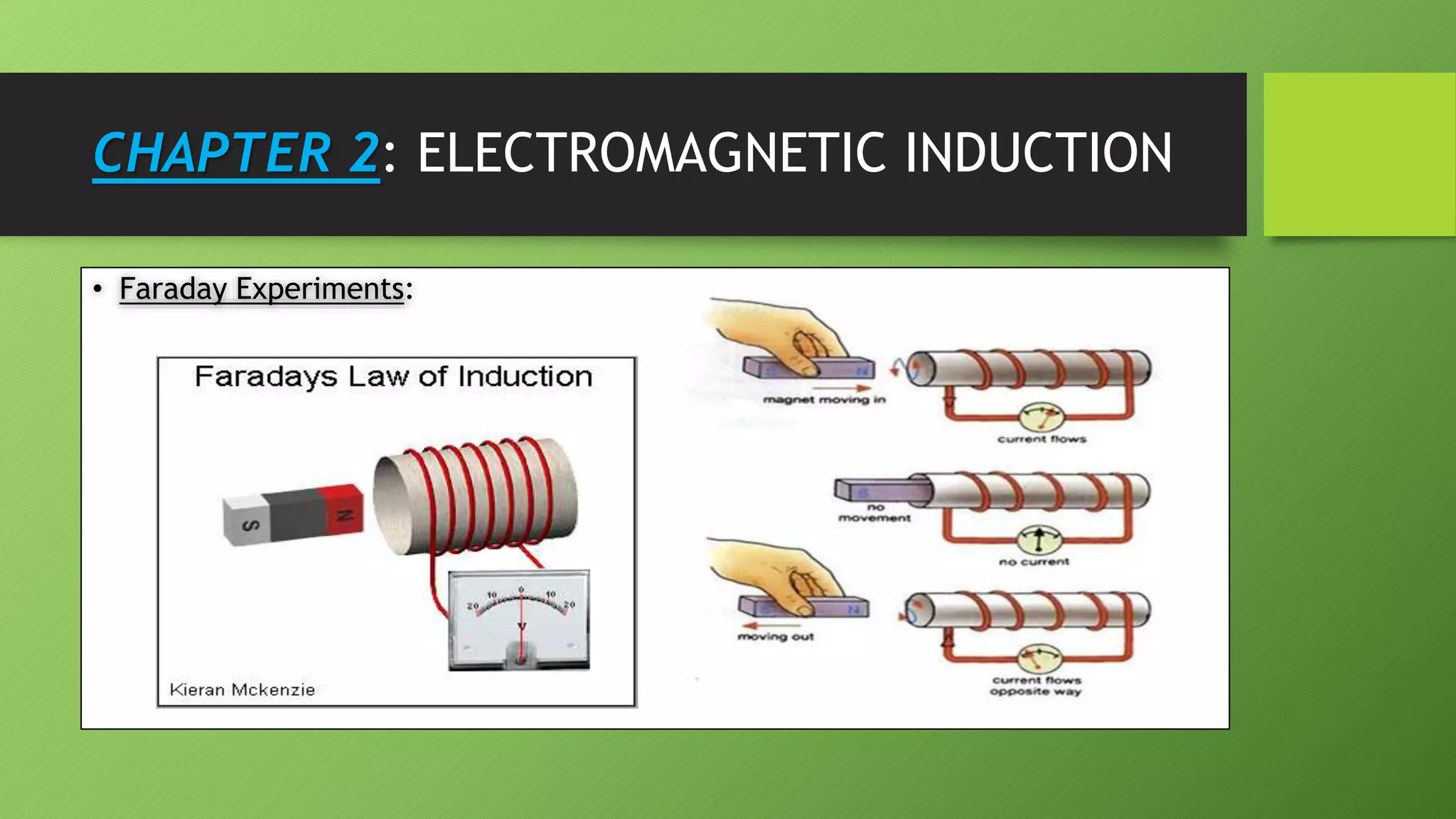
1) A magnetic field is defined as the space around a magnet or current-carrying conductor. Magnetic field lines indicate the direction of the field. 2) Faraday's experiments showed that a changing magnetic field induces an electromotive force (emf) in a nearby circuit. This is known as electromagnetic induction. 3) Lenz's law states that the direction of the induced current will always oppose the change that caused it. This ensures the conservation of energy.


